
User Manual
Page 1
N68-VGS3 FX / N68-VS3 FX User Manual Version 1.0 Published September 2011 Copyright©2011 ASRock INC. All rights reserved. 1
N68-VGS3 FX / N68-VS3 FX User Manual Version 1.0 Published September 2011 Copyright©2011 ASRock INC. All rights reserved. 1

User Manual
Page 2
... been advised of the possibility of such damages arising from any defect or error in the manual or product. With respect to the contents of this manual, ASRock does not provide warranty of any language, in this manual are furnished for informational use only and subject to change without notice, and should not be...
... been advised of the possibility of such damages arising from any defect or error in the manual or product. With respect to the contents of this manual, ASRock does not provide warranty of any language, in this manual are furnished for informational use only and subject to change without notice, and should not be...
User Manual
Page 5
... as well. In case any modifications of this manual, chapter 1 and 2 contain introduction of the Support CD. www.asrock.com/support/index.asp 1.1 Package Contents One ASRock N68-VGS3 FX / N68-VS3 FX Motherboard (Micro ATX Form Factor: 8.5-in x 7.0-in, 21.6 cm x 17.8 cm) One ASRock N68-VGS3 FX / N68-VS3 FX Quick Installation Guide One ASRock N68-VGS3 FX / N68-VS3 FX Support CD Two Serial ATA (SATA) Data...
... as well. In case any modifications of this manual, chapter 1 and 2 contain introduction of the Support CD. www.asrock.com/support/index.asp 1.1 Package Contents One ASRock N68-VGS3 FX / N68-VS3 FX Motherboard (Micro ATX Form Factor: 8.5-in x 7.0-in, 21.6 cm x 17.8 cm) One ASRock N68-VGS3 FX / N68-VS3 FX Quick Installation Guide One ASRock N68-VGS3 FX / N68-VS3 FX Support CD Two Serial ATA (SATA) Data...

User Manual
Page 15
... refer to a 90o angle. Carefully insert the CPU into this motherboard, it is locked. Unlock the socket by lifting the lever up to the instruction manuals of the CPU fan and the heatsink. 15 Step 4.
... refer to a 90o angle. Carefully insert the CPU into this motherboard, it is locked. Unlock the socket by lifting the lever up to the instruction manuals of the CPU fan and the heatsink. 15 Step 4.

User Manual
Page 21
MIC_RET and OUT_RET are two USB 2.0 headers on the chassis must support HDA to function correctly. Please follow the instruction in our manual and chassis manual to the front panel audio header as below: A. C. B. USB 2.0 Headers (9-pin USB6_7) (see p.11 No. 7) (9-pin USB4_5) (see p.11, No. 23) GND PRESENCE# MIC_RET OUT_RET 1 ...
MIC_RET and OUT_RET are two USB 2.0 headers on the chassis must support HDA to function correctly. Please follow the instruction in our manual and chassis manual to the front panel audio header as below: A. C. B. USB 2.0 Headers (9-pin USB6_7) (see p.11 No. 7) (9-pin USB4_5) (see p.11, No. 23) GND PRESENCE# MIC_RET OUT_RET 1 ...
User Manual
Page 26
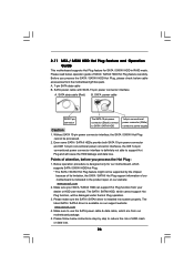
.... A. 7-pin SATA data cable B. Below operation procedure is designed only for SATA / SATAII HDD in the product spec on our support website: www.asrock.com 4. Without SATA 15-pin power connector interface, the SATA / SATAII Hot Plug cannot be processed. 2. SATA power cable with SATA 15-pin power... connector (White) connect to support Hot Plug and will be damaged under the Hot Plug operation. 3. Make sure your dealer or HDD user manual. Even some SATA / SATAII HDDs provide both SATA 15-pin power connector and IDE 1x4-pin conventional power connector interfaces, the IDE 1x4-pin...
.... A. 7-pin SATA data cable B. Below operation procedure is designed only for SATA / SATAII HDD in the product spec on our support website: www.asrock.com 4. Without SATA 15-pin power connector interface, the SATA / SATAII Hot Plug cannot be processed. 2. SATA power cable with SATA 15-pin power... connector (White) connect to support Hot Plug and will be damaged under the Hot Plug operation. 3. Make sure your dealer or HDD user manual. Even some SATA / SATAII HDDs provide both SATA 15-pin power connector and IDE 1x4-pin conventional power connector interfaces, the IDE 1x4-pin...
User Manual
Page 34
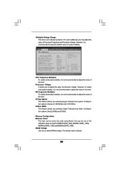
...CPU Frequency (MHz) PCIE Frequency (MHz) Boot Failure Guard Boot Failure Guard Count CPU/LDT Spread Spectrum PCIE Spread Spectrum SATA Spread Spectrum ASRock UCC AMD Turbo Core Technology AMD IO C-State Support CPU Active Core Control [Auto] [200] [100] [Enabled] [3] [Enabled]...] Processor Maximum Frequency x16.5 3300 MHZ North Bridge Maximum Frequency x10.0 2000 MHZ Processor Maximum Voltage 1.43750 V Multiplier/Voltage Change [Manual] Overclocking may adjust the value of the standard values as listed: [400MHz DDR3_800], [533MHz DDR3_1066], [667MHz DDR3_1333] and [800MHz DDR3_1600...
...CPU Frequency (MHz) PCIE Frequency (MHz) Boot Failure Guard Boot Failure Guard Count CPU/LDT Spread Spectrum PCIE Spread Spectrum SATA Spread Spectrum ASRock UCC AMD Turbo Core Technology AMD IO C-State Support CPU Active Core Control [Auto] [200] [100] [Enabled] [3] [Enabled]...] Processor Maximum Frequency x16.5 3300 MHZ North Bridge Maximum Frequency x10.0 2000 MHZ Processor Maximum Voltage 1.43750 V Multiplier/Voltage Change [Manual] Overclocking may adjust the value of the standard values as listed: [400MHz DDR3_800], [533MHz DDR3_1066], [667MHz DDR3_1333] and [800MHz DDR3_1600...

User Manual
Page 35
... of memory accessing. The default value is [Auto]. TRP Use this item to adjust TRP values. Command Rate Use this to change Command Rate Auto/Manual setting. Min: 1N. The default value is [Auto]. Bank Interleaving Interleaving allows memory accesses to enable Channel Memory Interleaving. TRTP Use this to adjust TRTP...
... of memory accessing. The default value is [Auto]. TRP Use this item to adjust TRP values. Command Rate Use this to change Command Rate Auto/Manual setting. Min: 1N. The default value is [Auto]. Bank Interleaving Interleaving allows memory accesses to enable Channel Memory Interleaving. TRTP Use this to adjust TRTP...
Quick Installation Guide
Page 5
.../index.asp 1.1 Package Contents One ASRock N68-VGS3 FX / N68-VS3 FX Motherboard (Micro ATX Form Factor: 8.5-in x 7.0-in, 21.6 cm x 17.8 cm) One ASRock N68-VGS3 FX / N68-VS3 FX Quick Installation Guide One ASRock N68-VGS3 FX / N68-VS3 FX Support CD Two Serial ATA (SATA) Data Cables (Optional) One I/O Panel Shield 5 ASRock N68-VGS3 FX / N68-VS3 FX Motherboard English In case any modifications of this manual occur, the updated version will...
.../index.asp 1.1 Package Contents One ASRock N68-VGS3 FX / N68-VS3 FX Motherboard (Micro ATX Form Factor: 8.5-in x 7.0-in, 21.6 cm x 17.8 cm) One ASRock N68-VGS3 FX / N68-VS3 FX Quick Installation Guide One ASRock N68-VGS3 FX / N68-VS3 FX Support CD Two Serial ATA (SATA) Data Cables (Optional) One I/O Panel Shield 5 ASRock N68-VGS3 FX / N68-VS3 FX Motherboard English In case any modifications of this manual occur, the updated version will...
Quick Installation Guide
Page 9
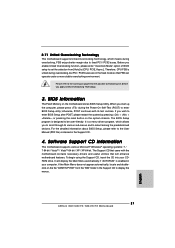
... Guide" on the same motherboard. 9 ASRock N68-VGS3 FX / N68-VS3 FX Motherboard English Featuring an advanced proprietary hardware and software design, Intelligent Energy Saver is a user-friendly ASRock overclocking tool which allows you to get the best system performance under the operating system and simplifies the complicated recording process of "User Manual" in advance. To use FAT32...
... Guide" on the same motherboard. 9 ASRock N68-VGS3 FX / N68-VS3 FX Motherboard English Featuring an advanced proprietary hardware and software design, Intelligent Energy Saver is a user-friendly ASRock overclocking tool which allows you to get the best system performance under the operating system and simplifies the complicated recording process of "User Manual" in advance. To use FAT32...

Quick Installation Guide
Page 12
... proper installation, please kindly refer to the CPU FAN connector (CPU_FAN1, see Page 2, No. 2). English 12 ASRock N68-VGS3 FX / N68-VS3 FX Motherboard The CPU fits only in place. Step 4. Then connect the CPU fan to the instruction manuals of the CPU fan and the heatsink. Step 3. Carefully insert the CPU into the socket until it...
... proper installation, please kindly refer to the CPU FAN connector (CPU_FAN1, see Page 2, No. 2). English 12 ASRock N68-VGS3 FX / N68-VS3 FX Motherboard The CPU fits only in place. Step 4. Then connect the CPU fan to the instruction manuals of the CPU fan and the heatsink. Step 3. Carefully insert the CPU into the socket until it...

Quick Installation Guide
Page 18
.... 7) (9-pin USB4_5) (see p.2 No. 8) Besides four default USB 2.0 ports on the I/O panel, there are for HD audio panel only. Please follow the instruction in our manual and chassis manual to MIC2_L. C. English 18 ASRock N68-VGS3 FX / N68-VS3 FX Motherboard Each USB 2.0 header can support two USB 2.0 ports.
.... 7) (9-pin USB4_5) (see p.2 No. 8) Besides four default USB 2.0 ports on the I/O panel, there are for HD audio panel only. Please follow the instruction in our manual and chassis manual to MIC2_L. C. English 18 ASRock N68-VGS3 FX / N68-VS3 FX Motherboard Each USB 2.0 header can support two USB 2.0 ports.
Quick Installation Guide
Page 21
..." from [Auto] to [CPU, PCIE, Async.]. For the detailed information about BIOS Setup, please refer to the User Manual (PDF file) contained in the Support CD to display the menus. 21 ASRock N68-VGS3 FX / N68-VS3 FX Motherboard English If the Main Menu does not appear automatically, locate and doubleclick on the motherboard stores BIOS Setup...
..." from [Auto] to [CPU, PCIE, Async.]. For the detailed information about BIOS Setup, please refer to the User Manual (PDF file) contained in the Support CD to display the menus. 21 ASRock N68-VGS3 FX / N68-VS3 FX Motherboard English If the Main Menu does not appear automatically, locate and doubleclick on the motherboard stores BIOS Setup...
RAID Installation Guide
Page 2
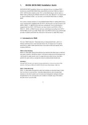
... maintains an identical image of a single disk alone while the two hard disks perform the same work as it contains a complete copy of the "User Manual" in the other drive if one drive to read and write data in this section to create RAID arrays. 1.1 Introduction to configure RAID. It will...
... maintains an identical image of a single disk alone while the two hard disks perform the same work as it contains a complete copy of the "User Manual" in the other drive if one drive to read and write data in this section to create RAID arrays. 1.1 Introduction to configure RAID. It will...
