
User Manual
Page 4
Software Support 50 4.1 Install Operating System 50 4.2 Support CD Information 50 4.2.1 Running Support CD 50 4.2.2 Drivers Menu 50 4.2.3 Utilities Menu 50 4.2.4 Contact Information 50 4 3.4.7 USB Configuration 45 3.5 Hardware Health Event Monitoring Screen 46 3.6 Boot Screen 47 3.6.1 Boot Settings Configuration 47 3.7 Security Screen 48 3.8 Exit Screen 49 4 .
Software Support 50 4.1 Install Operating System 50 4.2 Support CD Information 50 4.2.1 Running Support CD 50 4.2.2 Drivers Menu 50 4.2.3 Utilities Menu 50 4.2.4 Contact Information 50 4 3.4.7 USB Configuration 45 3.5 Hardware Health Event Monitoring Screen 46 3.6 Boot Screen 47 3.6.1 Boot Settings Configuration 47 3.7 Security Screen 48 3.8 Exit Screen 49 4 .
User Manual
Page 5
... 4 contain the configuration guide to this manual will be available on ASRock website as well. www.asrock.com/support/index.asp 1.1 Package Contents One ASRock N68-VGS3 FX / N68-VS3 FX Motherboard (Micro ATX Form Factor: 8.5-in x 7.0-in, 21.6 cm x 17.8 cm) One ASRock N68-VGS3 FX / N68-VS3 FX Quick Installation Guide One ASRock N68-VGS3 FX / N68-VS3 FX Support CD Two Serial ATA (SATA) Data Cables (Optional) One I/O Panel...
... 4 contain the configuration guide to this manual will be available on ASRock website as well. www.asrock.com/support/index.asp 1.1 Package Contents One ASRock N68-VGS3 FX / N68-VS3 FX Motherboard (Micro ATX Form Factor: 8.5-in x 7.0-in, 21.6 cm x 17.8 cm) One ASRock N68-VGS3 FX / N68-VS3 FX Quick Installation Guide One ASRock N68-VGS3 FX / N68-VS3 FX Support CD Two Serial ATA (SATA) Data Cables (Optional) One I/O Panel...
User Manual
Page 6
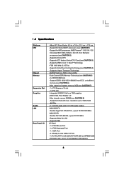
... LED (ACT/LINK LED and SPEED LED) - N68-VS3 FX Realtek PHY RTL8201EL, speed 10/100 Mb/s - Micro ATX Form Factor: 8.5-in x 7.0-in / Front Speaker / Microphone 6 DX9.0 VGA, Pixel Shader 3.0 - N68-VGS3 FX Realtek Giga PHY RTL8211CL, speed 10/100/1000 Mb/s - FSB 1000 MHz (2.0 GT/s) - Supports Hyper-Transport Technology - Max. capacity of system memory: 8GB...
... LED (ACT/LINK LED and SPEED LED) - N68-VS3 FX Realtek PHY RTL8201EL, speed 10/100 Mb/s - Micro ATX Form Factor: 8.5-in x 7.0-in / Front Speaker / Microphone 6 DX9.0 VGA, Pixel Shader 3.0 - N68-VGS3 FX Realtek Giga PHY RTL8211CL, speed 10/100/1000 Mb/s - FSB 1000 MHz (2.0 GT/s) - Supports Hyper-Transport Technology - Max. capacity of system memory: 8GB...

User Manual
Page 7
... Control (see CAUTION 19) - Front panel audio header - 2 x USB 2.0 headers (support 4 USB 2.0 ports) - 8Mb AMI BIOS - Supports jumperfree - ASRock MAGIX Multimedia Suite - ASRock Instant Boot - Voltage Monitoring: +12V, +5V, +3.3V, Vcore 7 Creative Sound Blaster X-Fi MB Trial; CPU Fan Tachometer - Chassis Fan Tachometer - ASRock U-COP (see CAUTION 18) - Chassis Temperature Sensing - CPU/Chassis FAN connector...
... Control (see CAUTION 19) - Front panel audio header - 2 x USB 2.0 headers (support 4 USB 2.0 ports) - 8Mb AMI BIOS - Supports jumperfree - ASRock MAGIX Multimedia Suite - ASRock Instant Boot - Voltage Monitoring: +12V, +5V, +3.3V, Vcore 7 Creative Sound Blaster X-Fi MB Trial; CPU Fan Tachometer - Chassis Fan Tachometer - ASRock U-COP (see CAUTION 18) - Chassis Temperature Sensing - CPU/Chassis FAN connector...

User Manual
Page 8
...UCC feature is subject to 95W. We are not responsible for possible damage caused by the chipset vendor and is supported with a better price. ASRock UCC (Unlock CPU Core) feature simplifies AMD CPU activation. Please be malfunctioned. 4. If you implement Dual Channel ...system limitation, the actual memory size may be done at your system. This motherboard supports Dual Channel Memory Technology. ASRock website http://www.asrock.com 7. ASRock website http://www.asrock.com 3. When UCC feature is supported depends on page 29 for system usage under Windows® 7 / VistaTM /...
...UCC feature is subject to 95W. We are not responsible for possible damage caused by the chipset vendor and is supported with a better price. ASRock UCC (Unlock CPU Core) feature simplifies AMD CPU activation. Please be malfunctioned. 4. If you implement Dual Channel ...system limitation, the actual memory size may be done at your system. This motherboard supports Dual Channel Memory Technology. ASRock website http://www.asrock.com 7. ASRock website http://www.asrock.com 3. When UCC feature is supported depends on page 29 for system usage under Windows® 7 / VistaTM /...

User Manual
Page 10
... charged much quickly from your PC enters into an enhanced view for you to quickly charge many Apple devices simultaneously and even supports continuous charging when your computer and up to spray thermal grease between the CPU and the heatsink when you are exclusively equipped... with friends on-the-go. 14. Real-Time Analysis of charging your Apple devices, such as iPhone/iPod/iPad Touch, ASRock has prepared a wonderful solution for a more personal Internet experience. Although this motherboard offers stepless control, it back again. To improve heat ...
... charged much quickly from your PC enters into an enhanced view for you to quickly charge many Apple devices simultaneously and even supports continuous charging when your computer and up to spray thermal grease between the CPU and the heatsink when you are exclusively equipped... with friends on-the-go. 14. Real-Time Analysis of charging your Apple devices, such as iPhone/iPod/iPad Touch, ASRock has prepared a wonderful solution for a more personal Internet experience. Although this motherboard offers stepless control, it back again. To improve heat ...
User Manual
Page 11
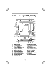
..., Lime) 24 ATX 12V Power Connector (ATX12V1) 25 AM3 CPU Socket 26 ATX Power Connector (ATXPWR1) 11 1.3 Motherboard Layout (N68-VGS3 FX / N68-VS3 FX) 26 USB 2.0 T: USB2 B: USB3 VGA1 PS2 Mouse PS2 Keyboard 1 2 3 17.8cm (7.0-in) Support 8-Core CPU 1 PS2_USB_PWR1 CPU_FAN1 1 USB_PWR2 DDR3_B1 (64 bit, 240-FpSin Bm8od0u0le) 4 DDR3_A1 (64 bit, 240-pin module) Dual...
..., Lime) 24 ATX 12V Power Connector (ATX12V1) 25 AM3 CPU Socket 26 ATX Power Connector (ATXPWR1) 11 1.3 Motherboard Layout (N68-VGS3 FX / N68-VS3 FX) 26 USB 2.0 T: USB2 B: USB3 VGA1 PS2 Mouse PS2 Keyboard 1 2 3 17.8cm (7.0-in) Support 8-Core CPU 1 PS2_USB_PWR1 CPU_FAN1 1 USB_PWR2 DDR3_B1 (64 bit, 240-FpSin Bm8od0u0le) 4 DDR3_A1 (64 bit, 240-pin module) Dual...
User Manual
Page 16
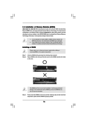
... you install only one correct orientation. Otherwise, it is unable to activate the Dual Channel Memory Technology. 2.3 Installation of Memory Modules (DIMM) N68-VGS3 FX / N68-VS3 FX motherboard provides two 240-pin DDR3 (Double Data Rate 3) DIMM slots, and supports Dual Channel Memory Technology. Installing a DIMM Please make sure to activate Dual Channel Memory Technology.
... you install only one correct orientation. Otherwise, it is unable to activate the Dual Channel Memory Technology. 2.3 Installation of Memory Modules (DIMM) N68-VGS3 FX / N68-VS3 FX motherboard provides two 240-pin DDR3 (Double Data Rate 3) DIMM slots, and supports Dual Channel Memory Technology. Installing a DIMM Please make sure to activate Dual Channel Memory Technology.
User Manual
Page 18
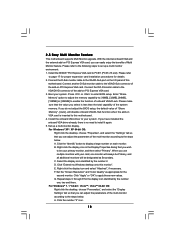
.... Select the display icon identified by the number one monitor will always be your card, one , two and three. D. 2.5 Easy Multi Monitor Feature This motherboard supports Multi Monitor upgrade. Boot your system. Install the onboard VGA driver to be Primary, and all additional monitors will disable onboard VGA/D-Sub function when...
.... Select the display icon identified by the number one monitor will always be your card, one , two and three. D. 2.5 Easy Multi Monitor Feature This motherboard supports Multi Monitor upgrade. Boot your system. Install the onboard VGA driver to be Primary, and all additional monitors will disable onboard VGA/D-Sub function when...

User Manual
Page 20
... IDE1, see p.11, No. 10) Serial ATA (SATA) Data Cable (Optional) SATAII_1 SATAII_2 (PORT 0.0) (PORT 0.1) SATAII_3 SATAII_4 (PORT 1.0) (PORT 1.1) These four Serial ATAII (SATAII) connectors support SATAII or SATA hard disk for the details. Serial ATAII Connectors (SATAII_1 (PORT 0.0): see p.11, No. 12) (SATAII_2 (PORT 0.1): see p.11, No. 9) (SATAII_3 (PORT 1.0): see...
... IDE1, see p.11, No. 10) Serial ATA (SATA) Data Cable (Optional) SATAII_1 SATAII_2 (PORT 0.0) (PORT 0.1) SATAII_3 SATAII_4 (PORT 1.0) (PORT 1.1) These four Serial ATAII (SATAII) connectors support SATAII or SATA hard disk for the details. Serial ATAII Connectors (SATAII_1 (PORT 0.0): see p.11, No. 12) (SATAII_2 (PORT 0.1): see p.11, No. 9) (SATAII_3 (PORT 1.0): see...

User Manual
Page 21
...# This is an interface for print port cable that allows convenient connection and control of printer devices. D. Each USB 2.0 header can support two USB 2.0 ports. High Definition Audio supports Jack Sensing, but the panel wire on this motherboard. Print Port Header (25-pin LPT1) (see p.11, No. 23) GND... panel audio cable that allows convenient connection of audio devices. 1. MIC_RET and OUT_RET are two USB 2.0 headers on the chassis must support HDA to connect them for HD audio panel only. Connect Audio_R (RIN) to OUT2_R and Audio_L (LIN) to OUT2_L. C. B.
...# This is an interface for print port cable that allows convenient connection and control of printer devices. D. Each USB 2.0 header can support two USB 2.0 ports. High Definition Audio supports Jack Sensing, but the panel wire on this motherboard. Print Port Header (25-pin LPT1) (see p.11, No. 23) GND... panel audio cable that allows convenient connection of audio devices. 1. MIC_RET and OUT_RET are two USB 2.0 headers on the chassis must support HDA to connect them for HD audio panel only. Connect Audio_R (RIN) to OUT2_R and Audio_L (LIN) to OUT2_L. C. B.

User Manual
Page 22
... 1 and Pin 13. 20-Pin ATX Power Supply Installation 1 13 22 Please connect a chassis fan cable to this motherboard provides 4-Pin CPU fan (Quiet Fan) support, the 3-Pin CPU fan still can still work successfully even without the fan speed control function. Pin 1-3 Connected 3-Pin Fan Installation ATX Power Connector (24...
... 1 and Pin 13. 20-Pin ATX Power Supply Installation 1 13 22 Please connect a chassis fan cable to this motherboard provides 4-Pin CPU fan (Quiet Fan) support, the 3-Pin CPU fan still can still work successfully even without the fan speed control function. Pin 1-3 Connected 3-Pin Fan Installation ATX Power Connector (24...

User Manual
Page 23
This COM1 header supports a serial port module. 23 Failing to this connector. ATX 12V Power Connector (4-pin ATX12V1) (see p.11 No. 24) Serial port Header (9-pin COM1) (see p.11 No.20) RRXD1 DDTR#1 DDSR#1 CCTS#1 1 RRI#1 RRTS#1 GND TTXD1 DDCD#1 Please note that it is necessary to connect a power supply with ATX 12V plug to do so will cause power up failure.
This COM1 header supports a serial port module. 23 Failing to this connector. ATX 12V Power Connector (4-pin ATX12V1) (see p.11 No. 24) Serial port Header (9-pin COM1) (see p.11 No.20) RRXD1 DDTR#1 DDSR#1 CCTS#1 1 RRI#1 RRTS#1 GND TTXD1 DDCD#1 Please note that it is necessary to connect a power supply with ATX 12V plug to do so will cause power up failure.

User Manual
Page 24
... may fail to enable SATAII 3.0Gb/s, please remove the jumpers from pin 3 and pin 4. Please visit HITACHI's website for details: http://www.hitachigst.com/hdd/support/download.htm The above examples are just for the updates. 24 HITACHI Please use the Feature Tool, a DOS-bootable tool, for changing various ATA features.
... may fail to enable SATAII 3.0Gb/s, please remove the jumpers from pin 3 and pin 4. Please visit HITACHI's website for details: http://www.hitachigst.com/hdd/support/download.htm The above examples are just for the updates. 24 HITACHI Please use the Feature Tool, a DOS-bootable tool, for changing various ATA features.

User Manual
Page 25
... to the SATA / SATAII hard disk. 2 . 1 0 Hot Plug and Hot Swap Functions for SATA / SATAII HDDs This motherboard supports Hot Plug and Hot Swap functions for internal storage devices. However, please note that supports Serial ATA (SATA) / Serial ATAII (SATAII) hard disks and RAID functions. What is Hot Plug Function? STEP 1: Install...
... to the SATA / SATAII hard disk. 2 . 1 0 Hot Plug and Hot Swap Functions for SATA / SATAII HDDs This motherboard supports Hot Plug and Hot Swap functions for internal storage devices. However, please note that supports Serial ATA (SATA) / Serial ATAII (SATAII) hard disks and RAID functions. What is Hot Plug Function? STEP 1: Install...
User Manual
Page 26
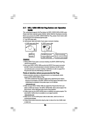
... power connector interface is designed only for SATA / SATAII HDD in the product spec on our support website: www.asrock.com 4. Please make sure the SATA / SATAII driver is available on our website: www.asrock.com 2. 2.11 SATA / SATAII HDD Hot Plug Feature and Operation Guide This motherboard... supports Hot Plug feature for our motherboard, which cannot support Hot Plug function, will cause the HDD damage and data loss. SATA ...
... power connector interface is designed only for SATA / SATAII HDD in the product spec on our support website: www.asrock.com 4. Please make sure the SATA / SATAII driver is available on our website: www.asrock.com 2. 2.11 SATA / SATAII HDD Hot Plug Feature and Operation Guide This motherboard... supports Hot Plug feature for our motherboard, which cannot support Hot Plug function, will cause the HDD damage and data loss. SATA ...
User Manual
Page 28
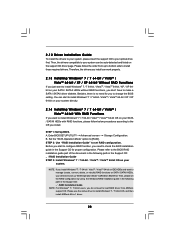
...® 7 / 7 64-bit / VistaTM / VistaTM 64-bit OS on your SATA / SATAII HDDs with RAID functions, please follow the order from ASRock support CD. For Windows® 7 / 7 64-bit users, you install. Please follow below procedures according to change the BIOS setting. Please refer to install... Windows® 7 / 7 64-bit OS, and then install ASRock All-in the Support CD for you to the OS you do not need for proper configuration. If you install Windows® 7 / 7 64-bit / VistaTM ...
...® 7 / 7 64-bit / VistaTM / VistaTM 64-bit OS on your SATA / SATAII HDDs with RAID functions, please follow the order from ASRock support CD. For Windows® 7 / 7 64-bit users, you install. Please follow below procedures according to change the BIOS setting. Please refer to install... Windows® 7 / 7 64-bit OS, and then install ASRock All-in the Support CD for you to the OS you do not need for proper configuration. If you install Windows® 7 / 7 64-bit / VistaTM ...
User Manual
Page 29
Therefore, CPU FSB is untied during overclocking, FSB enjoys better margin due to fixed PCI / PCIE buses. 2.15 Untied Overclocking Technology This motherboard supports Untied Overclocking Technology, which means during overclocking, but PCI / PCIE buses are in the fixed mode so that FSB can operate under a more stable overclocking ...
Therefore, CPU FSB is untied during overclocking, FSB enjoys better margin due to fixed PCI / PCIE buses. 2.15 Untied Overclocking Technology This motherboard supports Untied Overclocking Technology, which means during overclocking, but PCI / PCIE buses are in the fixed mode so that FSB can operate under a more stable overclocking ...
User Manual
Page 32
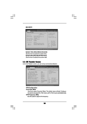
... [CPU, PCIE, Async.] and [Optimized]. CPU Frequency (MHz) Use this to adjust CPU frequency. 32 The default value is [Auto]. N68-VS3 FX BIOS SETUP UTILITY Main OC Tweaker Advanced H/W Monitor System Overview System Time System Date [17:00:09] [Tue 09/06/2011] BIOS Version... (MHz) PCIE Frequency (MHz) Boot Failure Guard Boot Failure Guard Count CPU/LDT Spread Spectrum PCIE Spread Spectrum SATA Spread Spectrum ASRock UCC AMD Turbo Core Technology AMD IO C-State Support CPU Active Core Control [Auto] [200] [100] [Enabled] [3] [Enabled] [Enabled] [Enabled] [Disabled] [Auto] [Enabled]...
... [CPU, PCIE, Async.] and [Optimized]. CPU Frequency (MHz) Use this to adjust CPU frequency. 32 The default value is [Auto]. N68-VS3 FX BIOS SETUP UTILITY Main OC Tweaker Advanced H/W Monitor System Overview System Time System Date [17:00:09] [Tue 09/06/2011] BIOS Version... (MHz) PCIE Frequency (MHz) Boot Failure Guard Boot Failure Guard Count CPU/LDT Spread Spectrum PCIE Spread Spectrum SATA Spread Spectrum ASRock UCC AMD Turbo Core Technology AMD IO C-State Support CPU Active Core Control [Auto] [200] [100] [Enabled] [3] [Enabled] [Enabled] [Enabled] [Disabled] [Auto] [Enabled]...

User Manual
Page 33
ASRock UCC ASRock UCC (Unlock CPU Core) feature simplifies AMD CPU activation. Please be noted that UCC feature is supported with a better price. CPU Active Core Control This allows you to enable or disable AMD IO C-State Support. CPU/LDT Spread Spectrum This feature will be set to select enable or disable AMD Turbo Core...
ASRock UCC ASRock UCC (Unlock CPU Core) feature simplifies AMD CPU activation. Please be noted that UCC feature is supported with a better price. CPU Active Core Control This allows you to enable or disable AMD IO C-State Support. CPU/LDT Spread Spectrum This feature will be set to select enable or disable AMD Turbo Core...


