
User Manual
Page 9
... microphone input, this motherboard supports 2-channel, 4-channel, 6-channel, and 8-channel modes. In Hardware Monitor, it shows the fan speed and temperature for proper connection. In OC DNA, you to use two of your system. Your friends then can support the same features as a pro le and share with your USB ash drive, oppy disk or hard 3. 4. 5. 6. 7. 8. 9. 9 With this tool and save your OC settings as HDMIport. This motherboard supports Dual Channel Memory Technology. Please check the...
... microphone input, this motherboard supports 2-channel, 4-channel, 6-channel, and 8-channel modes. In Hardware Monitor, it shows the fan speed and temperature for proper connection. In OC DNA, you to use two of your system. Your friends then can support the same features as a pro le and share with your USB ash drive, oppy disk or hard 3. 4. 5. 6. 7. 8. 9. 9 With this tool and save your OC settings as HDMIport. This motherboard supports Dual Channel Memory Technology. Please check the...
User Manual
Page 12
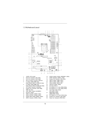
...) ATX Power Connector (ATXPWR1) Chassis Fan Connector (CHA_FAN2) 32Mb SPI Flash Clear CMOS Jumper (CLRCMOS1) Intel H61 Chipset SATA2 Connector (SATA2_0, Blue) SATA2 Connector (SATA2_2, Blue) System Panel Header (PANEL1, White) SATA2 Connector (SATA2_3, Blue) 16 17 18 19 20 21 22 23 24 25 26 27 28 29 30 Chassis Speaker Header (SPEAKER 1, White) SATA2 Connector (SATA2_1, Blue) Chassis Fan Connector (CHA_FAN1) USB 2.0 Header (USB8_9, Blue) USB 2.0 Header (USB6_7, Blue) Infrared Module Header (IR1) COM Port Header (COM1) PCI Slots (PCI1-2) PCI Express 2.0 x1 Slot...
...) ATX Power Connector (ATXPWR1) Chassis Fan Connector (CHA_FAN2) 32Mb SPI Flash Clear CMOS Jumper (CLRCMOS1) Intel H61 Chipset SATA2 Connector (SATA2_0, Blue) SATA2 Connector (SATA2_2, Blue) System Panel Header (PANEL1, White) SATA2 Connector (SATA2_3, Blue) 16 17 18 19 20 21 22 23 24 25 26 27 28 29 30 Chassis Speaker Header (SPEAKER 1, White) SATA2 Connector (SATA2_1, Blue) Chassis Fan Connector (CHA_FAN1) USB 2.0 Header (USB8_9, Blue) USB 2.0 Header (USB6_7, Blue) Infrared Module Header (IR1) COM Port Header (COM1) PCI Slots (PCI1-2) PCI Express 2.0 x1 Slot...
User Manual
Page 22
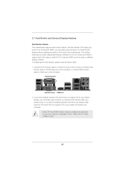
... installing any add-on the I/O panel. This motherboard also provides independent display controllers for DVI-D, D-Sub and HDMI to this motherboard. D-Sub, DVI-D and HDMI monitors cannot be enabled at the same time. To enable dual monitor feature, please follow the below steps: 1. You can drive same or different display contents. Connect DVI-D monitor cable to VGA/DVI-D port on the I/O panel, connect D-Sub monitor cable to VGA/D-Sub port on the I/O panel, or connect HDMI monitor cable to HDMI port on VGA card to support dual VGA...
... installing any add-on the I/O panel. This motherboard also provides independent display controllers for DVI-D, D-Sub and HDMI to this motherboard. D-Sub, DVI-D and HDMI monitors cannot be enabled at the same time. To enable dual monitor feature, please follow the below steps: 1. You can drive same or different display contents. Connect DVI-D monitor cable to VGA/DVI-D port on the I/O panel, connect D-Sub monitor cable to VGA/D-Sub port on the I/O panel, or connect HDMI monitor cable to HDMI port on VGA card to support dual VGA...
User Manual
Page 23
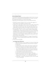
... "Apply" or "OK" to the corresponding connectors of "Onboard VGA Share Memory", [Auto], will be your system. With the internal VGA output support (DVI-D, D-Sub and HDMI) and external add-on the I /O panel, or connect HDMI monitor cable to HDMI port on PCI Express VGA cards, you do not adjust the UEFI setup, the default value of the add-on PCI Express VGA card on PCIE1 slot. 3. Then connect other monitor cables to apply these new values. Surround Display Feature This motherboard supports surround display upgrade.
... "Apply" or "OK" to the corresponding connectors of "Onboard VGA Share Memory", [Auto], will be your system. With the internal VGA output support (DVI-D, D-Sub and HDMI) and external add-on the I /O panel, or connect HDMI monitor cable to HDMI port on PCI Express VGA cards, you do not adjust the UEFI setup, the default value of the add-on PCI Express VGA card on PCIE1 slot. 3. Then connect other monitor cables to apply these new values. Surround Display Feature This motherboard supports surround display upgrade.
User Manual
Page 34
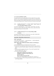
... key, and then a window for boot devices selection appears. The system will start to [AHCI]. Set the option "SATA Mode" to format the floppy diskette and copy SATA / SATAII drivers into the floppy drive. C. WARNING! Please follow below procedures according to the OS you install. 2.14.1 Installing Windows® XP / XP 64-bit Without RAID Functions If you want to generate Serial ATA driver diskette [YN]?", press . Using SATA / SATAII HDDs...
... key, and then a window for boot devices selection appears. The system will start to [AHCI]. Set the option "SATA Mode" to format the floppy diskette and copy SATA / SATAII drivers into the floppy drive. C. WARNING! Please follow below procedures according to the OS you install. 2.14.1 Installing Windows® XP / XP 64-bit Without RAID Functions If you want to generate Serial ATA driver diskette [YN]?", press . Using SATA / SATAII HDDs...
User Manual
Page 42
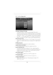
... of adjacent cache lines. The default value is [Auto]. 42 Active Processor Cores Use this to enable or disable CPU C3 (ACPI C2) report to [Enabled] if using Microsoft® Windows® XP, VistaTM, 7, or Linux kernel version 2.4.18 or higher. Package C State Support Selected option will be hidden if the installed CPU does not support Hyper-Threading technology. Set to OS. 3.4.1 CPU Configuration Intel Hyper Threading Technology To enable this feature, it requires...
... of adjacent cache lines. The default value is [Auto]. 42 Active Processor Cores Use this to enable or disable CPU C3 (ACPI C2) report to [Enabled] if using Microsoft® Windows® XP, VistaTM, 7, or Linux kernel version 2.4.18 or higher. Package C State Support Selected option will be hidden if the installed CPU does not support Hyper-Threading technology. Set to OS. 3.4.1 CPU Configuration Intel Hyper Threading Technology To enable this feature, it requires...

User Manual
Page 44
... the motherboard through ef cient memory utilization. The default value is [PCI Express]. DVMT Mode Select Use this to adjust DVMT mode. In DVMT mode, the graphics driver allocates memory as needed for Directed I/O). VT-d Use this option to enable or disable Intel® VT-d technology (Intel® Virtualization Technology for running graphics applications and is cooperatively using this feature is [64MB]. The default value is [Enabled]. Onboard VGA Share Memory This allows you to set onboard VGA share memory feature...
... the motherboard through ef cient memory utilization. The default value is [PCI Express]. DVMT Mode Select Use this to adjust DVMT mode. In DVMT mode, the graphics driver allocates memory as needed for Directed I/O). VT-d Use this option to enable or disable Intel® VT-d technology (Intel® Virtualization Technology for running graphics applications and is cooperatively using this feature is [64MB]. The default value is [Enabled]. Onboard VGA Share Memory This allows you to set onboard VGA share memory feature...
User Manual
Page 47
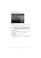
Con guration options: [IDE Mode], [AHCI Mode] and [Disabled]. Con guration options: [Disabled] and [Enabled]. 47 The default value is installed, please select [Enhanced]. SATA Controller 0 Please select [Compatible] when you install legacy OS. SATA Controller 1 Use this item to select SATA mode. Hard Disk S.M.A.R.T. 3.4.4 Storage Configuration SATA Mode Use this to enable or disable SATA Controller 1. Use this item to enable or disable the S.M.A.R.T. (Self-Monitoring, Analysis, and Reporting Technology) feature. AHCI (Advanced Host Controller Interface) supports NCQ and other ...
Con guration options: [IDE Mode], [AHCI Mode] and [Disabled]. Con guration options: [Disabled] and [Enabled]. 47 The default value is installed, please select [Enhanced]. SATA Controller 0 Please select [Compatible] when you install legacy OS. SATA Controller 1 Use this item to select SATA mode. Hard Disk S.M.A.R.T. 3.4.4 Storage Configuration SATA Mode Use this to enable or disable SATA Controller 1. Use this item to enable or disable the S.M.A.R.T. (Self-Monitoring, Analysis, and Reporting Technology) feature. AHCI (Advanced Host Controller Interface) supports NCQ and other ...

User Manual
Page 50
...: [Enabled] - Enables legacy support if USB devices are four con guration options: [Enabled], [Auto], [Disabled] and [UEFI Setup Only]. If you have USB compatibility issue, it is [Enabled]. Legacy USB Support Use this item to enable or disable the use under UEFI setup and Windows / Linux OS. 50 Please refer to below descriptions for USB devices. There are connected. [Disabled] - 3.4.7 USB Configuration USB 2.0 Controller Use this option to select legacy support for the details of USB 2.0 controller. The default value is recommended to select [Disabled] to enter OS. [UEFI...
...: [Enabled] - Enables legacy support if USB devices are four con guration options: [Enabled], [Auto], [Disabled] and [UEFI Setup Only]. If you have USB compatibility issue, it is [Enabled]. Legacy USB Support Use this item to enable or disable the use under UEFI setup and Windows / Linux OS. 50 Please refer to below descriptions for USB devices. There are connected. [Disabled] - 3.4.7 USB Configuration USB 2.0 Controller Use this option to select legacy support for the details of USB 2.0 controller. The default value is recommended to select [Disabled] to enter OS. [UEFI...

User Manual
Page 51
... On]. Chassis Fan 1 Setting This allows you to set the chassis fan 3 speed. The default value is [Enabled]. 51 Con guration options: [Full On] and [Automatic Mode]. Con guration options: [Full On] and [Automatic Mode]. Chassis Fan 3 Setting This allows you to set the chassis fan 1 speed. CPU Fan 1 & 2 Setting This allows you to monitor the status of the hardware on your system, including the parameters of the CPU temperature, motherboard temperature, CPU fan speed, chassis fan speed, and the critical voltage. Con guration options: [Full...
... On]. Chassis Fan 1 Setting This allows you to set the chassis fan 3 speed. The default value is [Enabled]. 51 Con guration options: [Full On] and [Automatic Mode]. Con guration options: [Full On] and [Automatic Mode]. Chassis Fan 3 Setting This allows you to set the chassis fan 1 speed. CPU Fan 1 & 2 Setting This allows you to monitor the status of the hardware on your system, including the parameters of the CPU temperature, motherboard temperature, CPU fan speed, chassis fan speed, and the critical voltage. Con guration options: [Full...
User Manual
Page 55
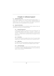
... reference only. Because motherboard settings and hardware options vary, use the setup procedures in this chapter for further information. 55 or you need to contact ASRock or want to display the menus. 4.2.2 Drivers Menu The Drivers Menu shows the available devices drivers if the system detects installed devices. Chapter 4: Software Support 4.1 Install Operating System This motherboard supports various Microsoft® Windows® operating systems: 7 / 7 64-bit / VistaTM / VistaTM 64-bit / XP / XP 64...
... reference only. Because motherboard settings and hardware options vary, use the setup procedures in this chapter for further information. 55 or you need to contact ASRock or want to display the menus. 4.2.2 Drivers Menu The Drivers Menu shows the available devices drivers if the system detects installed devices. Chapter 4: Software Support 4.1 Install Operating System This motherboard supports various Microsoft® Windows® operating systems: 7 / 7 64-bit / VistaTM / VistaTM 64-bit / XP / XP 64...

Quick Installation Guide
Page 2
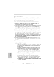
...-pin DDR3 DIMM Slots (Dual Channel: DDR3_A2, DDR3_B2, White) 7 ATX Power Connector (ATXPWR1) 8 Chassis Fan Connector (CHA_FAN2) 9 32Mb SPI Flash 10 Clear CMOS Jumper (CLRCMOS1) 11 Intel H61 Chipset 12 SATA2 Connector (SATA2_0, Blue) 13 SATA2 Connector (SATA2_2, Blue) 14 System Panel Header (PANEL1, White) 15 SATA2 Connector (SATA2_3, Blue) 16 Chassis Speaker Header (SPEAKER 1, White) 17 SATA2 Connector (SATA2_1, Blue) 18 Chassis Fan Connector (CHA_FAN1) 19 USB 2.0 Header (USB8_9, Blue) 20 USB 2.0 Header (USB6_7, Blue) 21 Infrared Module Header (IR1) 22 COM Port Header...
...-pin DDR3 DIMM Slots (Dual Channel: DDR3_A2, DDR3_B2, White) 7 ATX Power Connector (ATXPWR1) 8 Chassis Fan Connector (CHA_FAN2) 9 32Mb SPI Flash 10 Clear CMOS Jumper (CLRCMOS1) 11 Intel H61 Chipset 12 SATA2 Connector (SATA2_0, Blue) 13 SATA2 Connector (SATA2_2, Blue) 14 System Panel Header (PANEL1, White) 15 SATA2 Connector (SATA2_3, Blue) 16 Chassis Speaker Header (SPEAKER 1, White) 17 SATA2 Connector (SATA2_1, Blue) 18 Chassis Fan Connector (CHA_FAN1) 19 USB 2.0 Header (USB8_9, Blue) 20 USB 2.0 Header (USB6_7, Blue) 21 Infrared Module Header (IR1) 22 COM Port Header...
Quick Installation Guide
Page 3
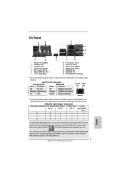
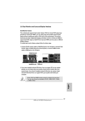
... front panel audio header. Please refer to the LAN port. Choose "2CH", "4CH", "6CH", or "8CH" and then you are two LED next to the table below for connection details in accordance with the type of speaker you need to connect a front panel audio cable to use front panel audio. 3 ASRock H61DE/SI Motherboard English TABLE for the LAN port LED indications. Please select "Mixer ToolBox" , click "Enable playback multi-streaming", and click "ok". LAN Port LED...
... front panel audio header. Please refer to the LAN port. Choose "2CH", "4CH", "6CH", or "8CH" and then you are two LED next to the table below for connection details in accordance with the type of speaker you need to connect a front panel audio cable to use front panel audio. 3 ASRock H61DE/SI Motherboard English TABLE for the LAN port LED indications. Please select "Mixer ToolBox" , click "Enable playback multi-streaming", and click "ok". LAN Port LED...
Quick Installation Guide
Page 4
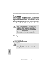
... latest VGA cards and CPU support lists on ASRock website without notice. www.asrock.com/support/index.asp 1.1 Package Contents ASRock H61DE/SI Motherboard (ATX Form Factor: 12.0-in x 8.6-in Storage Configuration to change without further notice. Introduction Thank you for specific information about the model you require technical support related to set the BIOS option in , 30.5 cm x 21.8 cm) ASRock H61DE/SI Quick Installation Guide ASRock H61DE/SI Support CD 2 x Serial ATA (SATA) Data Cables (Optional) 1 x I/O Panel Shield ASRock Reminds...
... latest VGA cards and CPU support lists on ASRock website without notice. www.asrock.com/support/index.asp 1.1 Package Contents ASRock H61DE/SI Motherboard (ATX Form Factor: 12.0-in x 8.6-in Storage Configuration to change without further notice. Introduction Thank you for specific information about the model you require technical support related to set the BIOS option in , 30.5 cm x 21.8 cm) ASRock H61DE/SI Quick Installation Guide ASRock H61DE/SI Support CD 2 x Serial ATA (SATA) Data Cables (Optional) 1 x I/O Panel Shield ASRock Reminds...
Quick Installation Guide
Page 8
... voltage regulator can press key during the POST or press key to BIOS setup menu to your OC settings as HDMIport. 6. This motherboard supports Dual Channel Memory Technology. You can save the new BIOS file to access ASRock Instant Flash. For Windows® OS with 64-bit CPU, there is supported under Windows® 7 64-bit / 7 / VistaTM 64-bit / VistaTM. 7. The maximum shared memory size is defined by the chipset vendor and is including Hardware Monitor, Fan Control, Overclocking...
... voltage regulator can press key during the POST or press key to BIOS setup menu to your OC settings as HDMIport. 6. This motherboard supports Dual Channel Memory Technology. You can save the new BIOS file to access ASRock Instant Flash. For Windows® OS with 64-bit CPU, there is supported under Windows® 7 64-bit / 7 / VistaTM 64-bit / VistaTM. 7. The maximum shared memory size is defined by the chipset vendor and is including Hardware Monitor, Fan Control, Overclocking...
Quick Installation Guide
Page 13
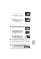
... onto the IHS. While pressing down lightly on load plate, engage the load lever. 2.2 Installation of CPU Fan and Heatsink For proper installation, please kindly refer to the instruction manuals of the heatsink for Socket LGA 1155/1156 CPU fan. 13 ASRock H61DE/SI Motherboard English Step 1. Align fasteners with thumb to the CPU fan connector on fastener caps with the motherboard throughholes. Step 5. Rotate the fastener clockwise, then press down the...
... onto the IHS. While pressing down lightly on load plate, engage the load lever. 2.2 Installation of CPU Fan and Heatsink For proper installation, please kindly refer to the instruction manuals of the heatsink for Socket LGA 1155/1156 CPU fan. 13 ASRock H61DE/SI Motherboard English Step 1. Align fasteners with thumb to the CPU fan connector on fastener caps with the motherboard throughholes. Step 5. Rotate the fastener clockwise, then press down the...
Quick Installation Guide
Page 17
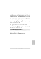
... provides independent display controllers for DVI-D, D-Sub and HDMI to HDMI port on the I/O panel, or connect HDMI monitor cable to support dual VGA output so that DVI-D, D-sub and HDMI can only choose the combination: DVI-D + HDMI, DVI-D + D-Sub, or HDMI + D-Sub. 17 ASRock H61DE/SI Motherboard English If you can easily enjoy the benefits of dual monitor function after your system already, you have installed onboard VGA driver from our support CD to...
... provides independent display controllers for DVI-D, D-Sub and HDMI to HDMI port on the I/O panel, or connect HDMI monitor cable to support dual VGA output so that DVI-D, D-sub and HDMI can only choose the combination: DVI-D + HDMI, DVI-D + D-Sub, or HDMI + D-Sub. 17 ASRock H61DE/SI Motherboard English If you can easily enjoy the benefits of dual monitor function after your system already, you have installed onboard VGA driver from our support CD to...
Quick Installation Guide
Page 18
... the second monitor. Boot your primary monitor, and then select "Primary". D. With the internal VGA output support (DVI-D, D-Sub and HDMI) and external add-on the I /O panel, connect D-Sub monitor cable to VGA/D-Sub port on PCI Express VGA cards, you have installed the drivers already, there is less than the total capability of "Onboard VGA Share Memory", [Auto], will be your system. A. Set the "Screen Resolution" and "Color Quality" as Secondary. Select the display icon...
... the second monitor. Boot your primary monitor, and then select "Primary". D. With the internal VGA output support (DVI-D, D-Sub and HDMI) and external add-on the I /O panel, connect D-Sub monitor cable to VGA/D-Sub port on PCI Express VGA cards, you have installed the drivers already, there is less than the total capability of "Onboard VGA Share Memory", [Auto], will be your system. A. Set the "Screen Resolution" and "Color Quality" as Secondary. Select the display icon...
Quick Installation Guide
Page 25
Therefore, the drivers you install can be auto-detected and listed on your system. 25 ASRock H61DE/SI Motherboard English B. STEP 2: Install Windows® XP / XP 64-bit OS on the support CD driver page. Using SATA / SATAII HDDs without NCQ function STEP 1: Set up to bottom side to your system can work properly. 2.9 Installing Windows® 7 / 7 64-bit / VistaTM / VistaTM 64-bit / XP / XP 64-bit Without RAID Functions If you want to install Windows®...
Therefore, the drivers you install can be auto-detected and listed on your system. 25 ASRock H61DE/SI Motherboard English B. STEP 2: Install Windows® XP / XP 64-bit OS on the support CD driver page. Using SATA / SATAII HDDs without NCQ function STEP 1: Set up to bottom side to your system can work properly. 2.9 Installing Windows® 7 / 7 64-bit / VistaTM / VistaTM 64-bit / XP / XP 64-bit Without RAID Functions If you want to install Windows®...
Quick Installation Guide
Page 27
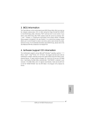
... Power-On-Self-Test (POST) to enter BIOS Setup utility; It is a menu-driven program, which allows you to enter BIOS Setup after POST, please restart the system by pressing + + , or pressing the reset button on the system chassis. For the detailed information about BIOS Setup, please refer to display the menus. 27 ASRock H61DE/SI Motherboard English Software Support CD information This motherboard supports various Microsoft® Windows® operating systems: 7 / 7 64-bit / VistaTM / VistaTM 64-bit...
... Power-On-Self-Test (POST) to enter BIOS Setup utility; It is a menu-driven program, which allows you to enter BIOS Setup after POST, please restart the system by pressing + + , or pressing the reset button on the system chassis. For the detailed information about BIOS Setup, please refer to display the menus. 27 ASRock H61DE/SI Motherboard English Software Support CD information This motherboard supports various Microsoft® Windows® operating systems: 7 / 7 64-bit / VistaTM / VistaTM 64-bit...


