User Manual
Page 3
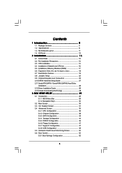
... Guide 27 2.11 Serial ATA (SATA) / Serial ATAII (SATAII) Hard Disks Installation 28 2.12 Driver Installation Guide 28 2.13 Untied Overclocking Technology 28 3 BIOS SETUP UTILITY 29 3.1 Introduction 29 3.1.1 BIOS Menu Bar 29 3.1.2 Navigation Keys 30 3.2 Main Screen 30 3.3 OC Tweaker Screen 31 3.4 Advanced Screen 35 3.4.1 CPU Configuration 36 3.4.2 Chipset Configuration 38...
... Guide 27 2.11 Serial ATA (SATA) / Serial ATAII (SATAII) Hard Disks Installation 28 2.12 Driver Installation Guide 28 2.13 Untied Overclocking Technology 28 3 BIOS SETUP UTILITY 29 3.1 Introduction 29 3.1.1 BIOS Menu Bar 29 3.1.2 Navigation Keys 30 3.2 Main Screen 30 3.3 OC Tweaker Screen 31 3.4 Advanced Screen 35 3.4.1 CPU Configuration 36 3.4.2 Chipset Configuration 38...
User Manual
Page 5
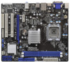
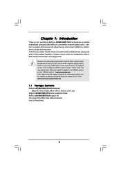
... of this motherboard, please visit our website for purchasing ASRock G41MH/USB3 R2.0 motherboard, a reliable motherboard produced under ASRock's consistently stringent quality control. ASRock website http://www.asrock.com If you for specific information about the model you are using. Chapter 3 and 4 contain the configuration guide to BIOS setup and information of the motherboard and step-by-step...
... of this motherboard, please visit our website for purchasing ASRock G41MH/USB3 R2.0 motherboard, a reliable motherboard produced under ASRock's consistently stringent quality control. ASRock website http://www.asrock.com If you for specific information about the model you are using. Chapter 3 and 4 contain the configuration guide to BIOS setup and information of the motherboard and step-by-step...
User Manual
Page 7
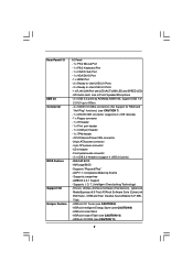
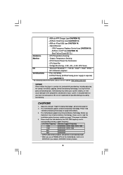
... jumperfree - Drivers, Utilities, AntiVirus Software (Trial Version), CyberLink MediaEspresso 6.5 Trial, ASRock Software Suite (CyberLink DVD Suite - Creative Sound Blaster X-Fi MB Trial) - AMI Legal BIOS - T. (Intelligent Overclocking Technology) - OEM and Trial; CPU/Chassis/Power FAN connector... connector - 4 pin 12V power connector - AMBIOS 2.3.1 Support - ASRock Intelligent Energy Saver (see CAUTION 10) - Front panel audio connector - 2 x USB 2.0 headers (support 4 USB 2.0 ports) - 8Mb AMI BIOS - ASRock OC DNA (see CAUTION 8) - CD in /Front Speaker/Microphone...
... jumperfree - Drivers, Utilities, AntiVirus Software (Trial Version), CyberLink MediaEspresso 6.5 Trial, ASRock Software Suite (CyberLink DVD Suite - Creative Sound Blaster X-Fi MB Trial) - AMI Legal BIOS - T. (Intelligent Overclocking Technology) - OEM and Trial; CPU/Chassis/Power FAN connector... connector - 4 pin 12V power connector - AMBIOS 2.3.1 Support - ASRock Intelligent Energy Saver (see CAUTION 10) - Front panel audio connector - 2 x USB 2.0 headers (support 4 USB 2.0 ports) - 8Mb AMI BIOS - ASRock OC DNA (see CAUTION 8) - CD in /Front Speaker/Microphone...
User Manual
Page 8
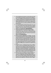
...This motherboard supports Untied Overclocking Technology. Before you use a FSB533-CPU on this motherboard, it will run at your own risk and expense. ASRock SmartView (see CAUTION 16) - Hybrid Booster: - CPU Temperature Sensing Monitor - ErP/EuP Ready (ErP/EuP ready power supply is a certain...800, DDR3 1066 800 DDR3 800 533 DDR3 800 * DDR3 1333 memory modules will operate in the BIOS, applying Untied Overclocking Technology, or using the thirdparty overclocking tools. ASRock APP Charger (see CAUTION 15) - Please read the installation guide of memory modules on page 28...
...This motherboard supports Untied Overclocking Technology. Before you use a FSB533-CPU on this motherboard, it will run at your own risk and expense. ASRock SmartView (see CAUTION 16) - Hybrid Booster: - CPU Temperature Sensing Monitor - ErP/EuP Ready (ErP/EuP ready power supply is a certain...800, DDR3 1066 800 DDR3 800 533 DDR3 800 * DDR3 1333 memory modules will operate in the BIOS, applying Untied Overclocking Technology, or using the thirdparty overclocking tools. ASRock APP Charger (see CAUTION 15) - Please read the installation guide of memory modules on page 28...
User Manual
Page 9
...there is subject to get the best system performance under Windows® environment. It is a user-friendly ASRock overclocking tool which allows you what it is a BIOS flash utility embedded in a few clicks without preparing an additional floppy diskette or other words, it makes ...under the operating system and simplifies the complicated recording process of ASRock OC Tuner. ASRock website: http://www.asrock.com 9. ASRock website: http://www.asrock.com 10. Just launch this utility, you - It helps you can save your BIOS only in Flash ROM. For Windows® OS with others...
...there is subject to get the best system performance under Windows® environment. It is a user-friendly ASRock overclocking tool which allows you what it is a BIOS flash utility embedded in a few clicks without preparing an additional floppy diskette or other words, it makes ...under the operating system and simplifies the complicated recording process of ASRock OC Tuner. ASRock website: http://www.asrock.com 9. ASRock website: http://www.asrock.com 10. Just launch this utility, you - It helps you can save your BIOS only in Flash ROM. For Windows® OS with others...
User Manual
Page 11
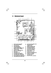
... Connector (FLOPPY1) 8 Chassis Fan Connector (CHA_FAN1) 24 Serial Port Connector (COM1) 9 IDE1 Connector (IDE1, Blue) 25 PCI Slots (PCI1- 2) 10 BIOS SPI Chip 26 PCI Express x16 Slot (PCIE2) 11 South Bridge Controller 27 Internal Audio Connector: CD1 (Black) 12 Clear CMOS Jumper (CLRCMOS1) 28 PCI...6 DDR3_B1 (64 bit, 240-pin module) DDR3_A1 (64 bit, 240-pin module) HDMI1 24.4cm (9.6 in) G41MH/USB3 29 LAN PHY USB 2.0 T: USB0 B: USB1 Top: RJ-45 USB 3.0 T: USB2 B: USB3 HD_AUDIO1 Intel G41 Chipset TPM1 1 7 CHA_FAN1 8 1 ErP/EuP Ready Gigabit LAN Top: LINE IN Center: FRONT ...
... Connector (FLOPPY1) 8 Chassis Fan Connector (CHA_FAN1) 24 Serial Port Connector (COM1) 9 IDE1 Connector (IDE1, Blue) 25 PCI Slots (PCI1- 2) 10 BIOS SPI Chip 26 PCI Express x16 Slot (PCIE2) 11 South Bridge Controller 27 Internal Audio Connector: CD1 (Black) 12 Clear CMOS Jumper (CLRCMOS1) 28 PCI...6 DDR3_B1 (64 bit, 240-pin module) DDR3_A1 (64 bit, 240-pin module) HDMI1 24.4cm (9.6 in) G41MH/USB3 29 LAN PHY USB 2.0 T: USB0 B: USB1 Top: RJ-45 USB 3.0 T: USB2 B: USB3 HD_AUDIO1 Intel G41 Chipset TPM1 1 7 CHA_FAN1 8 1 ErP/EuP Ready Gigabit LAN Top: LINE IN Center: FRONT ...
User Manual
Page 28
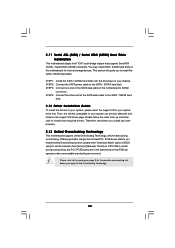
..., CPU FSB is untied during overclocking, FSB enjoys better margin due to [Manual]. STEP 1: Install the SATA / SATAII hard disks into the drive bays of BIOS setup to set the selection from up to bottom side to install the SATA / SATAII hard disks. You may install SATA / SATAII hard disks on...
..., CPU FSB is untied during overclocking, FSB enjoys better margin due to [Manual]. STEP 1: Install the SATA / SATAII hard disks into the drive bays of BIOS setup to set the selection from up to bottom side to install the SATA / SATAII hard disks. You may install SATA / SATAII hard disks on...
User Manual
Page 29
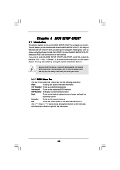
..., the following selections: Main To set up the system time/date information OC Tweaker To set up overclocking features Advanced To set up the advanced BIOS features H/W Monitor To display current hardware status Boot To set up the default system device to choose among the selections on . Chapter..., and then press to get into the sub screen. 29 If you start up the security features Exit To exit the current screen or the BIOS SETUP UTILITY Use < > key or < > key to locate and load the Operating System Security To set up the computer. The SPI Memory on the system...
..., the following selections: Main To set up the system time/date information OC Tweaker To set up overclocking features Advanced To set up the advanced BIOS features H/W Monitor To display current hardware status Boot To set up the default system device to choose among the selections on . Chapter..., and then press to get into the sub screen. 29 If you start up the security features Exit To exit the current screen or the BIOS SETUP UTILITY Use < > key or < > key to locate and load the Operating System Security To set up the computer. The SPI Memory on the system...
User Manual
Page 30
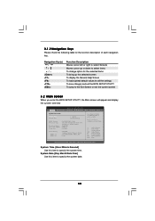
... UTILITY Main OC Tweaker Advanced H/W Monitor Boot Security Exit System Overview System Time System Date [14:00:09] [Fri 05/20/2011] BIOS Version : G41MH/USB3 P1.00 Processor Type : Intel (R) Pentium (R) Dual CPU E2220 @ 2.40GHz (64bit) Processor Speed : 2400MHz Microcode Update : 6FB/A3 Cache Size : 1024KB Total Memory DDR3_A1 DDR3_A2 : ...
... UTILITY Main OC Tweaker Advanced H/W Monitor Boot Security Exit System Overview System Time System Date [14:00:09] [Fri 05/20/2011] BIOS Version : G41MH/USB3 P1.00 Processor Type : Intel (R) Pentium (R) Dual CPU E2220 @ 2.40GHz (64bit) Processor Speed : 2400MHz Microcode Update : 6FB/A3 Cache Size : 1024KB Total Memory DDR3_A1 DDR3_A2 : ...
User Manual
Page 31
... depend on this motherboard. Load CPU EZ OC Setting You can set up overclocking features. You may cause damage to your own risk and expense. BIOS SETUP UTILITY Main OC Tweaker Advanced H/W Monitor Boot Security Exit OC Tweaker Settings Load CPU EZ OC Setting [Disabled] DRAM Frequency DRAM Command Rate DRAM...
... depend on this motherboard. Load CPU EZ OC Setting You can set up overclocking features. You may cause damage to your own risk and expense. BIOS SETUP UTILITY Main OC Tweaker Advanced H/W Monitor Boot Security Exit OC Tweaker Settings Load CPU EZ OC Setting [Disabled] DRAM Frequency DRAM Command Rate DRAM...
User Manual
Page 32
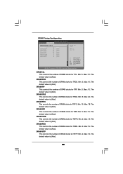
... is [Auto]. 32 Max: 78. DRAM tWR This controls the number of DRAM clocks for TRP. Min: 3. The default value is [Auto]. DRAM Timing Configuration BIOS SETUP UTILITY OC Tweaker DRAM Timing Control DRAM tCL 6 DRAM tRCD 6 DRAM tRP 6 DRAM tRAS 15 DRAM tRFC 44 DRAM tWR 6 DRAM tWTR 4 DRAM tRRD...
... is [Auto]. 32 Max: 78. DRAM tWR This controls the number of DRAM clocks for TRP. Min: 3. The default value is [Auto]. DRAM Timing Configuration BIOS SETUP UTILITY OC Tweaker DRAM Timing Control DRAM tCL 6 DRAM tRCD 6 DRAM tRP 6 DRAM tRAS 15 DRAM tRFC 44 DRAM tWR 6 DRAM tWTR 4 DRAM tRRD...
User Manual
Page 35
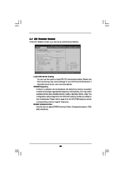
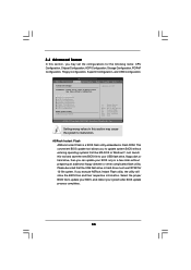
... complicated flash utility. CPU Configuration Chipset Configuration ACPI Configuration Storage Configuration PCIPnP Configuration Floppy Configuration SuperIO Configuration USB Configuration BIOS Update Utility ASRock Instant Flash Select Screen Select Item Enter Go to malfunction. Please be noted that the USB flash drive or...Load Defaults F10 Save and Exit ESC Exit v02.54 (C) Copyright 1985-2005, American Megatrends, Inc. ASRock Instant Flash ASRock Instant Flash is a BIOS flash utility embedded in below sections may set the configurations for CPU WARNING : Setting wrong values in Flash...
... complicated flash utility. CPU Configuration Chipset Configuration ACPI Configuration Storage Configuration PCIPnP Configuration Floppy Configuration SuperIO Configuration USB Configuration BIOS Update Utility ASRock Instant Flash Select Screen Select Item Enter Go to malfunction. Please be noted that the USB flash drive or...Load Defaults F10 Save and Exit ESC Exit v02.54 (C) Copyright 1985-2005, American Megatrends, Inc. ASRock Instant Flash ASRock Instant Flash is a BIOS flash utility embedded in below sections may set the configurations for CPU WARNING : Setting wrong values in Flash...
User Manual
Page 36
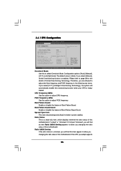
... this motherboard. Ratio CMOS Setting If the ratio status is heavy loaded. Please refer to select Overclock Mode. If you adopt supports 36 3.4.1 CPU Configuration BIOS SETUP UTILITY Advanced CPU Configuration Overclock Mode CPU Frequency (MHz) PCIE Frequency (MHz) Boot Failure Guard Boot Failure Guard Count Spread Spectrum [Auto] [200] [100...
... this motherboard. Ratio CMOS Setting If the ratio status is heavy loaded. Please refer to select Overclock Mode. If you adopt supports 36 3.4.1 CPU Configuration BIOS SETUP UTILITY Advanced CPU Configuration Overclock Mode CPU Frequency (MHz) PCIE Frequency (MHz) Boot Failure Guard Boot Failure Guard Count Spread Spectrum [Auto] [200] [100...
User Manual
Page 38
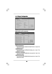
...ODT. Min: 1. DRAM CH0 G2 (Control1) This controls the number of DRAM CH0 G1 (Command). DRAM RCOMP and tRD Configuration BIOS SETUP UTILITY Advanced DRAM RCOMP STRENGTH Settings DRAM CH0 RCOMP STRENGTH Info : 54-0-11-6-6-6-6 DRAM CH0 RCOMP ODT DRAM CH0 G0 (Data)... G1 (Command) This controls the number of DRAM CH0 G2 (Control1). Max: 15. Max: 15. Max: 15. 3.4.2 Chipset Configuration BIOS SETUP UTILITY Advanced Chipset Settings DRAM RCOMP and tRD Configuration DRAM DLL SKEW Configuration Fixed Mode Operation [Enabled] Intelligent Energy Saver Primary Graphics Adapter Shared...
...ODT. Min: 1. DRAM CH0 G2 (Control1) This controls the number of DRAM CH0 G1 (Command). DRAM RCOMP and tRD Configuration BIOS SETUP UTILITY Advanced DRAM RCOMP STRENGTH Settings DRAM CH0 RCOMP STRENGTH Info : 54-0-11-6-6-6-6 DRAM CH0 RCOMP ODT DRAM CH0 G0 (Data)... G1 (Command) This controls the number of DRAM CH0 G2 (Control1). Max: 15. Max: 15. Max: 15. 3.4.2 Chipset Configuration BIOS SETUP UTILITY Advanced Chipset Settings DRAM RCOMP and tRD Configuration DRAM DLL SKEW Configuration Fixed Mode Operation [Enabled] Intelligent Energy Saver Primary Graphics Adapter Shared...
User Manual
Page 40
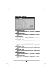
... is [Auto]. 40 DRAM CH0 CTRL2 SKEW This controls the number of DRAM CH0 CLKSET0 SKEW. The default value is [Auto]. DRAM DLL SKEW Configuration BIOS SETUP UTILITY Advanced DRAM DLL SKEW Settings DRAM CH0 CLKSET0 SKEW Info:0-0-0-0-0-0 DRAM CH0 CLKSET0 SKEW [Auto] DRAM CH0 CLKSET1 SKEW Info:0-0-0-0-0-0 DRAM CH0 CLKSET1...
... is [Auto]. 40 DRAM CH0 CTRL2 SKEW This controls the number of DRAM CH0 CLKSET0 SKEW. The default value is [Auto]. DRAM DLL SKEW Configuration BIOS SETUP UTILITY Advanced DRAM DLL SKEW Settings DRAM CH0 CLKSET0 SKEW Info:0-0-0-0-0-0 DRAM CH0 CLKSET0 SKEW [Auto] DRAM CH0 CLKSET1 SKEW Info:0-0-0-0-0-0 DRAM CH0 CLKSET1...
User Manual
Page 41
DRAM CH1 CTRL3 SKEW This controls the number of DRAM CH1 CTRL1 SKEW. The default value is [Enabled]. Besides the BIOS option, you can also choose our Intelligent Energy Saver utility to select [Onboard], [PCI] or [PCI Express] as the boot graphic adapter priority. The default ...
DRAM CH1 CTRL3 SKEW This controls the number of DRAM CH1 CTRL1 SKEW. The default value is [Enabled]. Besides the BIOS option, you can also choose our Intelligent Energy Saver utility to select [Onboard], [PCI] or [PCI Express] as the boot graphic adapter priority. The default ...
User Manual
Page 43
... unexpected AC/Power loss. The default value is selected, the AC/Power remains off when the power recovers. If [Power Off] is [Disabled]. 3.4.3 ACPI Configuration BIOS SETUP UTILITY Advanced ACPI Configuration Suspend To RAM Check Ready Bit Restore on the system from the power-soft-off mode. Suspend to RAM Use...
... unexpected AC/Power loss. The default value is selected, the AC/Power remains off when the power recovers. If [Power Off] is [Disabled]. 3.4.3 ACPI Configuration BIOS SETUP UTILITY Advanced ACPI Configuration Suspend To RAM Check Ready Bit Restore on the system from the power-soft-off mode. Suspend to RAM Use...
User Manual
Page 44
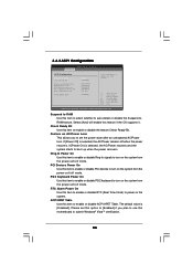
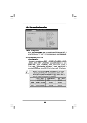
... south bridge only supports four IDE devices under legacy OS (Windows NT), you to [IDE 1, SATA 2, SATA 4], then SATAII_1, SATAII_3 will not work. 3.4.4 Storage Configuration BIOS SETUP UTILITY Advanced Storage Configuration ATA/IDE Configuration SATAII_1 SATAII_2 SATAII_3 SATAII_4 IDE1 Master IDE1 Slave [Enhanced] [Hard Disk] [Not Detected] [Not Detected] [Not Detected...
... south bridge only supports four IDE devices under legacy OS (Windows NT), you to [IDE 1, SATA 2, SATA 4], then SATAII_1, SATAII_3 will not work. 3.4.4 Storage Configuration BIOS SETUP UTILITY Advanced Storage Configuration ATA/IDE Configuration SATAII_1 SATAII_2 SATAII_3 SATAII_4 IDE1 Master IDE1 Slave [Enhanced] [Hard Disk] [Not Detected] [Not Detected] [Not Detected...
User Manual
Page 45
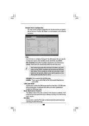
... Mode Use this item is necessary so that you can write or read data from the hard disk. After selecting the hard disk information into BIOS, use of the Primary IDE hard disk drives to enhance hard disk performance by reading or writing more data during each transfer. We will enhance... of device connected to automatically detect the hard disk drive. Storage Device Configuration You may set the storage configuration for the device that you specify. BIOS SETUP UTILITY Advanced Primary IDE Master Device Vendor Size LBA Mode Block Mode PIO Mode Async DMA Ultra DMA S.M.A.R.T.
... Mode Use this item is necessary so that you can write or read data from the hard disk. After selecting the hard disk information into BIOS, use of the Primary IDE hard disk drives to enhance hard disk performance by reading or writing more data during each transfer. We will enhance... of device connected to automatically detect the hard disk drive. Storage Device Configuration You may set the storage configuration for the device that you specify. BIOS SETUP UTILITY Advanced Primary IDE Master Device Vendor Size LBA Mode Block Mode PIO Mode Async DMA Ultra DMA S.M.A.R.T.

User Manual
Page 46
... Technology) feature. Configuration options: [Disabled], [Auto], [Enabled]. 32-Bit Data Transfer Use this item to maximize the IDE hard disk data transfer rate. 3.4.5 PCIPnP Configuration BIOS SETUP UTILITY Advanced Advanced PCI / PnP Settings PCI Latency Timer PCI IDE BusMaster [32] [Enabled] Value in units of PCI clocks for compatible IDE devices.
... Technology) feature. Configuration options: [Disabled], [Auto], [Enabled]. 32-Bit Data Transfer Use this item to maximize the IDE hard disk data transfer rate. 3.4.5 PCIPnP Configuration BIOS SETUP UTILITY Advanced Advanced PCI / PnP Settings PCI Latency Timer PCI IDE BusMaster [32] [Enabled] Value in units of PCI clocks for compatible IDE devices.


