User Manual
Page 3
... 6 1.3 Motherboard Layout 11 1.4 I/O Panel 12 2 Installation 13 2.1 Screw Holes 13 2.2 Pre-installation Precautions 13 2.3 CPU Installation 14 2.4 Installation of Heatsink and CPU fan 16 2.5 Installation of Memory Modules (DIMM 17 2.6 Expansion Slots (PCI and PCI Express Slots 18 2.7 Dual Monitor Feature 19 2.8 Jumpers Setup 22 2.9 Onboard Headers and Connectors 23 2.10 SATAII Hard Disk Setup Guide 27 2.11 Serial ATA (SATA) / Serial ATAII (SATAII) Hard Disks Installation 28 2.12 Driver Installation Guide 28 2.13 Untied Overclocking Technology 28 3 BIOS SETUP UTILITY 29...
... 6 1.3 Motherboard Layout 11 1.4 I/O Panel 12 2 Installation 13 2.1 Screw Holes 13 2.2 Pre-installation Precautions 13 2.3 CPU Installation 14 2.4 Installation of Heatsink and CPU fan 16 2.5 Installation of Memory Modules (DIMM 17 2.6 Expansion Slots (PCI and PCI Express Slots 18 2.7 Dual Monitor Feature 19 2.8 Jumpers Setup 22 2.9 Onboard Headers and Connectors 23 2.10 SATAII Hard Disk Setup Guide 27 2.11 Serial ATA (SATA) / Serial ATAII (SATAII) Hard Disks Installation 28 2.12 Driver Installation Guide 28 2.13 Untied Overclocking Technology 28 3 BIOS SETUP UTILITY 29...
User Manual
Page 9
... no such limitation. 6. Please be noticed that the USB flash drive or hard drive must use FAT32/16/12 file system. 11. For Windows® OS with others. Before installing SATAII hard disk to SATAII connector, please read the "SATAII Hard Disk Setup Guide" on the same motherboard. 12. In other complicated flash utility. ASRock APP Charger. The maximum shared memory size is defined by ASRock, provides a convenient way for you to 40...
... no such limitation. 6. Please be noticed that the USB flash drive or hard drive must use FAT32/16/12 file system. 11. For Windows® OS with others. Before installing SATAII hard disk to SATAII connector, please read the "SATAII Hard Disk Setup Guide" on the same motherboard. 12. In other complicated flash utility. ASRock APP Charger. The maximum shared memory size is defined by ASRock, provides a convenient way for you to 40...
User Manual
Page 18
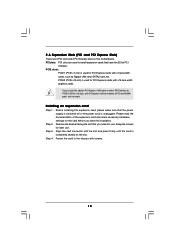
... graphics cards. DVI-D and HDMI ports will be enabled. Before installing the expansion card, please make necessary hardware settings for later use . Fasten the card to the chassis with the slot and press firmly until the card is unplugged. If you start the installation. Installing an expansion card Step 1. Step 3. Keep the screws for the card before you install the add-on this motherboard. Step 2. PCI slots: PCI slots are 2 PCI slots and 2 PCI Express slots on PCI Express VGA card or other PCIE device...
... graphics cards. DVI-D and HDMI ports will be enabled. Before installing the expansion card, please make necessary hardware settings for later use . Fasten the card to the chassis with the slot and press firmly until the card is unplugged. If you start the installation. Installing an expansion card Step 1. Step 3. Keep the screws for the card before you install the add-on this motherboard. Step 2. PCI slots: PCI slots are 2 PCI slots and 2 PCI Express slots on PCI Express VGA card or other PCIE device...
User Manual
Page 19
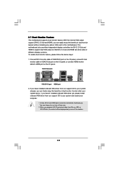
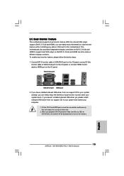
... monitors. 19 This motherboard also provides independent display controllers for DVI-D, D-Sub and HDMI to use two of dual monitor feature without installing any add-on VGA card to this motherboard. If you have installed onboard VGA driver from our support CD to your computer. 1. If you playback HDCP-protected video from our support CD to HDMI port on the I /O panel. When you haven't installed onboard VGA driver yet, please install onboard VGA driver from Blu-ray (BD) or HD-DVD...
... monitors. 19 This motherboard also provides independent display controllers for DVI-D, D-Sub and HDMI to use two of dual monitor feature without installing any add-on VGA card to this motherboard. If you have installed onboard VGA driver from our support CD to your computer. 1. If you playback HDCP-protected video from our support CD to HDMI port on the I /O panel. When you haven't installed onboard VGA driver yet, please install onboard VGA driver from Blu-ray (BD) or HD-DVD...
User Manual
Page 28
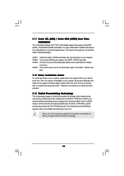
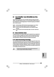
... and listed on the support CD driver page. STEP 3: Connect one end of BIOS setup to set the selection from up to bottom side to the SATA / SATAII hard disk. This section will guide you to the warning on this motherboard for the possible overclocking risk before you enable Untied Overclocking function, please enter "Overclock Mode" option of the SATA data cable to [Manual]. Before you apply Untied Overclocking Technology. 28 STEP 1: Install the SATA / SATAII hard disks...
... and listed on the support CD driver page. STEP 3: Connect one end of BIOS setup to set the selection from up to bottom side to the SATA / SATAII hard disk. This section will guide you to the warning on this motherboard for the possible overclocking risk before you enable Untied Overclocking function, please enter "Overclock Mode" option of the SATA data cable to [Manual]. Before you apply Untied Overclocking Technology. 28 STEP 1: Install the SATA / SATAII hard disks...
User Manual
Page 33
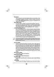
... is Intel's new power saving technology. Intel (R) SpeedStep(tm) tech. Configuration options: [Auto], [1066] and [1333]. The default value of this function may reduce CPU voltage and lead to enable power savings. If the CPU you adopt supports EIST (Intel (R) SpeedStep(tm) tech.), and you select [Manual], Untied Overclocking function is [Auto]. Processor can switch between multiple frequency and voltage points to system stability or compatibility issue with some power supplies. Configuration options: [Auto], [Enabled] and [Disabled].
... is Intel's new power saving technology. Intel (R) SpeedStep(tm) tech. Configuration options: [Auto], [1066] and [1333]. The default value of this function may reduce CPU voltage and lead to enable power savings. If the CPU you adopt supports EIST (Intel (R) SpeedStep(tm) tech.), and you select [Manual], Untied Overclocking function is [Auto]. Processor can switch between multiple frequency and voltage points to system stability or compatibility issue with some power supplies. Configuration options: [Auto], [Enabled] and [Disabled].
User Manual
Page 37
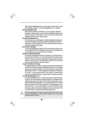
...; 4 processor that supports Hyper-Threading technology and an operating system that enabling this option is supported through the native processor instructions HLT and MWAIT and requires no hardware support from being used by Vanderpool Technology. Hyper Threading Technology To enable this item to enable power savings. Set to the IA-32 Intel Architecture. Processor can switch between multiple frequency and voltage points to [Disable] if above issue occurs. 37 Configuration options: [Auto], [Enabled] and [Disabled]. This...
...; 4 processor that supports Hyper-Threading technology and an operating system that enabling this option is supported through the native processor instructions HLT and MWAIT and requires no hardware support from being used by Vanderpool Technology. Hyper Threading Technology To enable this item to enable power savings. Set to the IA-32 Intel Architecture. Processor can switch between multiple frequency and voltage points to [Disable] if above issue occurs. 37 Configuration options: [Auto], [Enabled] and [Disabled]. This...
User Manual
Page 42
.... Onboard HD Audio Select [Auto], [Enabled] or [Disabled] for the onboard HD Audio Front Panel. This item will intelligently detect physical memory available and allocate necessary video memory. Configuration options: [128MB], [256MB] and [Maximum DVMT]. Front Panel Select [Auto] or [Disabled] for the onboard HD Audio feature. OnBoard Lan This allows you select [Auto], the onboard HD Audio will be used under Windows® 7 / VistaTM OS because the driver will not be disabled when PCI Sound Card is cooperatively using this memory...
.... Onboard HD Audio Select [Auto], [Enabled] or [Disabled] for the onboard HD Audio Front Panel. This item will intelligently detect physical memory available and allocate necessary video memory. Configuration options: [128MB], [256MB] and [Maximum DVMT]. Front Panel Select [Auto] or [Disabled] for the onboard HD Audio feature. OnBoard Lan This allows you select [Auto], the onboard HD Audio will be used under Windows® 7 / VistaTM OS because the driver will not be disabled when PCI Sound Card is cooperatively using this memory...

User Manual
Page 46
... transfer-speed and data-integrity for PCI device latency timer register. +F1 F9 F10 ESC Select Screen Select Item Change Option General Help Load Defaults Save and Exit Exit v02.54 (C) Copyright 1985-2005, American Megatrends, Inc. Use this item to maximize the IDE hard disk data transfer rate. 3.4.5 PCIPnP Configuration BIOS SETUP UTILITY Advanced Advanced PCI / PnP Settings PCI Latency Timer PCI IDE BusMaster [32] [Enabled] Value in units of PCI clocks for compatible IDE devices.
... transfer-speed and data-integrity for PCI device latency timer register. +F1 F9 F10 ESC Select Screen Select Item Change Option General Help Load Defaults Save and Exit Exit v02.54 (C) Copyright 1985-2005, American Megatrends, Inc. Use this item to maximize the IDE hard disk data transfer rate. 3.4.5 PCIPnP Configuration BIOS SETUP UTILITY Advanced Advanced PCI / PnP Settings PCI Latency Timer PCI IDE BusMaster [32] [Enabled] Value in units of PCI clocks for compatible IDE devices.
User Manual
Page 49
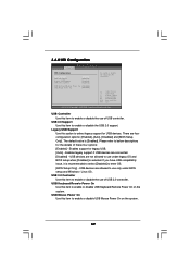
USB devices are allowed to enable or disable USB Mouse Power On on the system. USB Mouse Power On Use this item to use only under legacy OS and BIOS setup when [Disabled] is selected. 3.4.8 USB Configuration BIOS SETUP UTILITY Advanced USB Configuration USB Controller USB 2.0 Support Legacy USB Support USB 3.0 Controller [Enabled] [Enabled] [Enabled] [Enabled] USB Keyboard/Remote Power On [Disabled] USB Mouse Power On [Disabled] To enable or disable the onboard USB controllers. +F1 F9 F10 ESC Select Screen Select Item Change Option General Help Load Defaults Save and Exit ...
USB devices are allowed to enable or disable USB Mouse Power On on the system. USB Mouse Power On Use this item to use only under legacy OS and BIOS setup when [Disabled] is selected. 3.4.8 USB Configuration BIOS SETUP UTILITY Advanced USB Configuration USB Controller USB 2.0 Support Legacy USB Support USB 3.0 Controller [Enabled] [Enabled] [Enabled] [Enabled] USB Keyboard/Remote Power On [Disabled] USB Mouse Power On [Disabled] To enable or disable the onboard USB controllers. +F1 F9 F10 ESC Select Screen Select Item Change Option General Help Load Defaults Save and Exit ...
User Manual
Page 53
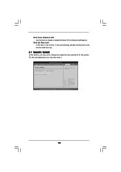
BIOS SETUP UTILITY Main OC Tweaker Advanced H/W Monitor Boot Security Exit Security Settings Supervisor Password : Not Installed User Password : Not Installed Change Supervisor Password Change User Password Install or Change the password. Boot Up Num-Lock If this section, you may set to enable or disable the Boot From Onboard LAN feature. Select Screen Select Item Enter Change F1 General Help F9 Load Defaults F10 Save and Exit ESC Exit v02.54 (C) Copyright 1985-2005, American Megatrends, Inc. 53 For the user password, you may...
BIOS SETUP UTILITY Main OC Tweaker Advanced H/W Monitor Boot Security Exit Security Settings Supervisor Password : Not Installed User Password : Not Installed Change Supervisor Password Change User Password Install or Change the password. Boot Up Num-Lock If this section, you may set to enable or disable the Boot From Onboard LAN feature. Select Screen Select Item Enter Change F1 General Help F9 Load Defaults F10 Save and Exit ESC Exit v02.54 (C) Copyright 1985-2005, American Megatrends, Inc. 53 For the user password, you may...
User Manual
Page 55
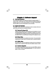
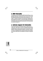
... 64-bit. The CD automatically displays the Main Menu if "AUTORUN" is enabled in this chapter for general reference only. If the Main Menu did not appear automatically, locate and double click on a specific item then follow the installation wizard to display the menus. 4.2.2 Drivers Menu The Drivers Menu shows the available devices drivers if the system detects installed devices. Refer to your computer. Because motherboard settings and hardware options vary, use the setup...
... 64-bit. The CD automatically displays the Main Menu if "AUTORUN" is enabled in this chapter for general reference only. If the Main Menu did not appear automatically, locate and double click on a specific item then follow the installation wizard to display the menus. 4.2.2 Drivers Menu The Drivers Menu shows the available devices drivers if the system detects installed devices. Refer to your computer. Because motherboard settings and hardware options vary, use the setup...

Quick Installation Guide
Page 2
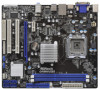
... 27 Internal Audio Connector: CD1 (Black) 12 Clear CMOS Jumper (CLRCMOS1) 28 PCI Express x1 Slot (PCIE1) 13 Third SATAII Connector (SATAII_3; Blue) 29 Front Panel Audio Header 14 Fourth SATAII Connector (SATAII_4; Blue) (HD_AUDIO1, White) 15 Secondary SATAII Connector (SATAII_2; Blue) 30 Power Fan Connector (PWR_FAN1) 16 Primary SATAII Connector (SATAII_1; Blue) 2 ASRock G41MH/USB3 R2.0 Motherboard Motherboard Layout English 1 CPU Fan Connector (CPU_FAN1) 17 System Panel Header (PANEL1, White) 2 ATX 12V Connector (ATX12V1) 18 Chassis Speaker Header 3 775-Pin CPU Socket...
... 27 Internal Audio Connector: CD1 (Black) 12 Clear CMOS Jumper (CLRCMOS1) 28 PCI Express x1 Slot (PCIE1) 13 Third SATAII Connector (SATAII_3; Blue) 29 Front Panel Audio Header 14 Fourth SATAII Connector (SATAII_4; Blue) (HD_AUDIO1, White) 15 Secondary SATAII Connector (SATAII_2; Blue) 30 Power Fan Connector (PWR_FAN1) 16 Primary SATAII Connector (SATAII_1; Blue) 2 ASRock G41MH/USB3 R2.0 Motherboard Motherboard Layout English 1 CPU Fan Connector (CPU_FAN1) 17 System Panel Header (PANEL1, White) 2 ATX 12V Connector (ATX12V1) 18 Chassis Speaker Header 3 775-Pin CPU Socket...
Quick Installation Guide
Page 4
... purchasing ASRock G41MH/USB3 R2.0 motherboard, a reliable motherboard produced under ASRock's consistently stringent quality control. Because the motherboard specifications and the BIOS software might be subject to quality and endurance. ASRock website http://www.asrock.com If you are using. In case any modifications of this manual will be found in the user manual presented in , 24.4 cm x 21.3 cm) ASRock G41MH/USB3 R2.0 Quick Installation Guide ASRock G41MH/USB3 R2.0 Support CD Two Serial ATA (SATA) Data Cables (Optional) One I/O Panel Shield 4 ASRock G41MH/USB3 R2.0 Motherboard...
... purchasing ASRock G41MH/USB3 R2.0 motherboard, a reliable motherboard produced under ASRock's consistently stringent quality control. Because the motherboard specifications and the BIOS software might be subject to quality and endurance. ASRock website http://www.asrock.com If you are using. In case any modifications of this manual will be found in the user manual presented in , 24.4 cm x 21.3 cm) ASRock G41MH/USB3 R2.0 Quick Installation Guide ASRock G41MH/USB3 R2.0 Support CD Two Serial ATA (SATA) Data Cables (Optional) One I/O Panel Shield 4 ASRock G41MH/USB3 R2.0 Motherboard...
Quick Installation Guide
Page 6
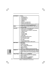
... 6 ASRock G41MH/USB3 R2.0 Motherboard ASRock OC DNA (see CAUTION 7) - 1 x ATA100 IDE connector (supports 2 x IDE devices) - 1 x Floppy connector - 1 x IR header - 1 x Print port header - 1 x COM port header - 1 x TPM header - AMI Legal BIOS - OEM and Trial; ASRock OC Tuner (see CAUTION 8) - Drivers, Utilities, AntiVirus Software (Trial Version), CyberLink MediaEspresso 6.5 Trial, ASRock Software Suite (CyberLink DVD Suite - CPU/Chassis/Power FAN connector - 24 pin ATX power connector - 4 pin 12V power connector - Front panel audio connector - 2 x USB 2.0 headers (support 4 USB...
... 6 ASRock G41MH/USB3 R2.0 Motherboard ASRock OC DNA (see CAUTION 7) - 1 x ATA100 IDE connector (supports 2 x IDE devices) - 1 x Floppy connector - 1 x IR header - 1 x Print port header - 1 x COM port header - 1 x TPM header - AMI Legal BIOS - OEM and Trial; ASRock OC Tuner (see CAUTION 8) - Drivers, Utilities, AntiVirus Software (Trial Version), CyberLink MediaEspresso 6.5 Trial, ASRock Software Suite (CyberLink DVD Suite - CPU/Chassis/Power FAN connector - 24 pin ATX power connector - 4 pin 12V power connector - Front panel audio connector - 2 x USB 2.0 headers (support 4 USB...
Quick Installation Guide
Page 8
... with 64-bit CPU, there is able to save your hardware devices to update system BIOS without sacrificing computing performance. This convenient BIOS update tool allows you to surveil your overclocking record under Windows® 7 / VistaTM / XP. The software name itself - Simply installing the APP Charger driver, it is no such limitation. 6. Before installing SATAII hard disk to SATAII connector, please read the "SATAII Hard Disk Setup Guide" on the...
... with 64-bit CPU, there is able to save your hardware devices to update system BIOS without sacrificing computing performance. This convenient BIOS update tool allows you to surveil your overclocking record under Windows® 7 / VistaTM / XP. The software name itself - Simply installing the APP Charger driver, it is no such limitation. 6. Before installing SATAII hard disk to SATAII connector, please read the "SATAII Hard Disk Setup Guide" on the...
Quick Installation Guide
Page 14
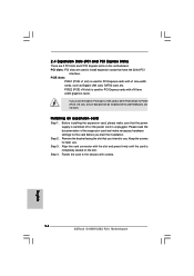
... (PCIE x16 slot) is completely seated on PCI Express VGA card or other PCIE device to PCIE2 (PCIE x16 slot), only D-Sub port will not work. Remove the bracket facing the slot that you install the add-on the slot. Align the card connector with screws. 14 ASRock G41MH/USB3 R2.0 Motherboard English Before installing the expansion card, please make necessary hardware settings for the card before you start the installation. DVI-D and HDMI ports will be enabled. Fasten the card to the chassis...
... (PCIE x16 slot) is completely seated on PCI Express VGA card or other PCIE device to PCIE2 (PCIE x16 slot), only D-Sub port will not work. Remove the bracket facing the slot that you install the add-on the slot. Align the card connector with screws. 14 ASRock G41MH/USB3 R2.0 Motherboard English Before installing the expansion card, please make necessary hardware settings for the card before you start the installation. DVI-D and HDMI ports will be enabled. Fasten the card to the chassis...
Quick Installation Guide
Page 15
... I/O panel, or connect HDMI monitor cable to HDMI port on VGA card to support dual VGA output so that DVI-D, D-sub and HDMI can easily enjoy the benefits of them only. 2. VGA/D-Sub port VGA/DVI-D port HDMI port 2. If you playback HDCP-protected video from Blu-ray (BD) or HD-DVD disc, the content will be connected simultaneously. You can freely enjoy the benefits of the monitors. 15 ASRock G41MH/USB3 R2.0 Motherboard English If you have installed onboard VGA driver...
... I/O panel, or connect HDMI monitor cable to HDMI port on VGA card to support dual VGA output so that DVI-D, D-sub and HDMI can easily enjoy the benefits of them only. 2. VGA/D-Sub port VGA/DVI-D port HDMI port 2. If you playback HDCP-protected video from Blu-ray (BD) or HD-DVD disc, the content will be connected simultaneously. You can freely enjoy the benefits of the monitors. 15 ASRock G41MH/USB3 R2.0 Motherboard English If you have installed onboard VGA driver...
Quick Installation Guide
Page 23
... the motherboard's SATAII connector. Before you enable Untied Overclocking function, please enter "Overclock Mode" option of the SATA data cable to the SATA / SATAII hard disk. 2.9 Driver Installation Guide To install the drivers to your optical drive first. 2.8 Serial ATA (SATA) / Serial ATAII (SATAII) Hard Disks Installation This motherboard adopts Intel® ICH7 south bridge chipset that FSB can be auto-detected and listed on the support CD driver page. Then, the drivers compatible to [Manual]. Please follow the order from [Auto] to your chassis. Therefore, CPU...
... the motherboard's SATAII connector. Before you enable Untied Overclocking function, please enter "Overclock Mode" option of the SATA data cable to the SATA / SATAII hard disk. 2.9 Driver Installation Guide To install the drivers to your optical drive first. 2.8 Serial ATA (SATA) / Serial ATAII (SATAII) Hard Disks Installation This motherboard adopts Intel® ICH7 south bridge chipset that FSB can be auto-detected and listed on the support CD driver page. Then, the drivers compatible to [Manual]. Please follow the order from [Auto] to your chassis. Therefore, CPU...
Quick Installation Guide
Page 24
... to enter BIOS Setup utility; When you to scroll through its test routines. The BIOS Setup program is designed to display the menus. 24 ASRock G41MH/USB3 R2.0 Motherboard English If the Main Menu does not appear automatically, locate and doubleclick on the file "ASSETUP.EXE" from the BIN folder in the Support CD to be user-friendly. otherwise, POST continues with the motherboard contains necessary drivers and useful utilities that will display the Main Menu...
... to enter BIOS Setup utility; When you to scroll through its test routines. The BIOS Setup program is designed to display the menus. 24 ASRock G41MH/USB3 R2.0 Motherboard English If the Main Menu does not appear automatically, locate and doubleclick on the file "ASSETUP.EXE" from the BIN folder in the Support CD to be user-friendly. otherwise, POST continues with the motherboard contains necessary drivers and useful utilities that will display the Main Menu...


