User Manual
Page 6
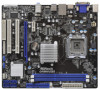
... (1080P) - PCIE x1 Gigabit LAN 10/100/1000 Mb/s - Supports LAN Cable Detection - Supports Untied Overclocking Technology (see CAUTION 1) - resolution up to 1920x1200 @ 75Hz - LGA 775 for CPU power - Northbridge: Intel® G41 - Three VGA Output options: D-Sub, DVI-D and HDMI - Supports DVI with DVI and HDMI ports - 5.1 CH HD Audio...
... (1080P) - PCIE x1 Gigabit LAN 10/100/1000 Mb/s - Supports LAN Cable Detection - Supports Untied Overclocking Technology (see CAUTION 1) - resolution up to 1920x1200 @ 75Hz - LGA 775 for CPU power - Northbridge: Intel® G41 - Three VGA Output options: D-Sub, DVI-D and HDMI - Supports DVI with DVI and HDMI ports - 5.1 CH HD Audio...
User Manual
Page 11
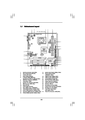
...6 DDR3_B1 (64 bit, 240-pin module) DDR3_A1 (64 bit, 240-pin module) HDMI1 24.4cm (9.6 in) G41MH/USB3 29 LAN PHY USB 2.0 T: USB0 B: USB1 Top: RJ-45 USB 3.0 T: USB2 B: USB3 HD_AUDIO1 Intel G41 Chipset TPM1 1 7 CHA_FAN1 8 1 ErP/EuP Ready Gigabit LAN Top: LINE IN Center: FRONT ...21 20 19 18 17 16 1 CPU Fan Connector (CPU_FAN1) 17 System Panel Header (PANEL1, White) 2 ATX 12V Connector (ATX12V1) 18 Chassis Speaker Header 3 775-Pin CPU Socket (SPEAKER 1, White) 4 North Bridge Controller 19 USB 2.0 Header (USB6_7, Blue) 5 2 x 240-pin DDR3 DIMM Slots 20 USB 2.0 Header...
...6 DDR3_B1 (64 bit, 240-pin module) DDR3_A1 (64 bit, 240-pin module) HDMI1 24.4cm (9.6 in) G41MH/USB3 29 LAN PHY USB 2.0 T: USB0 B: USB1 Top: RJ-45 USB 3.0 T: USB2 B: USB3 HD_AUDIO1 Intel G41 Chipset TPM1 1 7 CHA_FAN1 8 1 ErP/EuP Ready Gigabit LAN Top: LINE IN Center: FRONT ...21 20 19 18 17 16 1 CPU Fan Connector (CPU_FAN1) 17 System Panel Header (PANEL1, White) 2 ATX 12V Connector (ATX12V1) 18 Chassis Speaker Header 3 775-Pin CPU Socket (SPEAKER 1, White) 4 North Bridge Controller 19 USB 2.0 Header (USB6_7, Blue) 5 2 x 240-pin DDR3 DIMM Slots 20 USB 2.0 Header...
User Manual
Page 14
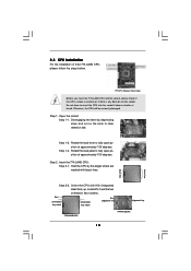
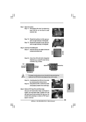
... the load lever to fully open position at approximately 135 degrees. Pin1 orientation key notch orientation key notch Pin1 alignment key alignment key 775-LAND CPU 775-Pin Socket 14 black line black line Step 1. Step 2-2. Step 1-3. Rotate the load plate to fully open position at approximately 100... Otherwise, the CPU will be seriously damaged. 2.3 CPU Installation For the installation of Intel 775-LAND CPU, please follow the steps below. 775-Pin Socket Overview Before you insert the 775-LAND CPU into the socket if above situation is any bent pin on the hook to ...
... the load lever to fully open position at approximately 135 degrees. Pin1 orientation key notch orientation key notch Pin1 alignment key alignment key 775-LAND CPU 775-Pin Socket 14 black line black line Step 1. Step 2-2. Step 1-3. Rotate the load plate to fully open position at approximately 100... Otherwise, the CPU will be seriously damaged. 2.3 CPU Installation For the installation of Intel 775-LAND CPU, please follow the steps below. 775-Pin Socket Overview Before you insert the 775-LAND CPU into the socket if above situation is any bent pin on the hook to ...

User Manual
Page 16
...rotating them clockwise, the heatsink cannot be secured on the motherboard (CPU_FAN1, see page 11, No. 1). Step 2. Ensure that supports Intel 775-LAND CPU. Apply thermal interface material onto center of IHS on fastener caps with thumb to illustrate the installation of CPU Fan and Heatsink This... motherboard is equipped with 775-Pin socket that the CPU and the heatsink are oriented on side closest to the CPU_FAN connector (CPU_FAN1, see page 11, No. 1)....
...rotating them clockwise, the heatsink cannot be secured on the motherboard (CPU_FAN1, see page 11, No. 1). Step 2. Ensure that supports Intel 775-LAND CPU. Apply thermal interface material onto center of IHS on fastener caps with thumb to illustrate the installation of CPU Fan and Heatsink This... motherboard is equipped with 775-Pin socket that the CPU and the heatsink are oriented on side closest to the CPU_FAN connector (CPU_FAN1, see page 11, No. 1)....

Quick Installation Guide
Page 2
... 12V Connector (ATX12V1) 18 Chassis Speaker Header 3 775-Pin CPU Socket (SPEAKER 1, White) 4 North Bridge Controller 19 USB 2.0 Header (USB6_7, Blue) 5 2 x 240-pin DDR3 DIMM Slots 20 USB 2.0 Header (USB4_5, Blue) (Dual Channel: DDR3_A1, DDR3_B1; Blue) (HD_AUDIO1, White) 15 Secondary SATAII Connector (SATAII_2; Blue) 2 ASRock G41MH/USB3 R2.0 Motherboard Blue) 21 Infrared Module Header (IR1...
... 12V Connector (ATX12V1) 18 Chassis Speaker Header 3 775-Pin CPU Socket (SPEAKER 1, White) 4 North Bridge Controller 19 USB 2.0 Header (USB6_7, Blue) 5 2 x 240-pin DDR3 DIMM Slots 20 USB 2.0 Header (USB4_5, Blue) (Dual Channel: DDR3_A1, DDR3_B1; Blue) (HD_AUDIO1, White) 15 Secondary SATAII Connector (SATAII_2; Blue) 2 ASRock G41MH/USB3 R2.0 Motherboard Blue) 21 Infrared Module Header (IR1...
Quick Installation Guide
Page 5
... Intel® Graphics Media Accelerator X4500 - Supports DVI with max. Dual Channel DDR3 Memory Technology (see CAUTION 1) - Realtek RTL8111E - Supports PXE 5 ASRock G41MH/USB3 R2.0 Motherboard English Solid Capacitor for Intel® CoreTM 2 Extreme / CoreTM 2 Quad / CoreTM 2 Duo / Pentium® Dual Core / Celeron®... Supports Full HD 1080p Blu-ray (BD) / HD-DVD playback with DVI and HDMI ports - Supports D-Sub with max. LGA 775 for CPU power - Pixel Shader 4.0, DirectX 10 - Northbridge: Intel® G41 - Supports Energy Efficient Ethernet 802.3az - capacity ...
... Intel® Graphics Media Accelerator X4500 - Supports DVI with max. Dual Channel DDR3 Memory Technology (see CAUTION 1) - Realtek RTL8111E - Supports PXE 5 ASRock G41MH/USB3 R2.0 Motherboard English Solid Capacitor for Intel® CoreTM 2 Extreme / CoreTM 2 Quad / CoreTM 2 Duo / Pentium® Dual Core / Celeron®... Supports Full HD 1080p Blu-ray (BD) / HD-DVD playback with DVI and HDMI ports - Supports D-Sub with max. LGA 775 for CPU power - Pixel Shader 4.0, DirectX 10 - Northbridge: Intel® G41 - Supports Energy Efficient Ethernet 802.3az - capacity ...

Quick Installation Guide
Page 10
... or if there is found. Also remember to the motherboard, peripherals, and/or components. 2. Otherwise, the CPU will be seriously damaged. 10 ASRock G41MH/USB3 R2.0 Motherboard English Hold components by the edges and do not over-tighten the screws! Doing so may cause severe damage to use a grounded wrist ... place it on the carpet or the like. 2. Failure to the chassis, please do not touch the ICs. 4. Whenever you insert the 775-LAND CPU into the screw holes to secure the motherboard to do so may damage the motherboard. 2.1 CPU Installation For the installation of the ...
... or if there is found. Also remember to the motherboard, peripherals, and/or components. 2. Otherwise, the CPU will be seriously damaged. 10 ASRock G41MH/USB3 R2.0 Motherboard English Hold components by the edges and do not over-tighten the screws! Doing so may cause severe damage to use a grounded wrist ... place it on the carpet or the like. 2. Failure to the chassis, please do not touch the ICs. 4. Whenever you insert the 775-LAND CPU into the screw holes to secure the motherboard to do so may damage the motherboard. 2.1 CPU Installation For the installation of the ...
Quick Installation Guide
Page 11
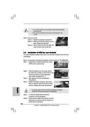
... and Place Cap): Use your left hand index finger and thumb to assist in removal. 11 ASRock G41MH/USB3 R2.0 Motherboard English Step 2. Pin1 orientation key notch orientation key notch Pin1 alignment key alignment key 775-LAND CPU 775-Pin Socket For proper inserting, please ensure to match the two orientation key notches of the CPU...
... and Place Cap): Use your left hand index finger and thumb to assist in removal. 11 ASRock G41MH/USB3 R2.0 Motherboard English Step 2. Pin1 orientation key notch orientation key notch Pin1 alignment key alignment key 775-LAND CPU 775-Pin Socket For proper inserting, please ensure to match the two orientation key notches of the CPU...
Quick Installation Guide
Page 12
... (CPU_FAN1, see page 2, No. 1). Align fasteners with fan operation or contact other components. 12 ASRock G41MH/USB3 R2.0 Motherboard If you press down the fasteners without rotating them clockwise, the heatsink cannot be placed if returning the motherboard for 775-LAND CPU. Connect fan header with load plate tab under retention tab of load lever...
... (CPU_FAN1, see page 2, No. 1). Align fasteners with fan operation or contact other components. 12 ASRock G41MH/USB3 R2.0 Motherboard If you press down the fasteners without rotating them clockwise, the heatsink cannot be placed if returning the motherboard for 775-LAND CPU. Connect fan header with load plate tab under retention tab of load lever...