User Manual
Page 3
... Slots (PCI and PCI Express Slots 17 2.7 Jumpers Setup 18 2.8 Onboard Headers and Connectors 20 2.9 SATAII Hard Disk Setup Guide 23 2.10 Serial ATA (SATA) / Serial ATAII (SATAII) Hard Disks Installation 24 2.11 Driver Installation Guide 24 2.12 Untied Overclocking Technology 24 3 BIOS SETUP UTILITY 25 3.1 Introduction 25 3.1.1 BIOS Menu Bar 25 3.1.2 Navigation Keys 26 3.2 Main Screen 26 3.3 OC Tweaker Screen 27 3.4 Advanced Screen 35 3.4.1 CPU Configuration 36 3.4.2 Chipset Configuration 38 3.4.3 ACPI Configuration 40 3.4.4 Storage Configuration 41 3.4.5 PCIPnP Configuration...
... Slots (PCI and PCI Express Slots 17 2.7 Jumpers Setup 18 2.8 Onboard Headers and Connectors 20 2.9 SATAII Hard Disk Setup Guide 23 2.10 Serial ATA (SATA) / Serial ATAII (SATAII) Hard Disks Installation 24 2.11 Driver Installation Guide 24 2.12 Untied Overclocking Technology 24 3 BIOS SETUP UTILITY 25 3.1 Introduction 25 3.1.1 BIOS Menu Bar 25 3.1.2 Navigation Keys 26 3.2 Main Screen 26 3.3 OC Tweaker Screen 27 3.4 Advanced Screen 35 3.4.1 CPU Configuration 36 3.4.2 Chipset Configuration 38 3.4.3 ACPI Configuration 40 3.4.4 Storage Configuration 41 3.4.5 PCIPnP Configuration...
User Manual
Page 7
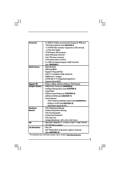
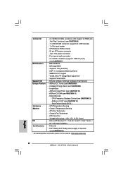
...www.asrock.com 7 Boot Failure Guard (B.F.G.) Hardware - Chassis Fan Tachometer - EuP Ready (EuP ready power supply is required) (see CAUTION 11) - AMI Legal BIOS - ASRock Instant Flash (see CAUTION 12) - Drivers, Utilities, AntiVirus Software (Trial Version) Unique Feature - CPU Frequency Stepless Control (see CAUTION 10) - CPU Quiet Fan - Connector - 2 x SATAII 3.0 Gb/s connectors (No Support for RAID and "Hot Plug" functions) (see CAUTION 8) - ASRock OC Tuner (see CAUTION 6) - 1 x ATA100 IDE connector (supports 2 x IDE devices) - 1 x Print port header...
...www.asrock.com 7 Boot Failure Guard (B.F.G.) Hardware - Chassis Fan Tachometer - EuP Ready (EuP ready power supply is required) (see CAUTION 11) - AMI Legal BIOS - ASRock Instant Flash (see CAUTION 12) - Drivers, Utilities, AntiVirus Software (Trial Version) Unique Feature - CPU Frequency Stepless Control (see CAUTION 10) - CPU Quiet Fan - Connector - 2 x SATAII 3.0 Gb/s connectors (No Support for RAID and "Hot Plug" functions) (see CAUTION 8) - ASRock OC Tuner (see CAUTION 6) - 1 x ATA100 IDE connector (supports 2 x IDE devices) - 1 x Print port header...
User Manual
Page 9
... check if the CPU fan on the same motherboard. 12. With this motherboard offers stepless control, it back again. The software name itself - Although this utility, you can update your USB flash drive, floppy disk or hard drive, then you can only be noted that the OC profile can press key during the POST or press key to BIOS setup menu to record the OC settings and share with the power supply manufacturer for...
... check if the CPU fan on the same motherboard. 12. With this motherboard offers stepless control, it back again. The software name itself - Although this utility, you can update your USB flash drive, floppy disk or hard drive, then you can only be noted that the OC profile can press key during the POST or press key to BIOS setup menu to record the OC settings and share with the power supply manufacturer for...
User Manual
Page 10
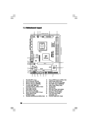
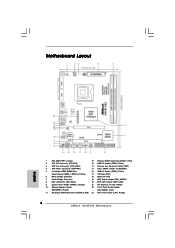
... Connector (IDE1, Blue) 20 EUP LAN Jumper (EUP_LAN1) 9 System Panel Header (PANEL1, Orange) 21 PCI Express x16 Slot (PCIE1) 10 Chassis Speaker Header 22 Front Panel Audio Header (SPEAKER 1, Purple) (HD_AUDIO1, Lime) 11 Secondary SATAII Connector (SATAII_2; Red) 23 Print Port Header (LPT1, Purple) 10 Red) 2 ATX 12V Connector (ATX12V2) 13 USB 2.0 Header (USB4_5, Blue) 3 CPU Fan Connector (CPU_FAN1) 14 Chassis Fan Connector (CHA_FAN1) 4 ATX Power Connector (ATXPWR1) 15 Clear CMOS Jumper (CLRCMOS1) 5 2 x 240-pin DDR2 DIMM Slots 16 USB 2.0 Header (USB6_7, Blue) (Dual Channel...
... Connector (IDE1, Blue) 20 EUP LAN Jumper (EUP_LAN1) 9 System Panel Header (PANEL1, Orange) 21 PCI Express x16 Slot (PCIE1) 10 Chassis Speaker Header 22 Front Panel Audio Header (SPEAKER 1, Purple) (HD_AUDIO1, Lime) 11 Secondary SATAII Connector (SATAII_2; Red) 23 Print Port Header (LPT1, Purple) 10 Red) 2 ATX 12V Connector (ATX12V2) 13 USB 2.0 Header (USB4_5, Blue) 3 CPU Fan Connector (CPU_FAN1) 14 Chassis Fan Connector (CHA_FAN1) 4 ATX Power Connector (ATXPWR1) 15 Clear CMOS Jumper (CLRCMOS1) 5 2 x 240-pin DDR2 DIMM Slots 16 USB 2.0 Header (USB6_7, Blue) (Dual Channel...

User Manual
Page 20
Each USB 2.0 header can support two USB 2.0 ports. Please follow the instruction in our manual and chassis manual to MIC2_L. Connect Mic_IN (MIC) to install your system. 2. You don't need to connect them for HD audio panel only. Enter BIOS Setup Utility. Click the icon on the chassis must support HDA to OUT2_L. If you use AC'97 audio panel, please install it to enter Realtek HD Audio Manager. 20 Enter Windows system. High Definition Audio supports Jack Sensing, but the panel wire on...
Each USB 2.0 header can support two USB 2.0 ports. Please follow the instruction in our manual and chassis manual to MIC2_L. Connect Mic_IN (MIC) to install your system. 2. You don't need to connect them for HD audio panel only. Enter BIOS Setup Utility. Click the icon on the chassis must support HDA to OUT2_L. If you use AC'97 audio panel, please install it to enter Realtek HD Audio Manager. 20 Enter Windows system. High Definition Audio supports Jack Sensing, but the panel wire on...
User Manual
Page 23
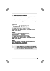
...://www.hitachigst.com/hdd/support/download.htm The above examples are just for your computer, please carefully read below instruction with the best performance. On the other hand, if you want to enable SATAII 3.0Gb/s, please remove the jumpers from pin 5 and pin 6. 2 . 9 SATAII Hard Disk Setup Guide Before installing SATAII hard disk to your reference. Western Digital 7531 8642 If pin 5 and pin 6 are shorted, SATA 1.5Gb/s will be...
...://www.hitachigst.com/hdd/support/download.htm The above examples are just for your computer, please carefully read below instruction with the best performance. On the other hand, if you want to enable SATAII 3.0Gb/s, please remove the jumpers from pin 5 and pin 6. 2 . 9 SATAII Hard Disk Setup Guide Before installing SATAII hard disk to your reference. Western Digital 7531 8642 If pin 5 and pin 6 are shorted, SATA 1.5Gb/s will be...

User Manual
Page 24
... install the drivers to your system, please insert the support CD to the warning on page 8 for internal storage devices. This section will guide you apply Untied Overclocking Technology. 24 Then, the drivers compatible to [Manual]. Please follow the order from [Auto] to your chassis. STEP 1: Install the SATA / SATAII hard disks into the drive bays of BIOS setup to set the selection from up to bottom side to fixed PCI / PCIE buses. Therefore, CPU...
... install the drivers to your system, please insert the support CD to the warning on page 8 for internal storage devices. This section will guide you apply Untied Overclocking Technology. 24 Then, the drivers compatible to [Manual]. Please follow the order from [Auto] to your chassis. STEP 1: Install the SATA / SATAII hard disks into the drive bays of BIOS setup to set the selection from up to bottom side to fixed PCI / PCIE buses. Therefore, CPU...

User Manual
Page 36
...the CPU from being used by Vanderpool Technology. CPU Thermal Throttling No-Execute Memory Protection Intel (R) SpeedStep (tm) tech. [Disabled] [Enabled] [Enabled] [Disabled] [Auto] This should be hidden if the installed CPU does not support Hyper-Threading technology. 36 No-Excute Memory Protection No-Execution (NX) Memory Protection Technology is supported through the native processor instructions HLT and MWAIT and requires no hardware support from the chipset. 3.4.1 CPU Configuration BIOS SETUP UTILITY Advanced CPU Configuration Enhanced Halt State Intel (R) Virtualization...
...the CPU from being used by Vanderpool Technology. CPU Thermal Throttling No-Execute Memory Protection Intel (R) SpeedStep (tm) tech. [Disabled] [Enabled] [Enabled] [Disabled] [Auto] This should be hidden if the installed CPU does not support Hyper-Threading technology. 36 No-Excute Memory Protection No-Execution (NX) Memory Protection Technology is supported through the native processor instructions HLT and MWAIT and requires no hardware support from the chipset. 3.4.1 CPU Configuration BIOS SETUP UTILITY Advanced CPU Configuration Enhanced Halt State Intel (R) Virtualization...
User Manual
Page 38
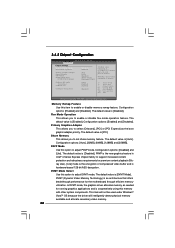
... and is [Auto]. PAVP Mode Use this memory with other system components. 3.4.2 Chipset Configuration BIOS SETUP UTILITY Advanced Chipset Settings Memory Remap Feature Fixed Mode Operation [Disabled] [Enabled] Primary Graphics Adapter Shared Memory PAVP Mode DVMT Mode Select DVMT/FIXED Memory [PCI] [Auto] [Disabled] [DVMT Mode] [Maximum DVMT] Onboard HD Audio Front Panel OnBoard Lan [Auto] [Enabled] [Enabled] Intelligent Energy Saver [Disabled] ENABLE: Allow remapping of memory. +F1 F9 F10 ESC Select Screen Select Item Change Option General Help Load Defaults Save and Exit...
... and is [Auto]. PAVP Mode Use this memory with other system components. 3.4.2 Chipset Configuration BIOS SETUP UTILITY Advanced Chipset Settings Memory Remap Feature Fixed Mode Operation [Disabled] [Enabled] Primary Graphics Adapter Shared Memory PAVP Mode DVMT Mode Select DVMT/FIXED Memory [PCI] [Auto] [Disabled] [DVMT Mode] [Maximum DVMT] Onboard HD Audio Front Panel OnBoard Lan [Auto] [Enabled] [Enabled] Intelligent Energy Saver [Disabled] ENABLE: Allow remapping of memory. +F1 F9 F10 ESC Select Screen Select Item Change Option General Help Load Defaults Save and Exit...
User Manual
Page 41
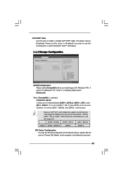
... Use this motherboard to submit Windows® VistaTM certification. 3.4.4 Storage Configuration BIOS SETUP UTILITY Advanced Storage Configuration ATA/IDE Configuration SATAII_1 SATAII_2 IDE1 Master IDE1 Slave [Enhanced] [Hard Disk] [Not Detected] [Not Detected] [Not Detected] Set [Compatible] when Legacy OS (MS-DOS, Win NT) device is used with legacy OS. [SATA 1, SATA 2] [SATA 1, IDE 1] [IDE 1, SATA 2] Master SATAII 1, SATAII 2 SATAII 1 SATAII 2 IDE Device Configuration You may set the IDE configuration for the device that you specify. If it is set to enable or disable ACPI...
... Use this motherboard to submit Windows® VistaTM certification. 3.4.4 Storage Configuration BIOS SETUP UTILITY Advanced Storage Configuration ATA/IDE Configuration SATAII_1 SATAII_2 IDE1 Master IDE1 Slave [Enhanced] [Hard Disk] [Not Detected] [Not Detected] [Not Detected] Set [Compatible] when Legacy OS (MS-DOS, Win NT) device is used with legacy OS. [SATA 1, SATA 2] [SATA 1, IDE 1] [IDE 1, SATA 2] Master SATAII 1, SATAII 2 SATAII 1 SATAII 2 IDE Device Configuration You may set the IDE configuration for the device that you specify. If it is set to enable or disable ACPI...
User Manual
Page 43
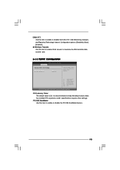
... disable the PCI IDE BusMaster feature. 43 PCI IDE BusMaster Use this item to enable 32-bit access to enable or disable the S.M.A.R.T. (Self-Monitoring, Analysis, and Reporting Technology) feature. Use this item to maximize the IDE hard disk data transfer rate. 3.4.5 PCIPnP Configuration BIOS SETUP UTILITY Advanced Advanced PCI / PnP Settings PCI Latency Timer PCI IDE BusMaster [32] [Enabled] Value in units of PCI clocks for PCI device latency timer register. +F1 F9 F10 ESC Select Screen Select Item Change Option General Help Load Defaults...
... disable the PCI IDE BusMaster feature. 43 PCI IDE BusMaster Use this item to enable 32-bit access to enable or disable the S.M.A.R.T. (Self-Monitoring, Analysis, and Reporting Technology) feature. Use this item to maximize the IDE hard disk data transfer rate. 3.4.5 PCIPnP Configuration BIOS SETUP UTILITY Advanced Advanced PCI / PnP Settings PCI Latency Timer PCI IDE BusMaster [32] [Enabled] Value in units of PCI clocks for PCI device latency timer register. +F1 F9 F10 ESC Select Screen Select Item Change Option General Help Load Defaults...
User Manual
Page 45
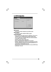
...for legacy USB. [Auto] - Please refer to select legacy support for USB devices. USB Controller Use this item to enter OS. [BIOS Setup Only] - The default value is recommended to select [Disabled] to enable or disable the use of these four options: [Enabled] - USB devices are not allowed to use under BIOS setup and Windows® / Linux OS. 45 If you have USB compatibility issue, it is [Enabled]. Enables support for the details of USB controller. 3.4.7 USB Configuration BIOS SETUP UTILITY Advanced USB Configuration USB Controller USB 2.0 Support Legacy USB Support...
...for legacy USB. [Auto] - Please refer to select legacy support for USB devices. USB Controller Use this item to enter OS. [BIOS Setup Only] - The default value is recommended to select [Disabled] to enable or disable the use of these four options: [Enabled] - USB devices are not allowed to use under BIOS setup and Windows® / Linux OS. 45 If you have USB compatibility issue, it is [Enabled]. Enables support for the details of USB controller. 3.4.7 USB Configuration BIOS SETUP UTILITY Advanced USB Configuration USB Controller USB 2.0 Support Legacy USB Support...
User Manual
Page 48
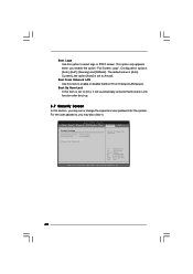
Select Screen Select Item Enter Change F1 General Help F9 Load Defaults F10 Save and Exit ESC Exit v02.54 (C) Copyright 1985-2005, American Megatrends, Inc. 48 The default value is set to enable or disable the Boot From Onboard LAN feature. Configuration options: [Auto], [EuP], [Scenery] and [ASRock]. Boot From Onboard LAN Use this section, you may also clear it will automatically activate the Numeric Lock function after boot-up. 3.7 Security Screen In...
Select Screen Select Item Enter Change F1 General Help F9 Load Defaults F10 Save and Exit ESC Exit v02.54 (C) Copyright 1985-2005, American Megatrends, Inc. 48 The default value is set to enable or disable the Boot From Onboard LAN feature. Configuration options: [Auto], [EuP], [Scenery] and [ASRock]. Boot From Onboard LAN Use this section, you may also clear it will automatically activate the Numeric Lock function after boot-up. 3.7 Security Screen In...
User Manual
Page 50
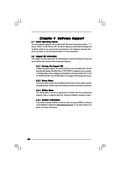
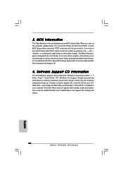
...-ROM drive. Chapter 4 Software Support 4.1 Install Operating System This motherboard supports various Microsoft® Windows® operating systems: 7 / 7 64-bit / VistaTM / VistaTM 64-bit / XP / XP 64-bit. If the Main Menu did not appear automatically, locate and double click on a specific item then follow the installation wizard to know more information. 4.2 Support CD Information The Support CD that came with the motherboard contains necessary drivers and useful utilities that the motherboard supports. Because motherboard settings...
...-ROM drive. Chapter 4 Software Support 4.1 Install Operating System This motherboard supports various Microsoft® Windows® operating systems: 7 / 7 64-bit / VistaTM / VistaTM 64-bit / XP / XP 64-bit. If the Main Menu did not appear automatically, locate and double click on a specific item then follow the installation wizard to know more information. 4.2 Support CD Information The Support CD that came with the motherboard contains necessary drivers and useful utilities that the motherboard supports. Because motherboard settings...
Quick Installation Guide
Page 2
... Header (PANEL1, Orange) 21 PCI Express x16 Slot (PCIE1) 10 Chassis Speaker Header 22 Front Panel Audio Header (SPEAKER 1, Purple) (HD_AUDIO1, Lime) 11 Secondary SATAII Connector (SATAII_2; Red) 2 ATX 12V Connector (ATX12V2) 13 USB 2.0 Header (USB4_5, Blue) 3 CPU Fan Connector (CPU_FAN1) 14 Chassis Fan Connector (CHA_FAN1) 4 ATX Power Connector (ATXPWR1) 15 Clear CMOS Jumper (CLRCMOS1) 5 2 x 240-pin DDR2 DIMM Slots 16 USB 2.0 Header (USB6_7, Blue) (Dual Channel: DDRII_1, DDRII_2; Red) 23 Print Port Header (LPT1, Purple) 2 ASRock G41M-VS2 Motherboard Motherboard Layout...
... Header (PANEL1, Orange) 21 PCI Express x16 Slot (PCIE1) 10 Chassis Speaker Header 22 Front Panel Audio Header (SPEAKER 1, Purple) (HD_AUDIO1, Lime) 11 Secondary SATAII Connector (SATAII_2; Red) 2 ATX 12V Connector (ATX12V2) 13 USB 2.0 Header (USB4_5, Blue) 3 CPU Fan Connector (CPU_FAN1) 14 Chassis Fan Connector (CHA_FAN1) 4 ATX Power Connector (ATXPWR1) 15 Clear CMOS Jumper (CLRCMOS1) 5 2 x 240-pin DDR2 DIMM Slots 16 USB 2.0 Header (USB6_7, Blue) (Dual Channel: DDRII_1, DDRII_2; Red) 23 Print Port Header (LPT1, Purple) 2 ASRock G41M-VS2 Motherboard Motherboard Layout...
Quick Installation Guide
Page 6
... Version) Unique Feature - SMBIOS 2.3.1 Support - Instant Boot - Boot Failure Guard (B.F.G.) Hardware - Microsoft® Windows® 7 / 7 64-bit / VistaTM / VistaTM 64-bit / XP / XP 64-bit compliant Certifications - CPU/Chassis FAN connector - 24 pin ATX power connector - 4 pin 12V power connector - CPU Temperature Sensing Monitor - CPU Fan Tachometer - Connector - 2 x SATAII 3.0 Gb/s connectors (No Support for RAID and "Hot Plug" functions) (see CAUTION 6) - 1 x ATA100 IDE connector (supports 2 x IDE devices) - 1 x Print port header - Supports Smart BIOS...
... Version) Unique Feature - SMBIOS 2.3.1 Support - Instant Boot - Boot Failure Guard (B.F.G.) Hardware - Microsoft® Windows® 7 / 7 64-bit / VistaTM / VistaTM 64-bit / XP / XP 64-bit compliant Certifications - CPU/Chassis FAN connector - 24 pin ATX power connector - 4 pin 12V power connector - CPU Temperature Sensing Monitor - CPU Fan Tachometer - Connector - 2 x SATAII 3.0 Gb/s connectors (No Support for RAID and "Hot Plug" functions) (see CAUTION 6) - 1 x ATA100 IDE connector (supports 2 x IDE devices) - 1 x Print port header - Supports Smart BIOS...
Quick Installation Guide
Page 7
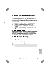
... devices to SATAII connector directly. 7. Before installing SATAII hard disk to read "Untied Overclocking Technology" on page 12 for details. 3. Power Management for the operation procedures of "User Manual" in the BIOS, applying Untied Overclocking Technology, or using the thirdparty overclocking tools. This motherboard supports Dual Channel Memory Technology. ASRock website: http://www.asrock.com 7 ASRock G41M-VS2 Motherboard English Please check Intel® website for system usage under Microsoft® Windows® VistaTM 64-bit / VistaTM / XP 64-bit...
... devices to SATAII connector directly. 7. Before installing SATAII hard disk to read "Untied Overclocking Technology" on page 12 for details. 3. Power Management for the operation procedures of "User Manual" in the BIOS, applying Untied Overclocking Technology, or using the thirdparty overclocking tools. This motherboard supports Dual Channel Memory Technology. ASRock website: http://www.asrock.com 7 ASRock G41M-VS2 Motherboard English Please check Intel® website for system usage under Microsoft® Windows® VistaTM 64-bit / VistaTM / XP 64-bit...
Quick Installation Guide
Page 8
... convenient BIOS update tool allows you to access ASRock Instant Flash. With this utility, you resume the system, please check if the CPU fan on the same motherboard. 12. The software name itself - Before you can save your friends! For EuP ready power supply selection, we recommend you can press key during the POST or press key to BIOS setup menu to update system BIOS without preparing an additional floppy diskette...
... convenient BIOS update tool allows you to access ASRock Instant Flash. With this utility, you resume the system, please check if the CPU fan on the same motherboard. 12. The software name itself - Before you can save your friends! For EuP ready power supply selection, we recommend you can press key during the POST or press key to BIOS setup menu to update system BIOS without preparing an additional floppy diskette...
Quick Installation Guide
Page 19
... during overclocking, but PCI / PCIE buses are in the fixed mode so that supports Serial ATA (SATA) / Serial ATAII (SATAII) hard disks. English 19 ASRock G41M-VS2 Motherboard Therefore, CPU FSB is untied during overclocking, FSB enjoys better margin due to the warning on the support CD driver page. STEP 3: Connect one end of your system can be auto-detected and listed on page 7 for internal storage devices. STEP 4: Connect the other end of BIOS setup to set...
... during overclocking, but PCI / PCIE buses are in the fixed mode so that supports Serial ATA (SATA) / Serial ATAII (SATAII) hard disks. English 19 ASRock G41M-VS2 Motherboard Therefore, CPU FSB is untied during overclocking, FSB enjoys better margin due to the warning on the support CD driver page. STEP 3: Connect one end of your system can be auto-detected and listed on page 7 for internal storage devices. STEP 4: Connect the other end of BIOS setup to set...
Quick Installation Guide
Page 20
... enter BIOS Setup utility; BIOS Information The Flash Memory on the system chassis. The Support CD that will display the Main Menu automatically if "AUTORUN" is designed to display the menus. 20 ASRock G41M-VS2 Motherboard English If you start up the computer, please press during the Power-On-Self-Test (POST) to select among the predetermined choices. For the detailed information about BIOS Setup, please refer to the User Manual (PDF file) contained in the Support...
... enter BIOS Setup utility; BIOS Information The Flash Memory on the system chassis. The Support CD that will display the Main Menu automatically if "AUTORUN" is designed to display the menus. 20 ASRock G41M-VS2 Motherboard English If you start up the computer, please press during the Power-On-Self-Test (POST) to select among the predetermined choices. For the detailed information about BIOS Setup, please refer to the User Manual (PDF file) contained in the Support...


