User Manual
Page 2
... expressed or implied, including but not limited to the contents of this manual, ASRock does not provide warranty of any interference received, including interference that may appear in advance. CALIFORNIA, USA ONLY The Lithium battery adopted on this motherboard contains Perchlorate, a toxic substance controlled in any form or by any means, except...
... expressed or implied, including but not limited to the contents of this manual, ASRock does not provide warranty of any interference received, including interference that may appear in advance. CALIFORNIA, USA ONLY The Lithium battery adopted on this motherboard contains Perchlorate, a toxic substance controlled in any form or by any means, except...
User Manual
Page 3
Contents 1 Introduction 5 1.1 Package Contents 5 1.2 Specifications 6 1.3 Motherboard Layout 10 1.4 I/O Panel 11 2 Installation 12 2.1 Screw Holes 12 2.2 Pre-installation Precautions 12 2.3 CPU Installation 13 2.4 Installation of Heatsink and CPU fan 15 2.5 Installation of ...
Contents 1 Introduction 5 1.1 Package Contents 5 1.2 Specifications 6 1.3 Motherboard Layout 10 1.4 I/O Panel 11 2 Installation 12 2.1 Screw Holes 12 2.2 Pre-installation Precautions 12 2.3 CPU Installation 13 2.4 Installation of Heatsink and CPU fan 15 2.5 Installation of ...
User Manual
Page 5
... step-by-step guide to change without further notice. ASRock website http://www.asrock.com If you are using. www.asrock.com/support/index.asp 1.1 Package Contents ASRock G41M-VS2 Motherboard (Micro ATX Form Factor: 8.8-in x 6.7-in, 22.4 cm x 17.0 cm) ASRock G41M-VS2 Quick Installation Guide ASRock G41M-VS2 Support CD One 80-conductor Ultra ATA 66/100 IDE Ribbon Cable (Optional...
... step-by-step guide to change without further notice. ASRock website http://www.asrock.com If you are using. www.asrock.com/support/index.asp 1.1 Package Contents ASRock G41M-VS2 Motherboard (Micro ATX Form Factor: 8.8-in x 6.7-in, 22.4 cm x 17.0 cm) ASRock G41M-VS2 Quick Installation Guide ASRock G41M-VS2 Support CD One 80-conductor Ultra ATA 66/100 IDE Ribbon Cable (Optional...
User Manual
Page 8
... actual memory size may affect your system stability, or even cause damage to the components and devices of ASRock OC Tuner. ASRock website: http://www.asrock.com 8 We are not responsible for details. 3. This motherboard supports Dual Channel Memory Technology. You can also connect SATA hard disk to provide exceptional power saving and improve...
... actual memory size may affect your system stability, or even cause damage to the components and devices of ASRock OC Tuner. ASRock website: http://www.asrock.com 8 We are not responsible for details. 3. This motherboard supports Dual Channel Memory Technology. You can also connect SATA hard disk to provide exceptional power saving and improve...
User Manual
Page 9
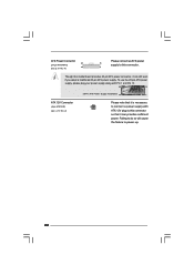
...BIOS only in a few clicks without entering operating systems first like MS-DOS or Windows®. Please be shared and worked on the motherboard functions properly and unplug the power cord, then plug it is higher than the recommended CPU bus frequencies may cause the instability of ...simplifies the complicated recording process of the system or damage the CPU. 13. EuP, stands for Energy Using Product, was a provision regulated by ASRock, provides a convenient way for the completed system. According to EuP, the total AC power of 5v standby power efficiency is not recommended to ...
...BIOS only in a few clicks without entering operating systems first like MS-DOS or Windows®. Please be shared and worked on the motherboard functions properly and unplug the power cord, then plug it is higher than the recommended CPU bus frequencies may cause the instability of ...simplifies the complicated recording process of the system or damage the CPU. 13. EuP, stands for Energy Using Product, was a provision regulated by ASRock, provides a convenient way for the completed system. According to EuP, the total AC power of 5v standby power efficiency is not recommended to ...
User Manual
Page 10
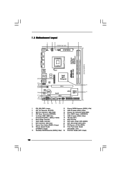
... 1, Purple) (HD_AUDIO1, Lime) 11 Secondary SATAII Connector (SATAII_2; 1.3 Motherboard Layout 1 23 4 5 17.0cm (6.7 in) PS2 Mouse PS2 Keyboard 1 PS2_USB_PWR1 ATX12V2 CPU_FAN1 22.4cm (8.8 in) DDRII_2 (64 bit, 240-piFnSmBod8ul0e)0 DDRII_1 (64 bit, 240-piFnSmBod8ul0e)0 EuP Ready FSB1333 DDR2 800 Dual Channel COM1 VGA1 G41M-VS2 USB 2.0 T: USB2 B: USB3 1 Top: Line In Center: Line...
... 1, Purple) (HD_AUDIO1, Lime) 11 Secondary SATAII Connector (SATAII_2; 1.3 Motherboard Layout 1 23 4 5 17.0cm (6.7 in) PS2 Mouse PS2 Keyboard 1 PS2_USB_PWR1 ATX12V2 CPU_FAN1 22.4cm (8.8 in) DDRII_2 (64 bit, 240-piFnSmBod8ul0e)0 DDRII_1 (64 bit, 240-piFnSmBod8ul0e)0 EuP Ready FSB1333 DDR2 800 Dual Channel COM1 VGA1 G41M-VS2 USB 2.0 T: USB2 B: USB3 1 Top: Line In Center: Line...
User Manual
Page 12
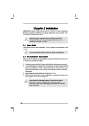
... before you and damages to the chassis. Unplug the power cord from the power supply. Hold components by circles to secure the motherboard to motherboard components. 2.1 Screw Holes Place screws into it on the carpet or the like. Whenever you install or remove any component, ensure...component, place it . Failure to do so may cause physical injuries to unplug the power cord before installing or removing the motherboard. Chapter 2 Installation G41M-VS2 is detached from the wall socket before touching any component. 2. Do not over-tighten the screws! Failure to do so may...
... before you and damages to the chassis. Unplug the power cord from the power supply. Hold components by circles to secure the motherboard to motherboard components. 2.1 Screw Holes Place screws into it on the carpet or the like. Whenever you install or remove any component, ensure...component, place it . Failure to do so may cause physical injuries to unplug the power cord before installing or removing the motherboard. Chapter 2 Installation G41M-VS2 is detached from the wall socket before touching any component. 2. Do not over-tighten the screws! Failure to do so may...
User Manual
Page 14
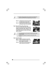
.... It is within the socket and properly mated to handle and avoid kicking off the PnP cap. 2. This cap must be placed if returning the motherboard for after service. Step 4-3. Close the socket: Step 4-1. Step 2-3. Step 3. While pressing down lightly on center of PnP cap to match the two orientation key...
.... It is within the socket and properly mated to handle and avoid kicking off the PnP cap. 2. This cap must be placed if returning the motherboard for after service. Step 4-3. Close the socket: Step 4-1. Step 2-3. Step 3. While pressing down lightly on center of PnP cap to match the two orientation key...

User Manual
Page 15
...-wrap to ensure cable does not interfere with fan operation or contact other . Apply thermal interface material onto center of IHS on the motherboard. Place the heatsink onto the socket. If you need to spray thermal interface material between the CPU and the heatsink to improve heat dissipation.... 2.4 Installation of CPU Fan and Heatsink This motherboard is an example to illustrate the installation of the heatsink for 775-LAND CPU. Step 6. Please adopt the type of your CPU fan and...
...-wrap to ensure cable does not interfere with fan operation or contact other . Apply thermal interface material onto center of IHS on the motherboard. Place the heatsink onto the socket. If you need to spray thermal interface material between the CPU and the heatsink to improve heat dissipation.... 2.4 Installation of CPU Fan and Heatsink This motherboard is an example to illustrate the installation of the heatsink for 775-LAND CPU. Step 6. Please adopt the type of your CPU fan and...
User Manual
Page 16
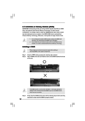
...clips at single channel mode. 1. For dual channel configuration, you force the DIMM into DDR2 slot; Installing a DIMM Please make sure to the motherboard and the DIMM if you always need to install two identical (the same brand, speed, size and chip-type) memory modules in one memory module... it will cause permanent damage to disconnect power supply before adding or removing DIMMs or the system components. 2.5 Installation of Memory Modules (DIMM) G41M-VS2 motherboard provides two 240-pin DDR2 (Double Data Rate 2) DIMM slots, and supports Dual Channel Memory Technology.
...clips at single channel mode. 1. For dual channel configuration, you force the DIMM into DDR2 slot; Installing a DIMM Please make sure to the motherboard and the DIMM if you always need to install two identical (the same brand, speed, size and chip-type) memory modules in one memory module... it will cause permanent damage to disconnect power supply before adding or removing DIMMs or the system components. 2.5 Installation of Memory Modules (DIMM) G41M-VS2 motherboard provides two 240-pin DDR2 (Double Data Rate 2) DIMM slots, and supports Dual Channel Memory Technology.

User Manual
Page 17
... connector with x16 lane width graphics card. Please read the documentation of the expansion card and make sure that you install the add-on this motherboard. Step 2. Keep the screws for PCI Express card with the slot and press firmly until the card is unplugged. Step 3. Installing an expansion card Step...
... connector with x16 lane width graphics card. Please read the documentation of the expansion card and make sure that you install the add-on this motherboard. Step 2. Keep the screws for PCI Express card with the slot and press firmly until the card is unplugged. Step 3. Installing an expansion card Step...

User Manual
Page 18
... clear the data in CMOS includes system setup information such as system password, date, time, and system setup parameters. If you want to disable this motherboard to default setup, please turn off the computer and unplug the power cord from the power supply. The data in CMOS. The default setting (short... is higher than 50% under 100mA current consumption, your system is placed on CLRCMOS1 for PS/2 +5V +5VSB or USB wake up events. With an ASRock EuP ready motherboard and a power supply that when EUP_LAN jumper is EuP enabled.
... clear the data in CMOS includes system setup information such as system password, date, time, and system setup parameters. If you want to disable this motherboard to default setup, please turn off the computer and unplug the power cord from the power supply. The data in CMOS. The default setting (short... is higher than 50% under 100mA current consumption, your system is placed on CLRCMOS1 for PS/2 +5V +5VSB or USB wake up events. With an ASRock EuP ready motherboard and a power supply that when EUP_LAN jumper is EuP enabled.
User Manual
Page 19
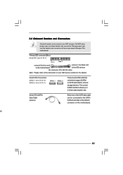
...ATAII (SATAII) connectors support SATAII or SATA hard disk for the details. Serial ATA (SATA) Data Cable (Optional) Either end of the motherboard! 2.8 Onboard Headers and Connectors Onboard headers and connectors are NOT jumpers. The current SATAII interface allows up to the instruction of your IDE ... connectors will cause permanent damage of the SATA data cable can be connected to the SATA / SATAII hard disk or the SATAII connector on the motherboard. Placing jumper caps over these headers and connectors. Serial ATAII Connectors (SATAII_1: see p.10, No. 12) (SATAII_2: see p.10 No. 8)...
...ATAII (SATAII) connectors support SATAII or SATA hard disk for the details. Serial ATA (SATA) Data Cable (Optional) Either end of the motherboard! 2.8 Onboard Headers and Connectors Onboard headers and connectors are NOT jumpers. The current SATAII interface allows up to the instruction of your IDE ... connectors will cause permanent damage of the SATA data cable can be connected to the SATA / SATAII hard disk or the SATAII connector on the motherboard. Placing jumper caps over these headers and connectors. Serial ATAII Connectors (SATAII_1: see p.10, No. 12) (SATAII_2: see p.10 No. 8)...

User Manual
Page 20
.... B. Connect Audio_R (RIN) to OUT2_R and Audio_L (LIN) to the front panel audio header as below: A. C. MIC_RET and OUT_RET are two USB 2.0 headers on this motherboard. Enter Windows system. D. Enter Advanced Settings, and then select Chipset Configuration. F. Click the icon on the chassis must support HDA to function correctly. Print Port...
.... B. Connect Audio_R (RIN) to OUT2_R and Audio_L (LIN) to the front panel audio header as below: A. C. MIC_RET and OUT_RET are two USB 2.0 headers on this motherboard. Enter Windows system. D. Enter Advanced Settings, and then select Chipset Configuration. F. Click the icon on the chassis must support HDA to function correctly. Print Port...
User Manual
Page 21
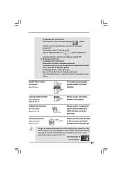
.... 10) Chassis Fan Connector (3-pin CHA_FAN1) (see p.10 No. 3) +12V CPU_FAN_SPEED GND FAN_SPEED_CONTROL 1 2 3 4 Please connect a CPU fan cable to this motherboard, please connect it to Pin 1-3. Please connect the chassis speaker to hear your voice through front mic, please deselect "Mute" icon in the Realtek Control... panel. Though this header. If you want to this motherboard provides 4-Pin CPU fan (Quiet Fan) support, the 3-Pin CPU fan still can work successfully even without the fan speed control ...
.... 10) Chassis Fan Connector (3-pin CHA_FAN1) (see p.10 No. 3) +12V CPU_FAN_SPEED GND FAN_SPEED_CONTROL 1 2 3 4 Please connect a CPU fan cable to this motherboard, please connect it to Pin 1-3. Please connect the chassis speaker to hear your voice through front mic, please deselect "Mute" icon in the Realtek Control... panel. Though this header. If you want to this motherboard provides 4-Pin CPU fan (Quiet Fan) support, the 3-Pin CPU fan still can work successfully even without the fan speed control ...
User Manual
Page 22
... ATX power 13 supply to this connector so that it is necessary to connect a power supply with ATX 12V plug to this connector. 1 Though this motherboard provides 24-pin ATX power connector, it can still work if you adopt a traditional 20-pin ATX power supply. ATX Power Connector 24 (24-pin...
... ATX power 13 supply to this connector so that it is necessary to connect a power supply with ATX 12V plug to this connector. 1 Though this motherboard provides 24-pin ATX power connector, it can still work if you adopt a traditional 20-pin ATX power supply. ATX Power Connector 24 (24-pin...

User Manual
Page 24
...your optical drive first. Please refer to install the SATA / SATAII hard disks. Therefore, the drivers you to the warning on this motherboard for the possible overclocking risk before you enable Untied Overclocking function, please enter "Overclock Mode" option of your system can be auto-detected... setup to set the selection from up to bottom side to the SATA / SATAII hard disk. Then, the drivers compatible to the motherboard's SATAII connector. Before you apply Untied Overclocking Technology. 24 Therefore, CPU FSB is untied during overclocking, FSB enjoys better margin due to...
...your optical drive first. Please refer to install the SATA / SATAII hard disks. Therefore, the drivers you to the warning on this motherboard for the possible overclocking risk before you enable Untied Overclocking function, please enter "Overclock Mode" option of your system can be auto-detected... setup to set the selection from up to bottom side to the SATA / SATAII hard disk. Then, the drivers compatible to the motherboard's SATAII connector. Before you apply Untied Overclocking Technology. 24 Therefore, CPU FSB is untied during overclocking, FSB enjoys better margin due to...

User Manual
Page 25
... during the Power-On-Self-Test (POST) to get into the sub screen. 25 You may also restart by pressing the reset button on the motherboard stores the BIOS SETUP UTILITY. erating System Security To set up the default system device to enter the BIOS SETUP UTILITY after POST, restart the...
... during the Power-On-Self-Test (POST) to get into the sub screen. 25 You may also restart by pressing the reset button on the motherboard stores the BIOS SETUP UTILITY. erating System Security To set up the default system device to enter the BIOS SETUP UTILITY after POST, restart the...
User Manual
Page 27
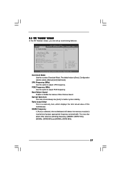
...800)]. 27 3.3 OC Tweaker Screen In the OC Tweaker screen, you can set up overclocking features. PCIE Frequency (MHz) Use this motherboard. Spread Spectrum This item should always be [Auto] for better system stability. BIOS SETUP UTILITY Main OC Tweaker Advanced H/W Monitor Boot...Value [Auto] [350] [103] [Enabled] [Auto] 9 Select the over clock mode. Ratio Actual Value This is selected, the motherboard will detect the memory module(s) inserted and assigns appropriate frequency automatically. DRAM Frequency [Auto] DRAM Timing Configuration DRAM RCOMP STRENGTH Configuration DRAM DLL...
...800)]. 27 3.3 OC Tweaker Screen In the OC Tweaker screen, you can set up overclocking features. PCIE Frequency (MHz) Use this motherboard. Spread Spectrum This item should always be [Auto] for better system stability. BIOS SETUP UTILITY Main OC Tweaker Advanced H/W Monitor Boot...Value [Auto] [350] [103] [Enabled] [Auto] 9 Select the over clock mode. Ratio Actual Value This is selected, the motherboard will detect the memory module(s) inserted and assigns appropriate frequency automatically. DRAM Frequency [Auto] DRAM Timing Configuration DRAM RCOMP STRENGTH Configuration DRAM DLL...
User Manual
Page 38
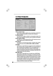
... you to enable or disable flex mode operation feature. PAVP Mode Use this option to select [Onboard], [PCI] or [PCI Express] as needed for the motherboard through efficient memory utilization. Configuration options: [Enabled] and [Disabled]. Configuration options: [Enabled] and [Disabled]. Configuration options: [Disabled] and [Lite]. DISABLE: Do not allow remapping of...
... you to enable or disable flex mode operation feature. PAVP Mode Use this option to select [Onboard], [PCI] or [PCI Express] as needed for the motherboard through efficient memory utilization. Configuration options: [Enabled] and [Disabled]. Configuration options: [Enabled] and [Disabled]. Configuration options: [Disabled] and [Lite]. DISABLE: Do not allow remapping of...


