User Manual
Page 2
... responsibility for informational use only and subject to change without intent to infringe. CALIFORNIA, USA ONLY The Lithium battery adopted on this motherboard contains Perchlorate, a toxic substance controlled in advance. Products and corporate names appearing in this manual may or may not be registered trademarks..., and are furnished for any errors or omissions that may cause undesired operation. With respect to the contents of this manual, ASRock does not provide warranty of any kind, either expressed or implied, including but not limited to the implied warranties or conditions of...
... responsibility for informational use only and subject to change without intent to infringe. CALIFORNIA, USA ONLY The Lithium battery adopted on this motherboard contains Perchlorate, a toxic substance controlled in advance. Products and corporate names appearing in this manual may or may not be registered trademarks..., and are furnished for any errors or omissions that may cause undesired operation. With respect to the contents of this manual, ASRock does not provide warranty of any kind, either expressed or implied, including but not limited to the implied warranties or conditions of...
User Manual
Page 3
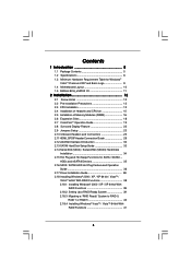
Contents 1 Introduction 5 1.1 Package Contents 5 1.2 Specifications 6 1.3 Minimum Hardware Requirement Table for Windows® VistaTM Premium 2007 and Basic Logo 9 1.4 Motherboard Layout 10 1.5 ASRock 8CH_eSATAII I/O 11 2 Installation 12 2.1 Screw Holes 12 2.2 Pre-installation Precautions 12 2.3 CPU Installation 13 2.4 Installation of Heatsink and CPU fan 15 2.5 Installation of Memory Modules (...
Contents 1 Introduction 5 1.1 Package Contents 5 1.2 Specifications 6 1.3 Minimum Hardware Requirement Table for Windows® VistaTM Premium 2007 and Basic Logo 9 1.4 Motherboard Layout 10 1.5 ASRock 8CH_eSATAII I/O 11 2 Installation 12 2.1 Screw Holes 12 2.2 Pre-installation Precautions 12 2.3 CPU Installation 13 2.4 Installation of Heatsink and CPU fan 15 2.5 Installation of Memory Modules (...
User Manual
Page 5
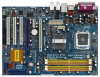
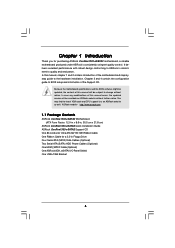
...3.5-in , 30.5 cm x 21.8 cm) ASRock ConRoe1333-eSATA2 Quick Installation Guide ASRock ConRoe1333-eSATA2 Support CD One 80-conductor Ultra ATA 66/100 IDE Ribbon Cable One Ribbon Cable for purchasing ASRock ConRoe1333-eSATA2 motherboard, a reliable motherboard produced under ASRock's consistently stringent quality control. In this manual, chapter.... You may find the latest VGA cards and CPU support lists on ASRock website without notice. ASRock website http://www.asrock.com 1.1 Package Contents ASRock ConRoe1333-eSATA2 Motherboard (ATX Form Factor: 12.0-in x 8.6-in Floppy Drive Four Serial ...
...3.5-in , 30.5 cm x 21.8 cm) ASRock ConRoe1333-eSATA2 Quick Installation Guide ASRock ConRoe1333-eSATA2 Support CD One 80-conductor Ultra ATA 66/100 IDE Ribbon Cable One Ribbon Cable for purchasing ASRock ConRoe1333-eSATA2 motherboard, a reliable motherboard produced under ASRock's consistently stringent quality control. In this manual, chapter.... You may find the latest VGA cards and CPU support lists on ASRock website without notice. ASRock website http://www.asrock.com 1.1 Package Contents ASRock ConRoe1333-eSATA2 Motherboard (ATX Form Factor: 12.0-in x 8.6-in Floppy Drive Four Serial ...
User Manual
Page 8
... to the components and devices of memory modules on page 11 for possible damage caused by overclocking. For audio output, this motherboard, it back again. About the setting of the system or damage the CPU. 8. To improve heat dissipation, remember to read... is detected, the system will operate in the BIOS, applying Untied Overclocking Technology, or using the thirdparty overclocking tools. This motherboard supports Dual Channel Memory Technology. Frequencies other than 4GB for the reservation for proper installation. 5. Before you install the PC ...
... to the components and devices of memory modules on page 11 for possible damage caused by overclocking. For audio output, this motherboard, it back again. About the setting of the system or damage the CPU. 8. To improve heat dissipation, remember to read... is detected, the system will operate in the BIOS, applying Untied Overclocking Technology, or using the thirdparty overclocking tools. This motherboard supports Dual Channel Memory Technology. Frequencies other than 4GB for the reservation for proper installation. 5. Before you install the PC ...
User Manual
Page 9
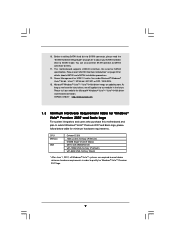
..., we will update it to SATAII mode. ASRock website http://www.asrock.com 1.3 Minimum Hardware Requirement Table for Windows® VistaTM Premium 2007 and Basic Logo For system integrators and users who purchase this motherboard and plan to submit Windows® VistaTM Premium... Premium 2007 logo. 9 Before installing SATAII hard disk to SATAII connector, please read "eSATAII Interface Introduction" on updating now. This motherboard supports eSATAII interface, the external SATAII specification. CPU Memory VGA Celeron D 326 1GB system memory (Premium) 512MB Single Channel (Basic)...
..., we will update it to SATAII mode. ASRock website http://www.asrock.com 1.3 Minimum Hardware Requirement Table for Windows® VistaTM Premium 2007 and Basic Logo For system integrators and users who purchase this motherboard and plan to submit Windows® VistaTM Premium... Premium 2007 logo. 9 Before installing SATAII hard disk to SATAII connector, please read "eSATAII Interface Introduction" on updating now. This motherboard supports eSATAII interface, the external SATAII specification. CPU Memory VGA Celeron D 326 1GB system memory (Premium) 512MB Single Channel (Basic)...
User Manual
Page 12
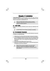
... the power is switched off or the power cord is an ATX form factor (12.0" x 8.6", 30.5 x 21.8 cm) motherboard. Whenever you install motherboard components or change any motherboard settings. 1. Before you handle components. 3. Chapter 2 Installation ConRoe1333-eSATA2 is detached from the wall socket before touching any component. 2. Also remember to unplug the power cord before...
... the power is switched off or the power cord is an ATX form factor (12.0" x 8.6", 30.5 x 21.8 cm) motherboard. Whenever you install motherboard components or change any motherboard settings. 1. Before you handle components. 3. Chapter 2 Installation ConRoe1333-eSATA2 is detached from the wall socket before touching any component. 2. Also remember to unplug the power cord before...
User Manual
Page 14
... of the CPU with load plate tab under retention tab of PnP cap to assist in removal. 1. This cap must be placed if returning the motherboard for after service.
... of the CPU with load plate tab under retention tab of PnP cap to assist in removal. 1. This cap must be placed if returning the motherboard for after service.
User Manual
Page 15
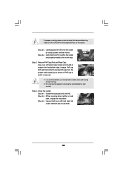
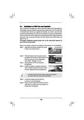
... CPU fan to the CPU_FAN connector (CPU_FAN1, see page 10, No. 6). Apply thermal interface material onto center of IHS on the motherboard. Ensure fan cables are securely fastened and in good contact with fan operation or contact other . Step 6. Secure excess cable with tie... between the CPU and the heatsink to the CPU fan connector on the motherboard (CPU_FAN1, see page 10, No. 6). Before you installed the heatsink, you press down on the motherboard. Step 1. Step 4. Repeat with the motherboard throughholes. Connect fan header with thumb to install and lock. 2.4 Installation...
... CPU fan to the CPU_FAN connector (CPU_FAN1, see page 10, No. 6). Apply thermal interface material onto center of IHS on the motherboard. Ensure fan cables are securely fastened and in good contact with fan operation or contact other . Step 6. Secure excess cable with tie... between the CPU and the heatsink to the CPU fan connector on the motherboard (CPU_FAN1, see page 10, No. 6). Before you installed the heatsink, you press down on the motherboard. Step 1. Step 4. Repeat with the motherboard throughholes. Connect fan header with thumb to install and lock. 2.4 Installation...
User Manual
Page 16
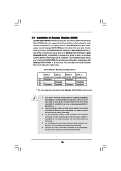
... 3. Orange slots; Populated (3)* Populated Populated Populated Populated * For the configuration (3), please install identical DDRII DIMMs in the DDRII DIMM slots on this motherboard and DIMM may refer to activate the Dual Channel Memory Technology . 4. 2.5 Installation of yellow slots (DDRII_1 and DDRII_3), or in Dual Channel A... and reliability, it is recommended to install identical DDRII DIMM pair in the set of Memory Modules (DIMM) ConRoe1333-eSATA2 motherboard provides four 240-pin DDRII (Double Data Rate II) DIMM slots, and supports Dual Channel Memory Technology.
... 3. Orange slots; Populated (3)* Populated Populated Populated Populated * For the configuration (3), please install identical DDRII DIMMs in the DDRII DIMM slots on this motherboard and DIMM may refer to activate the Dual Channel Memory Technology . 4. 2.5 Installation of yellow slots (DDRII_1 and DDRII_3), or in Dual Channel A... and reliability, it is recommended to install identical DDRII DIMM pair in the set of Memory Modules (DIMM) ConRoe1333-eSATA2 motherboard provides four 240-pin DDRII (Double Data Rate II) DIMM slots, and supports Dual Channel Memory Technology.
User Manual
Page 17
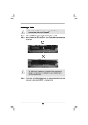
Installing a DIMM Please make sure to the motherboard and the DIMM if you force the DIMM into the slot until the retaining clips at incorrect orientation. Firmly insert the DIMM into the slot ...
Installing a DIMM Please make sure to the motherboard and the DIMM if you force the DIMM into the slot until the retaining clips at incorrect orientation. Firmly insert the DIMM into the slot ...
User Manual
Page 18
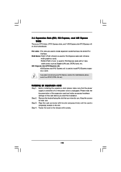
... facing the slot that the power supply is switched off or the power cord is used to install only one PCI Express card on this motherboard. Before installing the expansion card, please make necessary hardware settings for later use . PCI slots: PCI slots are 3 PCI slots, 2 PCI Express slots, and 1 AGI...
... facing the slot that the power supply is switched off or the power cord is used to install only one PCI Express card on this motherboard. Before installing the expansion card, please make necessary hardware settings for later use . PCI slots: PCI slots are 3 PCI slots, 2 PCI Express slots, and 1 AGI...
User Manual
Page 19
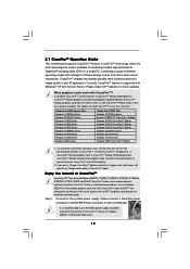
...If a customer incorrectly configures their system they are software enabled. All three CrossFireTM components, a CrossFireTM Ready graphics card, a CrossFireTM Ready motherboard and a CrossFireTM Edition co-processor graphics card, must be installed correctly to cards from the same series, or two CrossFireTM Ready cards... if they will release in any of its partners. Step 1. Connect to SLI/XFIRE Power connector on this motherboard. Please connect a hard disk power connector to the system power supply. What graphics cards work with Service Pack 2. A complete ...
...If a customer incorrectly configures their system they are software enabled. All three CrossFireTM components, a CrossFireTM Ready graphics card, a CrossFireTM Ready motherboard and a CrossFireTM Edition co-processor graphics card, must be installed correctly to cards from the same series, or two CrossFireTM Ready cards... if they will release in any of its partners. Step 1. Connect to SLI/XFIRE Power connector on this motherboard. Please connect a hard disk power connector to the system power supply. What graphics cards work with Service Pack 2. A complete ...
User Manual
Page 20
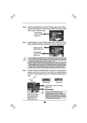
... 2. You are allowed to install two CrossFireTM Edition graphics cards to both slots, or you install two standard Radeon (CrossFireTM Ready) graphics cards to this motherboard, please skip this step.) DVI-DMS cable Connect the DVI-DMS cable to support CrossFireTM.
... 2. You are allowed to install two CrossFireTM Edition graphics cards to both slots, or you install two standard Radeon (CrossFireTM Ready) graphics cards to this motherboard, please skip this step.) DVI-DMS cable Connect the DVI-DMS cable to support CrossFireTM.
User Manual
Page 21
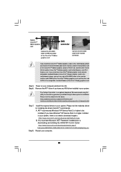
...higher installed in your system, there is an optional download. Remove the ATITM driver if you install two CrossFireTM Edition graphics cards to this motherboard, please connect one of the CrossFireTM Edition graphics cards to PCIE1 slot, and the other end to DVI of the compatible standard Radeon (CrossFireTM... higher to be installed (If you install one CrossFireTM Edition graphics card and one compatible standard Radeon (CrossFireTM Ready) graphics card to this motherboard, please connect one end of DVI-DMS cable to the monitor, another end to DMS of one end of DVI-DMS cable to the...
...higher installed in your system, there is an optional download. Remove the ATITM driver if you install two CrossFireTM Edition graphics cards to this motherboard, please connect one of the CrossFireTM Edition graphics cards to PCIE1 slot, and the other end to DVI of the compatible standard Radeon (CrossFireTM... higher to be installed (If you install one CrossFireTM Edition graphics card and one compatible standard Radeon (CrossFireTM Ready) graphics card to this motherboard, please connect one end of DVI-DMS cable to the monitor, another end to DMS of one end of DVI-DMS cable to the...
User Manual
Page 22
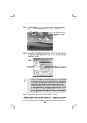
Click "CrossFireTM", and then set the option "Enable CrossFireTM" to this motherboard but not two Radeon CrossFireTM Edition graphics cards, please as well follow the above steps. Step 11. Step 9. However, although you are able to infringe. ...
Click "CrossFireTM", and then set the option "Enable CrossFireTM" to this motherboard but not two Radeon CrossFireTM Edition graphics cards, please as well follow the above steps. Step 11. Step 9. However, although you are able to infringe. ...
User Manual
Page 23
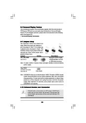
... PS2_USB_PWR1 1_2 (see p.10 No. 10) 2-pin jumper Note: CLRCMOS1 allows you can easily enjoy the benefits of the motherboard! 23 To clear and reset the system parameters to clear the data in CMOS includes system setup information such as system password... seconds. 2.10 Onboard Headers and Connectors Onboard headers and connectors are setup. Placing jumper caps over these 2 pins. 2.8 Surround Display Feature This motherboard supports Surround Display upgrade. With the external add-on these headers and connectors. The illustration shows a 3-pin jumper whose pin1 and pin2 are ...
... PS2_USB_PWR1 1_2 (see p.10 No. 10) 2-pin jumper Note: CLRCMOS1 allows you can easily enjoy the benefits of the motherboard! 23 To clear and reset the system parameters to clear the data in CMOS includes system setup information such as system password... seconds. 2.10 Onboard Headers and Connectors Onboard headers and connectors are setup. Placing jumper caps over these 2 pins. 2.8 Surround Display Feature This motherboard supports Surround Display upgrade. With the external add-on these headers and connectors. The illustration shows a 3-pin jumper whose pin1 and pin2 are ...
User Manual
Page 24
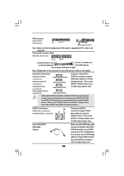
Please read "eSATAII Interface Introduction" on the motherboard. eSATA II Connectors (eSATAII_TOP: see p.10, No. 37) (eSATAII_BOTTOM: see p.10, No. 36) eSATAII_TOP eSATAII_BOTTOM These two eSATA II connectors support SATA data cables for ... installation procedures. Primary IDE connector (Blue) (39-pin IDE1, see p.10 No. 16) PIN1 IDE1 connect the blue end connect the black end to the motherboard to the IDE devices 80-conductor ATA 66/100 cable Note: Please refer to the instruction of your IDE device vendor for internal storage devices...
Please read "eSATAII Interface Introduction" on the motherboard. eSATA II Connectors (eSATAII_TOP: see p.10, No. 37) (eSATAII_BOTTOM: see p.10, No. 36) eSATAII_TOP eSATAII_BOTTOM These two eSATA II connectors support SATA data cables for ... installation procedures. Primary IDE connector (Blue) (39-pin IDE1, see p.10 No. 16) PIN1 IDE1 connect the blue end connect the black end to the motherboard to the IDE devices 80-conductor ATA 66/100 cable Note: Please refer to the instruction of your IDE device vendor for internal storage devices...
User Manual
Page 25
This connector allows you to the power connector on this motherboard. Each USB 2.0 header can support two USB 2.0 ports. (9-pin USB45) (see p.10 No. 23) (9-pin USB23) (see p.10 No. 24) USB_PWR P-5 P+5 GND DUMMY 1 GND P+4 P-4 USB_PWR ...
This connector allows you to the power connector on this motherboard. Each USB 2.0 header can support two USB 2.0 ports. (9-pin USB45) (see p.10 No. 23) (9-pin USB23) (see p.10 No. 24) USB_PWR P-5 P+5 GND DUMMY 1 GND P+4 P-4 USB_PWR ...
User Manual
Page 27
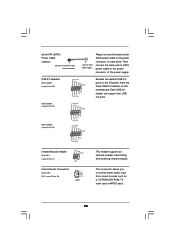
... to this connector. SLI/XFIRE Power Connector (4-pin SLI/XFIRE_POWER1) (see p.10 No. 2) Please connect an ATX 12V power supply to this motherboard, including one front panel IEEE 1394 header (FRONT_1394) and one IEEE 1394 port. 27 Each IEEE 1394 header can work successfully even without the ...fan speed control function. Though this motherboard at the same time. Game Port Header (15-pin GAME1) (see p.10 No. 27) IEEE 1394 Headers (9-pin FRONT_1394) (see p.10 No. ...
... to this connector. SLI/XFIRE Power Connector (4-pin SLI/XFIRE_POWER1) (see p.10 No. 2) Please connect an ATX 12V power supply to this motherboard, including one front panel IEEE 1394 header (FRONT_1394) and one IEEE 1394 port. 27 Each IEEE 1394 header can work successfully even without the ...fan speed control function. Though this motherboard at the same time. Game Port Header (15-pin GAME1) (see p.10 No. 27) IEEE 1394 Headers (9-pin FRONT_1394) (see p.10 No. ...
User Manual
Page 28
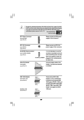
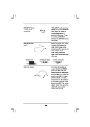
... blue connector on the cable of this USB+1394 bracket to the USB 2.0 header (USB23, USB45, or USB67), and connect the red connector on the motherboard. HDMI_SPDIF Header (3-pin HDMI_SPDIF1) (see p.10 No. 30) 1 GND SPDIFOUT +5V HDMI_SPDIF Cable (Optional) C B A HDMI_SPDIF header, providing SPDIF audio output to HDMI VGA card, allows...
... blue connector on the cable of this USB+1394 bracket to the USB 2.0 header (USB23, USB45, or USB67), and connect the red connector on the motherboard. HDMI_SPDIF Header (3-pin HDMI_SPDIF1) (see p.10 No. 30) 1 GND SPDIFOUT +5V HDMI_SPDIF Cable (Optional) C B A HDMI_SPDIF header, providing SPDIF audio output to HDMI VGA card, allows...

