User Manual
Page 2
...purchaser for identification or explanation and to the owners' benefit, without intent to change without written consent of ASRock Inc. ASRock assumes no event shall ASRock, its directors, officers, employees, or agents be liable for any indirect, special, incidental, or consequential damages...form or by any means, except duplication of documentation by the California Legislature. Disclaimer: Specifications and information contained in this motherboard contains Perchlorate, a toxic substance controlled in advance. CALIFORNIA, USA ONLY The Lithium battery adopted on this manual are ...
...purchaser for identification or explanation and to the owners' benefit, without intent to change without written consent of ASRock Inc. ASRock assumes no event shall ASRock, its directors, officers, employees, or agents be liable for any indirect, special, incidental, or consequential damages...form or by any means, except duplication of documentation by the California Legislature. Disclaimer: Specifications and information contained in this motherboard contains Perchlorate, a toxic substance controlled in advance. CALIFORNIA, USA ONLY The Lithium battery adopted on this manual are ...
User Manual
Page 3
Contents 1 Introduction 5 1.1 Package Contents 5 1.2 Specifications 6 1.3 Minimum Hardware Requirement Table for Windows® VistaTM Premium 2007 and Basic Logo 9 1.4 Motherboard Layout 10 1.5 ASRock 8CH_eSATAII I/O 11 2 Installation 12 2.1 Screw Holes 12 2.2 Pre-installation Precautions 12 2.3 CPU Installation 13 2.4 Installation of Heatsink and CPU fan 15 2.5 Installation of Memory Modules (...
Contents 1 Introduction 5 1.1 Package Contents 5 1.2 Specifications 6 1.3 Minimum Hardware Requirement Table for Windows® VistaTM Premium 2007 and Basic Logo 9 1.4 Motherboard Layout 10 1.5 ASRock 8CH_eSATAII I/O 11 2 Installation 12 2.1 Screw Holes 12 2.2 Pre-installation Precautions 12 2.3 CPU Installation 13 2.4 Installation of Heatsink and CPU fan 15 2.5 Installation of Memory Modules (...
User Manual
Page 5
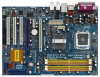
... without notice. In case any modifications of this manual occur, the updated version will be available on ASRock website as well. ASRock website http://www.asrock.com 1.1 Package Contents ASRock ConRoe1333-eSATA2 Motherboard (ATX Form Factor: 12.0-in x 8.6-in Floppy Drive Four Serial ATA (SATA) Data Cables (Optional) Two Serial ATA (SATA) HDD Power Cables (Optional) One...
... without notice. In case any modifications of this manual occur, the updated version will be available on ASRock website as well. ASRock website http://www.asrock.com 1.1 Package Contents ASRock ConRoe1333-eSATA2 Motherboard (ATX Form Factor: 12.0-in x 8.6-in Floppy Drive Four Serial ATA (SATA) Data Cables (Optional) Two Serial ATA (SATA) HDD Power Cables (Optional) One...
User Manual
Page 8
...the heatsink when you implement Dual Channel Memory Technology, make sure to 115MHz. 2. Please check the table on this motherboard, it will operate in the BIOS, applying Untied Overclocking Technology, or using the thirdparty overclocking tools. It should ... 8-channel modes. Overclocking may cause the instability of the system or damage the CPU. 8. This motherboard supports Untied Overclocking Technology. For audio output, this motherboard supports both stereo and mono modes. sponding memory support frequency. Although this situation, PCIE frequency will automatically...
...the heatsink when you implement Dual Channel Memory Technology, make sure to 115MHz. 2. Please check the table on this motherboard, it will operate in the BIOS, applying Untied Overclocking Technology, or using the thirdparty overclocking tools. It should ... 8-channel modes. Overclocking may cause the instability of the system or damage the CPU. 8. This motherboard supports Untied Overclocking Technology. For audio output, this motherboard supports both stereo and mono modes. sponding memory support frequency. Although this situation, PCIE frequency will automatically...
User Manual
Page 9
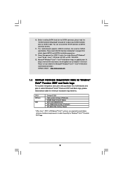
...minimum hardware requirements in the future. You can also connect SATA hard disk to our website in order to SATAII mode. This motherboard supports eSATAII interface, the external SATAII specification. Please read the "SATAII Hard Disk Setup Guide" on page 33 to adjust ...will update it to SATAII connector directly. 11. 10. ASRock website http://www.asrock.com 1.3 Minimum Hardware Requirement Table for Windows® VistaTM Premium 2007 and Basic Logo For system integrators and users who purchase this motherboard and plan to SATAII connector, please read "eSATAII Interface ...
...minimum hardware requirements in the future. You can also connect SATA hard disk to our website in order to SATAII mode. This motherboard supports eSATAII interface, the external SATAII specification. Please read the "SATAII Hard Disk Setup Guide" on page 33 to adjust ...will update it to SATAII connector directly. 11. 10. ASRock website http://www.asrock.com 1.3 Minimum Hardware Requirement Table for Windows® VistaTM Premium 2007 and Basic Logo For system integrators and users who purchase this motherboard and plan to SATAII connector, please read "eSATAII Interface ...
User Manual
Page 12
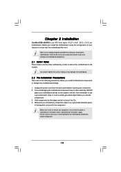
...carpet or the like. Do not over-tighten the screws! Before you handle components. 3. Also remember to ensure that the motherboard fits into the holes indicated by the edges and do so may cause severe damage to static electricity, NEVER place your ...from the wall socket before you install the motherboard, study the configuration of the following precautions before installing or removing the motherboard. Failure to do not touch the ICs. 4. Whenever you install or remove any component. 2. Chapter 2 Installation ConRoe1333-eSATA2 is detached from the power supply.
...carpet or the like. Do not over-tighten the screws! Before you handle components. 3. Also remember to ensure that the motherboard fits into the holes indicated by the edges and do so may cause severe damage to static electricity, NEVER place your ...from the wall socket before you install the motherboard, study the configuration of the following precautions before installing or removing the motherboard. Failure to do not touch the ICs. 4. Whenever you install or remove any component. 2. Chapter 2 Installation ConRoe1333-eSATA2 is detached from the power supply.
User Manual
Page 14
... PnP cap. 2. Verify that the CPU is recommended to use the cap tab to the orient keys. This cap must be placed if returning the motherboard for after service. Secure load lever with load plate tab under retention tab of load lever. 14 Step 4. Step 3. Close the socket: Step 4-1. Step 4-3. Step...
... PnP cap. 2. Verify that the CPU is recommended to use the cap tab to the orient keys. This cap must be placed if returning the motherboard for after service. Secure load lever with load plate tab under retention tab of load lever. 14 Step 4. Step 3. Close the socket: Step 4-1. Step 4-3. Step...
User Manual
Page 15
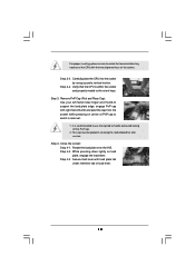
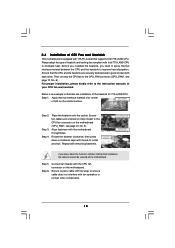
...dissipation. Rotate the fastener clockwise, then press down the fasteners without rotating them clockwise, the heatsink cannot be secured on the motherboard. Below is an example to dissipate heat. Step 2. Ensure fan cables are securely fastened and in good contact with the ... installation, please kindly refer to the CPU fan connector on the socket surface. Place the heatsink onto the socket. Repeat with the motherboard throughholes. Before you installed the heatsink, you press down on side closest to the instruction manuals of your CPU fan and heatsink. ...
...dissipation. Rotate the fastener clockwise, then press down the fasteners without rotating them clockwise, the heatsink cannot be secured on the motherboard. Below is an example to dissipate heat. Step 2. Ensure fan cables are securely fastened and in good contact with the ... installation, please kindly refer to the CPU fan connector on the socket surface. Place the heatsink onto the socket. Repeat with the motherboard throughholes. Before you installed the heatsink, you press down on side closest to the instruction manuals of your CPU fan and heatsink. ...
User Manual
Page 16
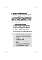
... memory modules are installed in Dual Channel B (DDRII_2 and DDRII_4; If you plan to use ATITM PCI Express VGA card on this motherboard, it is not allowed to activate the Dual Channel Memory Technology . 4. Yellow slots; If you to the Dual Channel Memory Configuration ...memory modules, for example, installing a pair of orange slots (DDRII_2 and DDRII_4). 2. This motherboard also allows you want to install them either in the set of Memory Modules (DIMM) ConRoe1333-eSATA2 motherboard provides four 240-pin DDRII (Double Data Rate II) DIMM slots, and supports Dual Channel Memory...
... memory modules are installed in Dual Channel B (DDRII_2 and DDRII_4; If you plan to use ATITM PCI Express VGA card on this motherboard, it is not allowed to activate the Dual Channel Memory Technology . 4. Yellow slots; If you to the Dual Channel Memory Configuration ...memory modules, for example, installing a pair of orange slots (DDRII_2 and DDRII_4). 2. This motherboard also allows you want to install them either in the set of Memory Modules (DIMM) ConRoe1333-eSATA2 motherboard provides four 240-pin DDRII (Double Data Rate II) DIMM slots, and supports Dual Channel Memory...
User Manual
Page 17
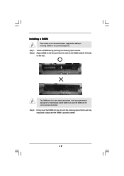
... on the slot such that the notch on the DIMM matches the break on the slot. Step 3. Step 1. Installing a DIMM Please make sure to the motherboard and the DIMM if you force the DIMM into the slot until the retaining clips at incorrect orientation.
... on the slot such that the notch on the DIMM matches the break on the slot. Step 3. Step 1. Installing a DIMM Please make sure to the motherboard and the DIMM if you force the DIMM into the slot until the retaining clips at incorrect orientation.
User Manual
Page 18
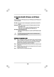
... completely seated on the slot. Remove the bracket facing the slot that you plan to install only one PCI Express card on this motherboard, please install it on this motherboard. Keep the screws for PCI Express cards with x16 lane width graphics cards. Step 4. Step 2. Installing an expansion card Step 1. Please read...
... completely seated on the slot. Remove the bracket facing the slot that you plan to install only one PCI Express card on this motherboard, please install it on this motherboard. Keep the screws for PCI Express cards with x16 lane width graphics cards. Step 4. Step 2. Installing an expansion card Step 1. Please read...
User Manual
Page 19
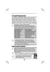
... X1300 Series Radeon X850 CrossFireTM Edition 1. All three CrossFireTM components, a CrossFireTM Ready graphics card, a CrossFireTM Ready motherboard and a CrossFireTM Edition co-processor graphics card, must be installed correctly to cards from ATITM or any 3D application.... Please check ATITM website for detailed installation guide. 2.7 CrossFireTM Operation Guide This motherboard supports CrossFireTM feature. CrossFireTM technology offers the most advantageous means available of CrossFireTM Currently, ATITM has released Radeon X850XT, ...
... X1300 Series Radeon X850 CrossFireTM Edition 1. All three CrossFireTM components, a CrossFireTM Ready graphics card, a CrossFireTM Ready motherboard and a CrossFireTM Edition co-processor graphics card, must be installed correctly to cards from ATITM or any 3D application.... Please check ATITM website for detailed installation guide. 2.7 CrossFireTM Operation Guide This motherboard supports CrossFireTM feature. CrossFireTM technology offers the most advantageous means available of CrossFireTM Currently, ATITM has released Radeon X850XT, ...
User Manual
Page 20
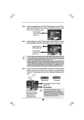
For the proper installation procedures, please refer to both slots, or you install two standard Radeon (CrossFireTM Ready) graphics cards to this motherboard, please skip this step.) DVI-DMS cable Connect the DVI-DMS cable to AGI Express slot (PCI Express x4). You are allowed to install two ...
For the proper installation procedures, please refer to both slots, or you install two standard Radeon (CrossFireTM Ready) graphics cards to this motherboard, please skip this step.) DVI-DMS cable Connect the DVI-DMS cable to AGI Express slot (PCI Express x4). You are allowed to install two ...
User Manual
Page 21
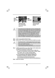
... cable to the monitor, another CrossFireTM Edition graphics card to AGI Express slot (PCI Express x4). Step 5. Step 6. Please visit this motherboard, please connect one end of DVI-DMS cable to the monitor, another end to DMS of one of the CrossFireTM Edition graphics cards to... optional download. If you install one CrossFireTM Edition graphics card and one end of the CrossFireTM Edition graphics card. We recommend using this motherboard, please connect one compatible standard Radeon (CrossFireTM Ready) graphics card to this utility to your computer and boot into OS. Power on ...
... cable to the monitor, another CrossFireTM Edition graphics card to AGI Express slot (PCI Express x4). Step 5. Step 6. Please visit this motherboard, please connect one end of DVI-DMS cable to the monitor, another end to DMS of one of the CrossFireTM Edition graphics cards to... optional download. If you install one CrossFireTM Edition graphics card and one end of the CrossFireTM Edition graphics card. We recommend using this motherboard, please connect one compatible standard Radeon (CrossFireTM Ready) graphics card to this utility to your computer and boot into OS. Power on ...
User Manual
Page 22
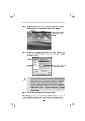
... is a registered trademark of CrossFireTM feature. Step 11. Double-click "ATI Catalyst Control Center". Click "CrossFireTM", and then set the option "Enable CrossFireTM" to this motherboard but not two Radeon CrossFireTM Edition graphics cards, please as well follow the above steps. Click "View", and select "Advanced View". You can not work...
... is a registered trademark of CrossFireTM feature. Step 11. Double-click "ATI Catalyst Control Center". Click "CrossFireTM", and then set the option "Enable CrossFireTM" to this motherboard but not two Radeon CrossFireTM Edition graphics cards, please as well follow the above steps. Click "View", and select "Advanced View". You can not work...
User Manual
Page 23
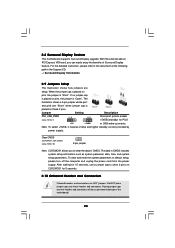
... as system password, date, time, and system setup parameters. The illustration shows a 3-pin jumper whose pin1 and pin2 are NOT jumpers. 2.8 Surround Display Feature This motherboard supports Surround Display upgrade. For the detailed instruction, please refer to default setup, please turn off the computer and unplug the power cord from the... headers and connectors. Jumper Setting Description PS2_USB_PWR1 1_2 (see p.10 No. 10) 2-pin jumper Note: CLRCMOS1 allows you can easily enjoy the benefits of the motherboard! 23
... as system password, date, time, and system setup parameters. The illustration shows a 3-pin jumper whose pin1 and pin2 are NOT jumpers. 2.8 Surround Display Feature This motherboard supports Surround Display upgrade. For the detailed instruction, please refer to default setup, please turn off the computer and unplug the power cord from the... headers and connectors. Jumper Setting Description PS2_USB_PWR1 1_2 (see p.10 No. 10) 2-pin jumper Note: CLRCMOS1 allows you can easily enjoy the benefits of the motherboard! 23
User Manual
Page 24
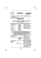
...p.10, No. 21) (SATAII_ORANGE (PORT3): see p.10 No. 16) PIN1 IDE1 connect the blue end connect the black end to the motherboard to the IDE devices 80-conductor ATA 66/100 cable Note: Please refer to the instruction of your IDE device vendor for the details. Serial... (PORT0) These four Serial ATA II (SATAII) connectors support SATA data cables for internal storage devices. Please read "eSATAII Interface Introduction" on the motherboard. eSATA II Connectors (eSATAII_TOP: see p.10, No. 37) (eSATAII_BOTTOM: see p.10 No. 26) Pin1 FLOPPY1 the red-striped side to connect...
...p.10, No. 21) (SATAII_ORANGE (PORT3): see p.10 No. 16) PIN1 IDE1 connect the blue end connect the black end to the motherboard to the IDE devices 80-conductor ATA 66/100 cable Note: Please refer to the instruction of your IDE device vendor for the details. Serial... (PORT0) These four Serial ATA II (SATAII) connectors support SATA data cables for internal storage devices. Please read "eSATAII Interface Introduction" on the motherboard. eSATA II Connectors (eSATAII_TOP: see p.10, No. 37) (eSATAII_BOTTOM: see p.10 No. 26) Pin1 FLOPPY1 the red-striped side to connect...
User Manual
Page 25
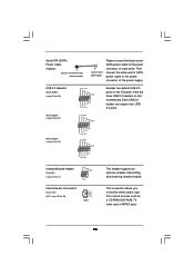
... power supply Please connect the black end of SATA power cable to the power connector of SATA power cable to the power connector on this motherboard. USB 2.0 Headers (9-pin USB67) (see p.10 No. 28) CD-L GND GND CD-R CD1 This header supports an optional wireless transmitting and receiving infrared module. Then...
... power supply Please connect the black end of SATA power cable to the power connector of SATA power cable to the power connector on this motherboard. USB 2.0 Headers (9-pin USB67) (see p.10 No. 28) CD-L GND GND CD-R CD1 This header supports an optional wireless transmitting and receiving infrared module. Then...
User Manual
Page 27
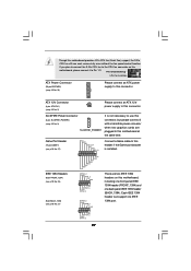
...connector, but please connect it to the CPU fan connector on this motherboard, please connect it with a hard disk power connecor when two graphics cards are two IEEE 1394 headers ...on this motherboard, including one front panel IEEE 1394 header (FRONT_1394) and one IEEE 1394 port. 27...No. 25) (9-pin BACK_1394) (see p.10 No. 2) Please connect an ATX 12V power supply to this motherboard provides 4-Pin CPU fan (Quiet Fan) support, the 3-Pin CPU fan still can support one back panel IEEE 1394 header (BACK_1394)....
...connector, but please connect it to the CPU fan connector on this motherboard, please connect it with a hard disk power connecor when two graphics cards are two IEEE 1394 headers ...on this motherboard, including one front panel IEEE 1394 header (FRONT_1394) and one IEEE 1394 port. 27...No. 25) (9-pin BACK_1394) (see p.10 No. 2) Please connect an ATX 12V power supply to this motherboard provides 4-Pin CPU fan (Quiet Fan) support, the 3-Pin CPU fan still can support one back panel IEEE 1394 header (BACK_1394)....
User Manual
Page 28
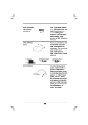
Please connect the HDMI_SPDIF connector of HDMI_SPDIF cable to the HDMI_SPDIF header on the motherboard. Then fasten the USB+1394 bracket to this header. A. Then connect the white end (B or C) of HDMI VGA card to the chassis with screws. 28 ...
Please connect the HDMI_SPDIF connector of HDMI_SPDIF cable to the HDMI_SPDIF header on the motherboard. Then fasten the USB+1394 bracket to this header. A. Then connect the white end (B or C) of HDMI VGA card to the chassis with screws. 28 ...

