User Manual
Page 3
... 6 1.3 Minimum Hardware Requirement Table for Windows® VistaTM Premium 2007 and Basic Logo 9 1.4 Motherboard Layout 10 1.5 ASRock 8CH_eSATAII I/O 11 2 Installation 12 2.1 Screw Holes 12 2.2 Pre-installation Precautions 12 2.3 CPU Installation 13 2.4 Installation of Heatsink and CPU fan 15 2.5 Installation of Memory Modules (DIMM 16 2.6 Expansion Slots 18 2.7 CrossFireTM Operation Guide 19 2.8 Surround Display...
... 6 1.3 Minimum Hardware Requirement Table for Windows® VistaTM Premium 2007 and Basic Logo 9 1.4 Motherboard Layout 10 1.5 ASRock 8CH_eSATAII I/O 11 2 Installation 12 2.1 Screw Holes 12 2.2 Pre-installation Precautions 12 2.3 CPU Installation 13 2.4 Installation of Heatsink and CPU fan 15 2.5 Installation of Memory Modules (DIMM 16 2.6 Expansion Slots 18 2.7 CrossFireTM Operation Guide 19 2.8 Surround Display...
User Manual
Page 4
... 43 2.20 Untied Overclocking Technology 44 3 BIOS SETUP UTILITY 45 3.1 Introduction 45 3.1.1 BIOS Menu Bar 45 3.1.2 Navigation Keys 46 3.2 Main Screen 46 3.3 Advanced Screen 46 3.3.1 CPU Configuration 47 3.3.2 Chipset Configuration 49 3.3.3 ACPI Configuration 51 3.3.4 IDE Configuration 52 3.3.5 PCIPnP Configuration 54 3.3.6 Floppy Configuration 55 3.3.7 Super IO Configuration 55 3.3.8 USB Configuration 57 3.4 Hardware...
... 43 2.20 Untied Overclocking Technology 44 3 BIOS SETUP UTILITY 45 3.1 Introduction 45 3.1.1 BIOS Menu Bar 45 3.1.2 Navigation Keys 46 3.2 Main Screen 46 3.3 Advanced Screen 46 3.3.1 CPU Configuration 47 3.3.2 Chipset Configuration 49 3.3.3 ACPI Configuration 51 3.3.4 IDE Configuration 52 3.3.5 PCIPnP Configuration 54 3.3.6 Floppy Configuration 55 3.3.7 Super IO Configuration 55 3.3.8 USB Configuration 57 3.4 Hardware...
User Manual
Page 5
.... You may find the latest VGA cards and CPU support lists on ASRock website without notice. In case any modifications of the Support CD. ASRock website http://www.asrock.com 1.1 Package Contents ASRock ConRoe1333-eSATA2 Motherboard (ATX Form Factor: 12.0-in x 8.6-in, 30.5 cm x 21.8 cm) ASRock ConRoe1333-eSATA2 Quick Installation Guide ASRock ConRoe1333-eSATA2 Support CD One 80-conductor Ultra ATA 66...
.... You may find the latest VGA cards and CPU support lists on ASRock website without notice. In case any modifications of the Support CD. ASRock website http://www.asrock.com 1.1 Package Contents ASRock ConRoe1333-eSATA2 Motherboard (ATX Form Factor: 12.0-in x 8.6-in, 30.5 cm x 21.8 cm) ASRock ConRoe1333-eSATA2 Quick Installation Guide ASRock ConRoe1333-eSATA2 Support CD One 80-conductor Ultra ATA 66...
User Manual
Page 6
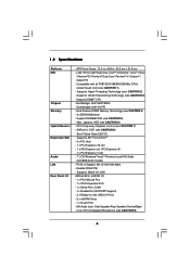
Supports Hyper-Threading Technology (see CAUTION 6) - capacity: 4GB (see CAUTION 2) - PCIE x1 Gigabit LAN 10/100/1000 Mb/s - 1.2 Specifications Platform CPU Chipset Memory Hybrid Booster Expansion Slot Audio LAN Rear Panel I /O - 1 x PS/2 Mouse Port - 1 x PS/2 Keyboard Port - 1 x Serial ... DDRII Memory Technology (see CAUTION 5) - Support DDRII667/533 (see CAUTION 4) - 4 x DDRII DIMM slots - Realtek RTL8111B - CPU Frequency Stepless Control (see CAUTION 8) - ASRock U-COP (see CAUTION 7) - HD Audio Jack: Side Speaker/Rear Speaker/Central/Bass/ Line in , 30.5 cm x 21.8 cm...
Supports Hyper-Threading Technology (see CAUTION 6) - capacity: 4GB (see CAUTION 2) - PCIE x1 Gigabit LAN 10/100/1000 Mb/s - 1.2 Specifications Platform CPU Chipset Memory Hybrid Booster Expansion Slot Audio LAN Rear Panel I /O - 1 x PS/2 Mouse Port - 1 x PS/2 Keyboard Port - 1 x Serial ... DDRII Memory Technology (see CAUTION 5) - Support DDRII667/533 (see CAUTION 4) - 4 x DDRII DIMM slots - Realtek RTL8111B - CPU Frequency Stepless Control (see CAUTION 8) - ASRock U-COP (see CAUTION 7) - HD Audio Jack: Side Speaker/Rear Speaker/Central/Bass/ Line in , 30.5 cm x 21.8 cm...
User Manual
Page 7
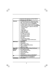
...supports 2 x IDE devices) - 1 x Floppy connector - 1 x IR header - 1 x Game header - 1 x HDMI_SPDIF header - 2 x IEEE 1394 headers - CPU Quiet Fan - Connector BIOS Feature Support CD Hardware Monitor OS Certifications Free Bundle: USB+1394 bracket, providing 2 additional USB 2.0 ports and 1 IEEE 1394 port - 4 x ... (see CAUTION 10) - 2 x eSATAII 3.0Gb/s connectors (shared with 2 SATAII connectors), support "Hot Plug" function (see CAUTION 13) - CPU/Chassis FAN connector - 20 pin ATX power connector - 4 pin 12V power connector - SLI/XFIRE power connector - CD in header - Front panel ...
...supports 2 x IDE devices) - 1 x Floppy connector - 1 x IR header - 1 x Game header - 1 x HDMI_SPDIF header - 2 x IEEE 1394 headers - CPU Quiet Fan - Connector BIOS Feature Support CD Hardware Monitor OS Certifications Free Bundle: USB+1394 bracket, providing 2 additional USB 2.0 ports and 1 IEEE 1394 port - 4 x ... (see CAUTION 10) - 2 x eSATAII 3.0Gb/s connectors (shared with 2 SATAII connectors), support "Hot Plug" function (see CAUTION 13) - CPU/Chassis FAN connector - 20 pin ATX power connector - 4 pin 12V power connector - SLI/XFIRE power connector - CD in header - Front panel ...
User Manual
Page 8
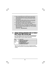
...the installation guide of "Hyper Threading Technology", please check page 48. 3. Please check the table below for details. 4. CPU FSB Frequency Memory Support Frequency 1333 DDRII533*, DDRII667 1066 DDRII533, DDRII667 800 DDRII400, DDRII533, DDRII667 533 DDRII400, DDRII533 * When... you implement Dual Channel Memory Technology, make sure to spray thermal grease between the CPU and the heatsink when you adopt a DDRII533 memory module. 6. Under this motherboard supports 2-channel, 4-channel, 6-channel, and 8-...
...the installation guide of "Hyper Threading Technology", please check page 48. 3. Please check the table below for details. 4. CPU FSB Frequency Memory Support Frequency 1333 DDRII533*, DDRII667 1066 DDRII533, DDRII667 800 DDRII400, DDRII533, DDRII667 533 DDRII400, DDRII533 * When... you implement Dual Channel Memory Technology, make sure to spray thermal grease between the CPU and the heatsink when you adopt a DDRII533 memory module. 6. Under this motherboard supports 2-channel, 4-channel, 6-channel, and 8-...
User Manual
Page 9
... As long as we have the latest driver, we will update it to qualify for Windows® VistaTM Premium 2007 logo. 9 ASRock website http://www.asrock.com 1.3 Minimum Hardware Requirement Table for Windows® VistaTM Premium 2007 and Basic Logo For system integrators and users who purchase this ... Windows® VistaTM 64-bit / VistaTM / XP 64-bit / XP SP1 or SP2 / 2000 SP4. 13. Power Management for minimum hardware requirements. CPU Memory VGA Celeron D 326 1GB system memory (Premium) 512MB Single Channel (Basic) DX9.0 with WDDM Driver with 128bit VGA memory (Premium) with 64bit VGA...
... As long as we have the latest driver, we will update it to qualify for Windows® VistaTM Premium 2007 logo. 9 ASRock website http://www.asrock.com 1.3 Minimum Hardware Requirement Table for Windows® VistaTM Premium 2007 and Basic Logo For system integrators and users who purchase this ... Windows® VistaTM 64-bit / VistaTM / XP 64-bit / XP SP1 or SP2 / 2000 SP4. 13. Power Management for minimum hardware requirements. CPU Memory VGA Celeron D 326 1GB system memory (Premium) 512MB Single Channel (Basic) DX9.0 with WDDM Driver with 128bit VGA memory (Premium) with 64bit VGA...

User Manual
Page 13
...to fully open position at approximately 135 degrees. Pin1 orientation key notch orientation key notch Pin1 alignment key alignment key 775-LAND CPU 775-Pin Socket 13 black line black line Rotate the load lever to fully open position at approximately 100 degrees. Insert the 775-LAND... CPU: Step 2-1. Step 1-2. Step 1-3. Locate Pin1 and the two orientation key notches. Disengaging the lever by the edges where are marked with IHS ...
...to fully open position at approximately 135 degrees. Pin1 orientation key notch orientation key notch Pin1 alignment key alignment key 775-LAND CPU 775-Pin Socket 13 black line black line Rotate the load lever to fully open position at approximately 100 degrees. Insert the 775-LAND... CPU: Step 2-1. Step 1-2. Step 1-3. Locate Pin1 and the two orientation key notches. Disengaging the lever by the edges where are marked with IHS ...
User Manual
Page 14
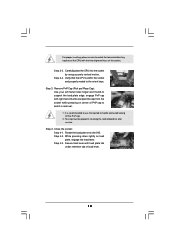
... recommended to use the cap tab to match the two orientation key notches of the CPU with the two alignment keys of the socket. Remove PnP Cap (Pick and Place Cap): Use your left hand index finger and thumb to support ...
... recommended to use the cap tab to match the two orientation key notches of the CPU with the two alignment keys of the socket. Remove PnP Cap (Pick and Place Cap): Use your left hand index finger and thumb to support ...
User Manual
Page 15
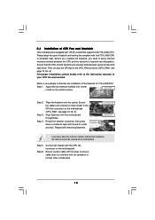
... to dissipate heat. Ensure fan cables are securely fastened and in good contact with tie-wrap to the CPU fan connector on the socket surface. Ensure that supports Intel 775-LAND CPU. Step 1. Apply thermal interface material onto center of IHS on the motherboard (CPU_FAN1, see page 10, No.... throughholes. Before you installed the heatsink, you press down on the motherboard. Connect fan header with the CPU fan connector on fastener caps with 775-Pin socket that the CPU and the heatsink are oriented on side closest to ensure cable does not interfere with Intel 775-LAND...
... to dissipate heat. Ensure fan cables are securely fastened and in good contact with tie-wrap to the CPU fan connector on the socket surface. Ensure that supports Intel 775-LAND CPU. Step 1. Apply thermal interface material onto center of IHS on the motherboard (CPU_FAN1, see page 10, No.... throughholes. Before you installed the heatsink, you press down on the motherboard. Connect fan header with the CPU fan connector on fastener caps with 775-Pin socket that the CPU and the heatsink are oriented on side closest to ensure cable does not interfere with Intel 775-LAND...
User Manual
Page 26
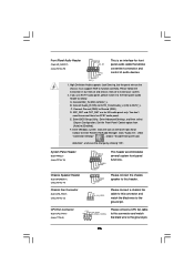
... OUT2_L. Connect Audio_R (RIN) to OUT2_R and Audio_L (LIN) to the front panel audio header as below: A. D. Enter BIOS Setup Utility. CPU Fan Connector (4-pin CPU_FAN1) (see p.11 No. 6) +12V CPU_FAN_SPEED GND FAN_SPEED_CONTROL 1 2 3 4 Please connect a CPU fan cable to this connector and match the black wire to enter Realtek HD Audio Manager.
... OUT2_L. Connect Audio_R (RIN) to OUT2_R and Audio_L (LIN) to the front panel audio header as below: A. D. Enter BIOS Setup Utility. CPU Fan Connector (4-pin CPU_FAN1) (see p.11 No. 6) +12V CPU_FAN_SPEED GND FAN_SPEED_CONTROL 1 2 3 4 Please connect a CPU fan cable to this connector and match the black wire to enter Realtek HD Audio Manager.
User Manual
Page 27
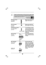
...this connector. There are plugged to this motherboard at the same time. Though this connector. If you plan to connect the 3-Pin CPU fan to the CPU fan connector on this motherboard, please connect it to use this connector, but please connect it with a hard disk power connecor ...12V RXTPBP_0 GND RXTPAP_0 RXTPAM_0 GND RXTPBM_0 +12V GND 1 +12V RXTPBP_0 GND RXTPAP_0 Connect a Game cable to this motherboard provides 4-Pin CPU fan (Quiet Fan) support, the 3-Pin CPU fan still can support one back panel IEEE 1394 header (BACK_1394). ATX 12V Connector (4-pin ATX12V1) (see p.10 No. 3) SLI/...
...this connector. There are plugged to this motherboard at the same time. Though this connector. If you plan to connect the 3-Pin CPU fan to the CPU fan connector on this motherboard, please connect it to use this connector, but please connect it with a hard disk power connecor ...12V RXTPBP_0 GND RXTPAP_0 RXTPAM_0 GND RXTPBM_0 +12V GND 1 +12V RXTPBP_0 GND RXTPAP_0 Connect a Game cable to this motherboard provides 4-Pin CPU fan (Quiet Fan) support, the 3-Pin CPU fan still can support one back panel IEEE 1394 header (BACK_1394). ATX 12V Connector (4-pin ATX12V1) (see p.10 No. 3) SLI/...
User Manual
Page 44
... is untied during overclocking, FSB enjoys better margin due to fixed PCI / PCIE buses. Please refer to [CPU, PCIE, Async.]. Before you enable Untied Overclocking function, please enter "Overclock Mode" option of BIOS setup to set the selection from [Auto] to the warning ...
... is untied during overclocking, FSB enjoys better margin due to fixed PCI / PCIE buses. Please refer to [CPU, PCIE, Async.]. Before you enable Untied Overclocking function, please enter "Overclock Mode" option of BIOS setup to set the selection from [Auto] to the warning ...
User Manual
Page 46
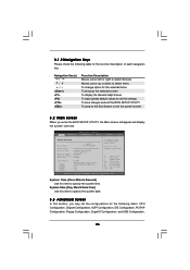
...Boot Security Exit System Overview System Time System Date [14:00:09] [Fri 04/20/2006] BIOS Version : ConRoe1333-eSATA2 BIOS P1.00 Processor Type : Intel (R) CPU 3.40 GHz (64bit supported) Processor Speed : 3400 MHz Microcode Update : F34/17 Cache Size : 1024KB Total Memory... and Exit Exit v02.54 (C) Copyright 1985-2005, American Megatrends, Inc. 3.1.2 Navigation Keys Please check the following items: CPU Configuration, Chipset Configuration, ACPI Configuration, IDE Configuration, PCIPnP Configuration, Floppy Configuration, SuperIO Configuration, and USB Configuration. 46 Use ...
...Boot Security Exit System Overview System Time System Date [14:00:09] [Fri 04/20/2006] BIOS Version : ConRoe1333-eSATA2 BIOS P1.00 Processor Type : Intel (R) CPU 3.40 GHz (64bit supported) Processor Speed : 3400 MHz Microcode Update : F34/17 Cache Size : 1024KB Total Memory... and Exit Exit v02.54 (C) Copyright 1985-2005, American Megatrends, Inc. 3.1.2 Navigation Keys Please check the following items: CPU Configuration, Chipset Configuration, ACPI Configuration, IDE Configuration, PCIPnP Configuration, Floppy Configuration, SuperIO Configuration, and USB Configuration. 46 Use ...
User Manual
Page 47
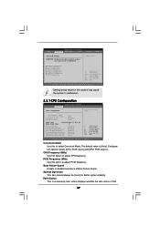
...Auto] Ratio Status Ratio Actual Value Unlocked (Max :17, Min : 14) 17 Enhance Halt State Max CPUID Value Limit Intel (R) Virtualization tech. CPU Thermal Throttling No-Excute Memory Protection Hyper Threading Technology Intel (R) SpeedStep(tm) tech. [Disabled] [Disabled] [Enabled] [Enabled] [Disabled] [Enabled]...Auto] for better system stability. Configuration options: [Auto], [CPU, PCIE, Sync.] and [CPU, PCIE, Async.]. Ratio Status This is [Auto]. PCIE Frequency (MHz) Use this option to adjust CPU frequency. CPU Frequency (MHz) Use this option to adjust PCIE frequency. ...
...Auto] Ratio Status Ratio Actual Value Unlocked (Max :17, Min : 14) 17 Enhance Halt State Max CPUID Value Limit Intel (R) Virtualization tech. CPU Thermal Throttling No-Excute Memory Protection Hyper Threading Technology Intel (R) SpeedStep(tm) tech. [Disabled] [Disabled] [Enabled] [Enabled] [Disabled] [Enabled]...Auto] for better system stability. Configuration options: [Auto], [CPU, PCIE, Sync.] and [CPU, PCIE, Async.]. Ratio Status This is [Auto]. PCIE Frequency (MHz) Use this option to adjust CPU frequency. CPU Frequency (MHz) Use this option to adjust PCIE frequency. ...

User Manual
Page 48
...Microsoft® Windows® XP. motherboard is set to [Enabled], a VMM (Virtual Machine Architecture) can prevent data pages from overheated. If the CPU you adopt supports EIST (Intel (R) SpeedStep(tm) tech.), and you changing the ratio value of this item appear to allow you plan to execute ...is unlocked, you will find an item Ratio CMOS Setting appears to the IA-32 Intel Architecture. This should be hidden if the installed CPU does not support Hyper-Threading technology. 48 No-Excute Memory Protection No-Execution (NX) Memory Protection Technology is a read-only item, which...
...Microsoft® Windows® XP. motherboard is set to [Enabled], a VMM (Virtual Machine Architecture) can prevent data pages from overheated. If the CPU you adopt supports EIST (Intel (R) SpeedStep(tm) tech.), and you changing the ratio value of this item appear to allow you plan to execute ...is unlocked, you will find an item Ratio CMOS Setting appears to the IA-32 Intel Architecture. This should be hidden if the installed CPU does not support Hyper-Threading technology. 48 No-Excute Memory Protection No-Execution (NX) Memory Protection Technology is a read-only item, which...
User Manual
Page 49
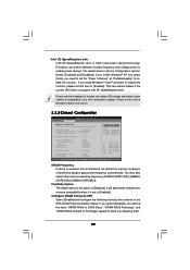
... select other value as "Portable/Laptop" to system stability or compatibility issue with some power supplies. Configuration options: [Auto], [Enabled] and [Disabled]. You may reduce CPU voltage and lead to enable this option is selected, the motherboard will detect the memory module(s) inserted and assigns appropriate frequency automatically. Configure DRAM Timing.... Intel (R) SpeedStep(tm) tech. Intel (R) SpeedStep(tm) tech. is [Auto]. Please set this item to enable power savings. It will be hidden if the current CPU does not support Intel (R) SpeedStep(tm) tech..
... select other value as "Portable/Laptop" to system stability or compatibility issue with some power supplies. Configuration options: [Auto], [Enabled] and [Disabled]. You may reduce CPU voltage and lead to enable this option is selected, the motherboard will detect the memory module(s) inserted and assigns appropriate frequency automatically. Configure DRAM Timing.... Intel (R) SpeedStep(tm) tech. Intel (R) SpeedStep(tm) tech. is [Auto]. Please set this item to enable power savings. It will be hidden if the current CPU does not support Intel (R) SpeedStep(tm) tech..

User Manual
Page 57
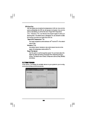
... 1985-2005, American Megatrends, Inc. etc. BIOS SETUP UTILITY Main Advanced H/W Monitor Boot Security Exit Hardware Health Event Monitoring CPU Temperature M / B Temperature : 37 C / 98 F : 31 C / 87 F Target Fan Speed Fast Middle Slow CPU Fan Speed Chassis Fan Speed : 3400 RPM : N/A Vcore + 3.30V + 5.00V + 12.00V : 1.629V :... the support to auto-detect; Legacy USB Support Use this item to enable or disable the use of the CPU temperature, motherboard temperature, CPU fan speed, chassis fan speed, and the critical voltage. Or you to monitor the status of the hardware on...
... 1985-2005, American Megatrends, Inc. etc. BIOS SETUP UTILITY Main Advanced H/W Monitor Boot Security Exit Hardware Health Event Monitoring CPU Temperature M / B Temperature : 37 C / 98 F : 31 C / 87 F Target Fan Speed Fast Middle Slow CPU Fan Speed Chassis Fan Speed : 3400 RPM : N/A Vcore + 3.30V + 5.00V + 12.00V : 1.629V :... the support to auto-detect; Legacy USB Support Use this item to enable or disable the use of the CPU temperature, motherboard temperature, CPU fan speed, chassis fan speed, and the critical voltage. Or you to monitor the status of the hardware on...
User Manual
Page 58
... is [Disabled]. If you set this option as [Enabled], you will display the available devices on your system for you adjusting them. Target CPU Temperature ( C) The target temperature will be between 45 C and 65 C. Target Fan Speed Use this option to configure the boot settings and...- ROM C] [USB] Select Screen Select Item Enter Go to identify the temperature of the target CPU temperature will be within 2 C. The default value is [2], which means the error of CPU fan. CD - CPU Quiet Fan This item allows you choose. You can freely adjust the target fan speed according to...
... is [Disabled]. If you set this option as [Enabled], you will display the available devices on your system for you adjusting them. Target CPU Temperature ( C) The target temperature will be between 45 C and 65 C. Target Fan Speed Use this option to configure the boot settings and...- ROM C] [USB] Select Screen Select Item Enter Go to identify the temperature of the target CPU temperature will be within 2 C. The default value is [2], which means the error of CPU fan. CD - CPU Quiet Fan This item allows you choose. You can freely adjust the target fan speed according to...
Quick Installation Guide
Page 2
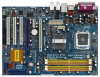
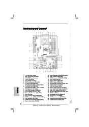
... PCI Express x1 Slot (PCIE2) 35 ATX Power Connector (ATXPWR1) 36 eSATAII Connector (eSATAII_BOTTOM) 37 eSATAII Connector (eSATAII_TOP) 2 ASRock ConRoe1333-eSATA2 Motherboard Motherboard Layout English 1 PS2_USB_PWR1 Jumper 2 ATX 12V Connector (ATX12V1) 3 SLI / XFIRE Power Connector 4 775-Pin CPU Socket 5 North Bridge Controller 6 CPU Fan Connector (CPU_FAN1) 7 2 x 240-pin DDRII DIMM Slots (Dual Channel A: DDRII_1, DDRII_3;
... PCI Express x1 Slot (PCIE2) 35 ATX Power Connector (ATXPWR1) 36 eSATAII Connector (eSATAII_BOTTOM) 37 eSATAII Connector (eSATAII_TOP) 2 ASRock ConRoe1333-eSATA2 Motherboard Motherboard Layout English 1 PS2_USB_PWR1 Jumper 2 ATX 12V Connector (ATX12V1) 3 SLI / XFIRE Power Connector 4 775-Pin CPU Socket 5 North Bridge Controller 6 CPU Fan Connector (CPU_FAN1) 7 2 x 240-pin DDRII DIMM Slots (Dual Channel A: DDRII_1, DDRII_3;


