User Manual
Page 3
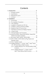
...1.3 Motherboard Layout 12 1.4 I/O Panel 13 2 Installation 14 2.1 Screw Holes 14 2.2 Pre-installation Precautions 14 2.3 CPU Installation 15 2.4 Installation of Heatsink and CPU fan 17 2.5 Installation of Memory Modules (DIMM 18 2.6 Expansion Slots (PCI Express Slots 19 2.7 Dual Monitor and Surround Display Features 20 2.8 Jumpers Setup 23 2.9 Onboard Headers and Connectors 24 2.10 Serial ATA (SATA) / Serial ATA2 (SATA2) / Serial ATA3 (SATA3) Hard Disks Installation 28 2.11 Hot Plug for SATA / SATA2 / SATA3 HDDs 28 2.12 SATA / SATA2 / SATA3 HDD Hot Plug Feature and Operation Guide...
...1.3 Motherboard Layout 12 1.4 I/O Panel 13 2 Installation 14 2.1 Screw Holes 14 2.2 Pre-installation Precautions 14 2.3 CPU Installation 15 2.4 Installation of Heatsink and CPU fan 17 2.5 Installation of Memory Modules (DIMM 18 2.6 Expansion Slots (PCI Express Slots 19 2.7 Dual Monitor and Surround Display Features 20 2.8 Jumpers Setup 23 2.9 Onboard Headers and Connectors 24 2.10 Serial ATA (SATA) / Serial ATA2 (SATA2) / Serial ATA3 (SATA3) Hard Disks Installation 28 2.11 Hot Plug for SATA / SATA2 / SATA3 HDDs 28 2.12 SATA / SATA2 / SATA3 HDD Hot Plug Feature and Operation Guide...

User Manual
Page 5
... conforming to ASRock's commitment to AHCI mode. Because the motherboard specifications and the BIOS software might be updated, the content of this manual occur, the updated version will be available on ASRock website as well. You may find the latest VGA cards and CPU support lists on ASRock website without notice. For the BIOS setup, please refer to the "User Manual" in , 22.6 cm x 18.3 cm) ASRock B75M-DGS Quick Installation Guide ASRock B75M-DGS Support CD 2 x Serial ATA (SATA) Data Cables (Optional) 1 x I/O Panel Shield ASRock Reminds...
... conforming to ASRock's commitment to AHCI mode. Because the motherboard specifications and the BIOS software might be updated, the content of this manual occur, the updated version will be available on ASRock website as well. You may find the latest VGA cards and CPU support lists on ASRock website without notice. For the BIOS setup, please refer to the "User Manual" in , 22.6 cm x 18.3 cm) ASRock B75M-DGS Quick Installation Guide ASRock B75M-DGS Support CD 2 x Serial ATA (SATA) Data Cables (Optional) 1 x I/O Panel Shield ASRock Reminds...
User Manual
Page 10
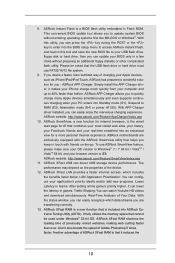
... charging your PC enters into ASRock Extreme Tuning Utility (AXTU). ASRock XFast RAM shortens the loading time of ASRock XFast RAM is the smart start page for you can update your application's priority ideally and/or add new programs. Lower Latency in Game: After setting online game's priority higher, it reduces the 10 ASRock APP Charger. To use FAT32/16/12 file system. 9. LAN Application Prioritization...
... charging your PC enters into ASRock Extreme Tuning Utility (AXTU). ASRock XFast RAM shortens the loading time of ASRock XFast RAM is the smart start page for you can update your application's priority ideally and/or add new programs. Lower Latency in Game: After setting online game's priority higher, it reduces the 10 ASRock APP Charger. To use FAT32/16/12 file system. 9. LAN Application Prioritization...
User Manual
Page 12
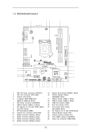
...-Pin CPU Socket 4 2 x 240-pin DDR3 DIMM Slots (DDR3_A1, DDR3_B1, Black) 5 ATX Power Connector (ATXPWR1) 6 USB 3.0 Header (USB3_2_3, Black) 7 PCI Express 3.0 x16 Slot (PCIE1, Black) 8 Intel B75 Chipset 9 SPI Flash Memory (64Mb) 10 Chassis Fan Connector (CHA_FAN1) 11 SATA2 Connector (SATA2_1, Black) 12 SATA3 Connector (SATA3_0, Gray) 13 SATA2 Connector (SATA2_2, Black) 14 SATA2 Connector (SATA2_3, Black) 15 System Panel Header (PANEL1, Black) 16 Chassis Speaker Header (SPEAKER1, Black) 17 USB 2.0 Header (USB6_7, Black) 18 USB 2.0 Header (USB4_5, Black) 19 COM Port Header (COM1...
...-Pin CPU Socket 4 2 x 240-pin DDR3 DIMM Slots (DDR3_A1, DDR3_B1, Black) 5 ATX Power Connector (ATXPWR1) 6 USB 3.0 Header (USB3_2_3, Black) 7 PCI Express 3.0 x16 Slot (PCIE1, Black) 8 Intel B75 Chipset 9 SPI Flash Memory (64Mb) 10 Chassis Fan Connector (CHA_FAN1) 11 SATA2 Connector (SATA2_1, Black) 12 SATA3 Connector (SATA3_0, Gray) 13 SATA2 Connector (SATA2_2, Black) 14 SATA2 Connector (SATA2_3, Black) 15 System Panel Header (PANEL1, Black) 16 Chassis Speaker Header (SPEAKER1, Black) 17 USB 2.0 Header (USB6_7, Black) 18 USB 2.0 Header (USB4_5, Black) 19 COM Port Header (COM1...
User Manual
Page 20
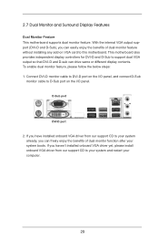
... without installing any add-on VGA card to D-Sub port on the I /O panel. Connect DVI-D monitor cable to DVI-D port on the I /O panel, and connect D-Sub monitor cable to this motherboard. 2.7 Dual Monitor and Surround Display Features Dual Monitor Feature This motherboard supports dual monitor feature. To enable dual monitor feature, please follow the below steps: 1. If you have installed onboard VGA driver from our support CD to your system already, you haven't installed onboard VGA driver yet, please install onboard VGA driver from our support CD to support dual VGA output...
... without installing any add-on VGA card to D-Sub port on the I /O panel. Connect DVI-D monitor cable to DVI-D port on the I /O panel, and connect D-Sub monitor cable to this motherboard. 2.7 Dual Monitor and Surround Display Features Dual Monitor Feature This motherboard supports dual monitor feature. To enable dual monitor feature, please follow the below steps: 1. If you have installed onboard VGA driver from our support CD to your system already, you haven't installed onboard VGA driver yet, please install onboard VGA driver from our support CD to support dual VGA output...
User Manual
Page 21
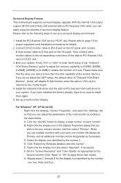
Surround Display Feature This motherboard supports surround display upgrade. Please refer to the following steps to the corresponding connectors of D-sub. Then connect other monitor cables to set up a multi-monitor display. Press or to apply these new values. Enter "Onboard VGA Share Memory" option to adjust the memory capability to [32MB], [64MB], [128MB], [256MB] or [512MB] to enable the function of the add-on PCI Express VGA card on VGA card is inserted to install them...
Surround Display Feature This motherboard supports surround display upgrade. Please refer to the following steps to the corresponding connectors of D-sub. Then connect other monitor cables to set up a multi-monitor display. Press or to apply these new values. Enter "Onboard VGA Share Memory" option to adjust the memory capability to [32MB], [64MB], [128MB], [256MB] or [512MB] to enable the function of the add-on PCI Express VGA card on VGA card is inserted to install them...
User Manual
Page 31
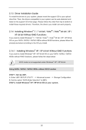
... . Using SATA / SATA2 / SATA3 HDDs without RAID functions, please follow the order from top to bottom to [IDE]. STEP 2: Install Windows® XP / XP 64-bit OS on the support CD driver page. A. Set the option "SATA Mode Selection" to install those required drivers. Enter UEFI SETUP UTILITY Advanced screen Storage Configuration. 2.13 Driver Installation Guide To install the drivers to your system, please insert the support CD to your system. 31 AHCI mode is not supported under Windows® XP / XP 64-bit.
... . Using SATA / SATA2 / SATA3 HDDs without RAID functions, please follow the order from top to bottom to [IDE]. STEP 2: Install Windows® XP / XP 64-bit OS on the support CD driver page. A. Set the option "SATA Mode Selection" to install those required drivers. Enter UEFI SETUP UTILITY Advanced screen Storage Configuration. 2.13 Driver Installation Guide To install the drivers to your system, please insert the support CD to your system. 31 AHCI mode is not supported under Windows® XP / XP 64-bit.
User Manual
Page 41
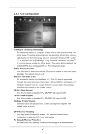
... caches. CPU C6 State Support Use this technology, such as Microsoft® Windows® XP / VistaTM / 7 is required. CPU Thermal Throttling You may select [Enabled] to enable CPU internal thermal control mechanism to keep the CPU from the chipset. Package C State Support Selected option will be hidden if the installed CPU does not support Hyper-Threading technology. No-Execute Memory Protection No-Execution (NX) Memory Protection Technology is supported through the native processor instructions HLT...
... caches. CPU C6 State Support Use this technology, such as Microsoft® Windows® XP / VistaTM / 7 is required. CPU Thermal Throttling You may select [Enabled] to enable CPU internal thermal control mechanism to keep the CPU from the chipset. Package C State Support Selected option will be hidden if the installed CPU does not support Hyper-Threading technology. No-Execute Memory Protection No-Execution (NX) Memory Protection Technology is supported through the native processor instructions HLT...
User Manual
Page 43
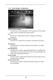
... PCIE1 Link Speed. PCIE1 Link Speed This allows you to set onboard VGA share memory feature. The default value is [Auto]. The default value is [Enabled]. The default value is [Enabled]. 43 The default value is [Disabled]. VT-d Use this option. Render Standby Use this to enable or disable Render Standby by Internal Graphics Device. The default value is [PCI Express]. Deep Render Standby This allows you to enable or disable IGPU Multi-Monitor. IGPU Multi-Monitor This allows...
... PCIE1 Link Speed. PCIE1 Link Speed This allows you to set onboard VGA share memory feature. The default value is [Auto]. The default value is [Enabled]. The default value is [Enabled]. 43 The default value is [Disabled]. VT-d Use this option. Render Standby Use this to enable or disable Render Standby by Internal Graphics Device. The default value is [PCI Express]. Deep Render Standby This allows you to enable or disable IGPU Multi-Monitor. IGPU Multi-Monitor This allows...
User Manual
Page 50
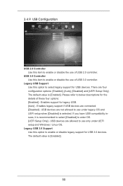
... connected. [Disabled] - Enables legacy support if USB devices are four configuration options: [Enabled], [Auto], [Disabled] and [UEFI Setup Only]. If you have USB compatibility issues, it is [Enabled]. 50 Legacy USB 3.0 Support Use this option to select legacy support for USB 3.0 devices. The default value is recommended to select [Disabled] to use under UEFI setup and Windows / Linux OS. USB devices are not allowed to enter OS. [UEFI Setup Only] - USB 3.0 Controller Use this item to enable or disable legacy support for USB devices. Legacy USB Support Use this option...
... connected. [Disabled] - Enables legacy support if USB devices are four configuration options: [Enabled], [Auto], [Disabled] and [UEFI Setup Only]. If you have USB compatibility issues, it is [Enabled]. 50 Legacy USB 3.0 Support Use this option to select legacy support for USB 3.0 devices. The default value is recommended to select [Disabled] to use under UEFI setup and Windows / Linux OS. USB devices are not allowed to enter OS. [UEFI Setup Only] - USB 3.0 Controller Use this item to enable or disable legacy support for USB devices. Legacy USB Support Use this option...
User Manual
Page 56
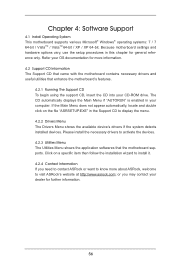
... motherboard settings and hardware options vary, use the setup procedures in your CD-ROM drive. The CD automatically displays the Main Menu if "AUTORUN" is enabled in this chapter for general reference only. Chapter 4: Software Support 4.1 Install Operating System This motherboard supports various Microsoft® Windows® operating systems: 7 / 7 64-bit / VistaTM / VistaTM 64-bit / XP / XP 64-bit. Click on the file "ASRSETUP.EXE" in the Support CD to activate the devices. 4.2.3 Utilities Menu...
... motherboard settings and hardware options vary, use the setup procedures in your CD-ROM drive. The CD automatically displays the Main Menu if "AUTORUN" is enabled in this chapter for general reference only. Chapter 4: Software Support 4.1 Install Operating System This motherboard supports various Microsoft® Windows® operating systems: 7 / 7 64-bit / VistaTM / VistaTM 64-bit / XP / XP 64-bit. Click on the file "ASRSETUP.EXE" in the Support CD to activate the devices. 4.2.3 Utilities Menu...

Quick Installation Guide
Page 2
... SATA3 Connector (SATA3_0, Gray) 13 SATA2 Connector (SATA2_2, Black) 14 SATA2 Connector (SATA2_3, Black) 15 System Panel Header (PANEL1, Black) 16 Chassis Speaker Header (SPEAKER1, Black) 17 USB 2.0 Header (USB6_7, Black) 18 USB 2.0 Header (USB4_5, Black) 19 COM Port Header (COM1) 20 Print Port Header (LPT1) 21 Front Panel Audio Header (HD_AUDIO1, Black) 22 PCI Express 2.0 x1 Slot (PCIE2, Black) 23 Infrared Module Header (IR1) 24 Chassis Intrusion Header (CI1) 25 Clear CMOS Jumper (CLRCMOS1) 26 Power Fan Connector (PWR_FAN1) 2 ASRock B75M-DGS Motherboard English
... SATA3 Connector (SATA3_0, Gray) 13 SATA2 Connector (SATA2_2, Black) 14 SATA2 Connector (SATA2_3, Black) 15 System Panel Header (PANEL1, Black) 16 Chassis Speaker Header (SPEAKER1, Black) 17 USB 2.0 Header (USB6_7, Black) 18 USB 2.0 Header (USB4_5, Black) 19 COM Port Header (COM1) 20 Print Port Header (LPT1) 21 Front Panel Audio Header (HD_AUDIO1, Black) 22 PCI Express 2.0 x1 Slot (PCIE2, Black) 23 Infrared Module Header (IR1) 24 Chassis Intrusion Header (CI1) 25 Clear CMOS Jumper (CLRCMOS1) 26 Power Fan Connector (PWR_FAN1) 2 ASRock B75M-DGS Motherboard English
Quick Installation Guide
Page 4
... you are using. For the BIOS setup, please refer to AHCI mode. More detailed information of the motherboard and step-bystep installation guide. To get better performance in Windows® 7 / 7 64-bit / VistaTM / VistaTM 64bit, it is recommended to set the BIOS option in Storage Configuration to the "User Manual" in our support CD for purchasing ASRock B75M-DGS motherboard, a reliable motherboard produced under ASRock's consistently stringent quality control. This Quick Installation Guide contains...
... you are using. For the BIOS setup, please refer to AHCI mode. More detailed information of the motherboard and step-bystep installation guide. To get better performance in Windows® 7 / 7 64-bit / VistaTM / VistaTM 64bit, it is recommended to set the BIOS option in Storage Configuration to the "User Manual" in our support CD for purchasing ASRock B75M-DGS motherboard, a reliable motherboard produced under ASRock's consistently stringent quality control. This Quick Installation Guide contains...
Quick Installation Guide
Page 9
... drive or hard drive must use ASRock SmartView feature, please make sure your OS version is Windows® 7 / 7 64 bit / VistaTM / VistaTM 64 bit, and your USB flash drive, floppy disk or hard drive, then you can lower the latency in Flash ROM. ASRock Instant Flash is the smart start page for you to quickly charge many Apple devices simultaneously and even supports continuous charging when your PC enters into the BIOS setup menu...
... drive or hard drive must use ASRock SmartView feature, please make sure your OS version is Windows® 7 / 7 64 bit / VistaTM / VistaTM 64 bit, and your USB flash drive, floppy disk or hard drive, then you can lower the latency in Flash ROM. ASRock Instant Flash is the smart start page for you to quickly charge many Apple devices simultaneously and even supports continuous charging when your PC enters into the BIOS setup menu...
Quick Installation Guide
Page 10
..., remember to update their lifespan. 14. Please be noticed that BIOS files need to be used. 20. Intel® Smart Connect Technology and Intel® USB 3.0 ports are required. 16. According to modify the system time are not supported by enabling "Dehumidifier Function". frequency of accessing your USB disk. Combo Cooler Option (C.C.O.) provides the flexible option to check with the power supply manufacturer for...
..., remember to update their lifespan. 14. Please be noticed that BIOS files need to be used. 20. Intel® Smart Connect Technology and Intel® USB 3.0 ports are required. 16. According to modify the system time are not supported by enabling "Dehumidifier Function". frequency of accessing your USB disk. Combo Cooler Option (C.C.O.) provides the flexible option to check with the power supply manufacturer for...

Quick Installation Guide
Page 17
... port on VGA card to support dual VGA output so that DVI-D and D-sub can easily enjoy the benefits of dual monitor function after your computer. 17 ASRock B75M-DGS Motherboard English If you have installed onboard VGA driver from our support CD to your system already, you can drive same or different display contents. Connect DVI-D monitor cable to DVI-D port on the I /O panel. D-Sub port DVI-D port 2. This motherboard also provides independent display controllers for...
... port on VGA card to support dual VGA output so that DVI-D and D-sub can easily enjoy the benefits of dual monitor function after your computer. 17 ASRock B75M-DGS Motherboard English If you have installed onboard VGA driver from our support CD to your system already, you can drive same or different display contents. Connect DVI-D monitor cable to DVI-D port on the I /O panel. D-Sub port DVI-D port 2. This motherboard also provides independent display controllers for...

Quick Installation Guide
Page 18
... add-on VGA card is no need to D-Sub port on PCIE1 slot. 3. Click "Extend my Windows desktop onto this motherboard. 4. Right-click the display icon and select "Attached", if necessary. G. Install the PCI Express VGA card on PCI Express VGA card driver to this monitor". Please refer to the corresponding connectors of the system memory. Then connect other monitor cables to page 17 for proper expansion card installation procedures for the second monitor. Enter "Onboard VGA Share Memory" option to adjust...
... add-on VGA card is no need to D-Sub port on PCIE1 slot. 3. Click "Extend my Windows desktop onto this motherboard. 4. Right-click the display icon and select "Attached", if necessary. G. Install the PCI Express VGA card on PCI Express VGA card driver to this monitor". Please refer to the corresponding connectors of the system memory. Then connect other monitor cables to page 17 for proper expansion card installation procedures for the second monitor. Enter "Onboard VGA Share Memory" option to adjust...
Quick Installation Guide
Page 20
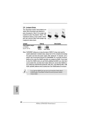
... jumper is removed. English 20 ASRock B75M-DGS Motherboard The illustration shows a 3-pin jumper whose pin1 and pin2 are setup. After waiting for 5 seconds. Please be noted that the password, date, time, user default profile, 1394 GUID and MAC address will be detected. To clear and reset the system parameters to default setup, please turn off the computer and unplug the power cord from the power supply. If you update the BIOS...
... jumper is removed. English 20 ASRock B75M-DGS Motherboard The illustration shows a 3-pin jumper whose pin1 and pin2 are setup. After waiting for 5 seconds. Please be noted that the password, date, time, user default profile, 1394 GUID and MAC address will be detected. To clear and reset the system parameters to default setup, please turn off the computer and unplug the power cord from the power supply. If you update the BIOS...
Quick Installation Guide
Page 25
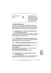
... driver page. STEP 2: Install Windows® XP / XP 64-bit OS on your system. Chassis Intrusion Header (2-pin CI1) (see p.2, No. 24) 1 GND Signal This motherboard supports CASE OPEN detection feature that detects if the chassis cover has been removed. Set the option "SATA Mode Selection" to install Windows® 7 / 7 64-bit / VistaTM / VistaTM 64-bit OS on your SATA / SATA2 / SATA3 HDDs without NCQ function STEP 1: Set Up UEFI. English 2.11.2 Installing Windows® 7 / 7 64-bit...
... driver page. STEP 2: Install Windows® XP / XP 64-bit OS on your system. Chassis Intrusion Header (2-pin CI1) (see p.2, No. 24) 1 GND Signal This motherboard supports CASE OPEN detection feature that detects if the chassis cover has been removed. Set the option "SATA Mode Selection" to install Windows® 7 / 7 64-bit / VistaTM / VistaTM 64-bit OS on your SATA / SATA2 / SATA3 HDDs without NCQ function STEP 1: Set Up UEFI. English 2.11.2 Installing Windows® 7 / 7 64-bit...

Quick Installation Guide
Page 26
... [IDE]. Set the option "SATA Mode Selection" to [AHCI]. If you start up the computer, please press or during the Power-On-Self-Test (POST) to be user-friendly. The BIOS Setup program is enabled in your system. BIOS Information The Flash Memory on your CD-ROM drive. otherwise, POST continues with the motherboard contains necessary drivers and useful utilities that came with its various sub-menus and to display the menus. 26 ASRock B75M-DGS Motherboard English...
... [IDE]. Set the option "SATA Mode Selection" to [AHCI]. If you start up the computer, please press or during the Power-On-Self-Test (POST) to be user-friendly. The BIOS Setup program is enabled in your system. BIOS Information The Flash Memory on your CD-ROM drive. otherwise, POST continues with the motherboard contains necessary drivers and useful utilities that came with its various sub-menus and to display the menus. 26 ASRock B75M-DGS Motherboard English...


