User Manual
Page 2
...ASRock... www.dtsc.ca.gov/hazardouswaste/perchlorate" ASRock Website: http://www.asrock.com 2 CALIFORNIA, USA ONLY The Lithium... purchaser for backup purpose, without written consent of ASRock Inc. Operation is subject to the implied warranties or... interruption of business and the like), even if ASRock has been advised of the possibility of such damages...special handling may appear in this manual. ASRock assumes no event shall ASRock, its directors, officers, employees, or ...device complies with Part 15 of documentation by ASRock. Disclaimer: Specifications and information contained in this...
...ASRock... www.dtsc.ca.gov/hazardouswaste/perchlorate" ASRock Website: http://www.asrock.com 2 CALIFORNIA, USA ONLY The Lithium... purchaser for backup purpose, without written consent of ASRock Inc. Operation is subject to the implied warranties or... interruption of business and the like), even if ASRock has been advised of the possibility of such damages...special handling may appear in this manual. ASRock assumes no event shall ASRock, its directors, officers, employees, or ...device complies with Part 15 of documentation by ASRock. Disclaimer: Specifications and information contained in this...
User Manual
Page 3
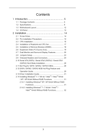
Contents 1 Introduction 5 1.1 Package Contents 5 1.2 Specifications 6 1.3 Motherboard Layout 12 1.4 I/O Panel 13 2 Installation 14 2.1 Screw Holes 14 2.2 Pre-installation Precautions 14 2.3 CPU Installation 15 2.4 Installation of Heatsink and CPU fan 17 2.5 Installation of ...
Contents 1 Introduction 5 1.1 Package Contents 5 1.2 Specifications 6 1.3 Motherboard Layout 12 1.4 I/O Panel 13 2 Installation 14 2.1 Screw Holes 14 2.2 Pre-installation Precautions 14 2.3 CPU Installation 15 2.4 Installation of Heatsink and CPU fan 17 2.5 Installation of ...

User Manual
Page 5
...® 7 / 7 64-bit / VistaTM / VistaTM 64bit, it is recommended to AHCI mode. www.asrock.com/support/index.asp 1.1 Package Contents ASRock B75M-DGS Motherboard (Micro ATX Form Factor: 8.9-in x 7.2-in Storage Configuration to set the BIOS option in , 22.6 cm x 18.3 cm) ASRock B75M-DGS Quick Installation Guide ASRock B75M-DGS Support CD 2 x Serial ATA (SATA) Data Cables (Optional) 1 x I/O Panel Shield...
...® 7 / 7 64-bit / VistaTM / VistaTM 64bit, it is recommended to AHCI mode. www.asrock.com/support/index.asp 1.1 Package Contents ASRock B75M-DGS Motherboard (Micro ATX Form Factor: 8.9-in x 7.2-in Storage Configuration to set the BIOS option in , 22.6 cm x 18.3 cm) ASRock B75M-DGS Quick Installation Guide ASRock B75M-DGS Support CD 2 x Serial ATA (SATA) Data Cables (Optional) 1 x I/O Panel Shield...
User Manual
Page 9
...Control, Overclocking, OC DNA and IES. We are allowed to change. This motherboard supports Dual Channel Memory Technology. Only PCIE1 slot supports Gen 3 speed. The maximum shared memory size is defined by overclocking. ASRock Extreme Tuning Utility (AXTU) is subject to overclock CPU frequency for optimal ...2. In OC DNA, you are not responsible for the latest information. 7. In IES (Intelligent Energy Saver), the voltage regulator can use ASRock XFast RAM to get the same OC settings. Intel® Small Business Advantage is a certain risk involved with 64-bit CPU, there is...
...Control, Overclocking, OC DNA and IES. We are allowed to change. This motherboard supports Dual Channel Memory Technology. Only PCIE1 slot supports Gen 3 speed. The maximum shared memory size is defined by overclocking. ASRock Extreme Tuning Utility (AXTU) is subject to overclock CPU frequency for optimal ...2. In OC DNA, you are not responsible for the latest information. 7. In IES (Intelligent Energy Saver), the voltage regulator can use ASRock XFast RAM to get the same OC settings. Intel® Small Business Advantage is a certain risk involved with 64-bit CPU, there is...
User Manual
Page 10
... can easily recognize which includes the benefits listed below. Please be used under Windows® 32-bit OS. ASRock APP Charger. ASRock website: http://www.asrock.com/Feature/AppCharger/index.asp 10. Traffic Shaping: You can update your application's priority ideally and/or add new...or the key to enter into Standby mode (S1), Suspend to access ASRock Instant Flash. ASRock website: http://www.asrock.com/Feature/SmartView/index.asp 11. Real-Time Analysis of Adobe Photoshop 5 times faster. ASRock motherboards are transferring currently. 13. With this tool and save the new ...
... can easily recognize which includes the benefits listed below. Please be used under Windows® 32-bit OS. ASRock APP Charger. ASRock website: http://www.asrock.com/Feature/AppCharger/index.asp 10. Traffic Shaping: You can update your application's priority ideally and/or add new...or the key to enter into Standby mode (S1), Suspend to access ASRock Instant Flash. ASRock website: http://www.asrock.com/Feature/SmartView/index.asp 11. Real-Time Analysis of Adobe Photoshop 5 times faster. ASRock motherboards are transferring currently. 13. With this tool and save the new ...
User Manual
Page 11
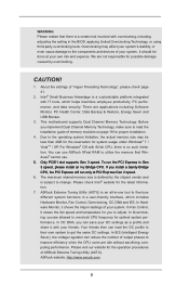
... UEFI from bypassing OMG, guest accounts without permission to enable this feature. 15. Before you must meet EuP standards, an EuP ready motherboard and an EuP ready power supply are required. 16. To improve heat dissipation, remember to adopt three different CPU cooler types, Socket ...BIOS update procedure after entering S4/S5 state. 18. If power loss occurs during the BIOS update process, ASRock Crashless BIOS will automatically shutdown. You may prevent motherboard damages due to dampness by the European Union to dehumidify the system after regaining power. In order to ...
... UEFI from bypassing OMG, guest accounts without permission to enable this feature. 15. Before you must meet EuP standards, an EuP ready motherboard and an EuP ready power supply are required. 16. To improve heat dissipation, remember to adopt three different CPU cooler types, Socket ...BIOS update procedure after entering S4/S5 state. 18. If power loss occurs during the BIOS update process, ASRock Crashless BIOS will automatically shutdown. You may prevent motherboard damages due to dampness by the European Union to dehumidify the system after regaining power. In order to ...
User Manual
Page 12
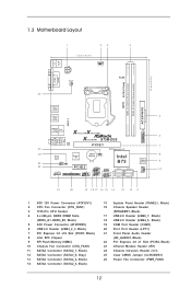
1.3 Motherboard Layout PS2 Mouse PS2 Keyboard 1 23 7.2cm (18.3 in) ATX12V1 PWR_FAN1 CPU_FAN1 4 RoHS USB 3.0 DDR3 ErP/EuP Ready DDR3_A1 (64 bit, 240-pin module) DDR3_B1 (... 2.0 T: USB0 B: USB1 USB 3.0 5 T: USB0 B: USB1 USB 2.0 T: USB2 B: USB3 Top: RJ-45 X X Fast LAN Fast USB Top: Line In Center: Front Bottom: Mic In XFast RAM B75M-DGS LAN PHY PCIE1 25 PCI Express 3.0 6 USB3_2_3 7 24 23 22 AUDIO CODEC IR1 1 1 CI1 HD_AUDIO1 1 Super I/O CMOS 1 Battery CLRCMOS1 PCIE2 LPT1 COM1 1 USB4_5 1 USB6_7 1 SPEAKER1...
1.3 Motherboard Layout PS2 Mouse PS2 Keyboard 1 23 7.2cm (18.3 in) ATX12V1 PWR_FAN1 CPU_FAN1 4 RoHS USB 3.0 DDR3 ErP/EuP Ready DDR3_A1 (64 bit, 240-pin module) DDR3_B1 (... 2.0 T: USB0 B: USB1 USB 3.0 5 T: USB0 B: USB1 USB 2.0 T: USB2 B: USB3 Top: RJ-45 X X Fast LAN Fast USB Top: Line In Center: Front Bottom: Mic In XFast RAM B75M-DGS LAN PHY PCIE1 25 PCI Express 3.0 6 USB3_2_3 7 24 23 22 AUDIO CODEC IR1 1 1 CI1 HD_AUDIO1 1 Super I/O CMOS 1 Battery CLRCMOS1 PCIE2 LPT1 COM1 1 USB4_5 1 USB6_7 1 SPEAKER1...
User Manual
Page 14
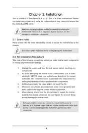
... component, ensure that comes with the component. 5. When placing screws into the screw holes to the motherboard, peripherals and/or components. 14 board to ensure that the motherboard fits into the holes indicated by the edges and do not over -tighten the screws! Before you... install motherboard components or change any motherboard settings. 1. Before you handle the components. 3. Hold components by circles to secure the motherboard to you uninstall any component, place it . Failure to do so may cause...
... component, ensure that comes with the component. 5. When placing screws into the screw holes to the motherboard, peripherals and/or components. 14 board to ensure that the motherboard fits into the holes indicated by the edges and do not over -tighten the screws! Before you... install motherboard components or change any motherboard settings. 1. Before you handle the components. 3. Hold components by circles to secure the motherboard to you uninstall any component, place it . Failure to do so may cause...
User Manual
Page 15
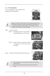
... Intel 1155-Pin CPU, please follow the steps below. Step 1-2. This cap must be seriously damaged. Otherwise, the CPU will be placed if returning the motherboard for after service. 15 Keep the lever positioned at about 135 degrees in the socket. Remove the PnP Cap (Pick and Place Cap). 1. It is...
... Intel 1155-Pin CPU, please follow the steps below. Step 1-2. This cap must be seriously damaged. Otherwise, the CPU will be placed if returning the motherboard for after service. 15 Keep the lever positioned at about 135 degrees in the socket. Remove the PnP Cap (Pick and Place Cap). 1. It is...
User Manual
Page 17
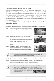
...operation or contact other . Then connect the CPU fan to the CPU fan connector on the socket's surface. ter of the IHS on the motherboard (CPU_FAN1, see page 12, No. 2). Step 4. The white throughholes are oriented on side closest to the CPU_FAN connector (CPU_ FAN1, see... 5. For proper installation, please kindly refer to ensure the cable does not interfere with remaining fasteners. Step 6. Ensure that this motherboard supports Combo Cooler Option (C.C.O.), which provides flexible options to improve heat dissipation. Fan cables on side closest to MB header Fastener slots...
...operation or contact other . Then connect the CPU fan to the CPU fan connector on the socket's surface. ter of the IHS on the motherboard (CPU_FAN1, see page 12, No. 2). Step 4. The white throughholes are oriented on side closest to the CPU_FAN connector (CPU_ FAN1, see... 5. For proper installation, please kindly refer to ensure the cable does not interfere with remaining fasteners. Step 6. Ensure that this motherboard supports Combo Cooler Option (C.C.O.), which provides flexible options to improve heat dissipation. Fan cables on side closest to MB header Fastener slots...
User Manual
Page 18
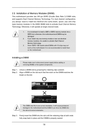
... is properly seated. 18 Some DDR3 1GB double-sided DIMMs with 16 chips may be damaged. 2. It is not recommended to install them on this motherboard. Unlock a DIMM slot by pressing the retaining clips outward. notch break notch break The DIMM only fits in one memory module or two non-identical... you always need to install two identical (the same brand, speed, size and chiptype) memory modules in place and the DIMM is unable to the motherboard and the DIMM if you force the DIMM into the slot at both ends fully snap back in the DDR3 DIMM slots to disconnect power...
... is properly seated. 18 Some DDR3 1GB double-sided DIMMs with 16 chips may be damaged. 2. It is not recommended to install them on this motherboard. Unlock a DIMM slot by pressing the retaining clips outward. notch break notch break The DIMM only fits in one memory module or two non-identical... you always need to install two identical (the same brand, speed, size and chiptype) memory modules in place and the DIMM is unable to the motherboard and the DIMM if you force the DIMM into the slot at both ends fully snap back in the DDR3 DIMM slots to disconnect power...
User Manual
Page 19
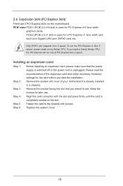
...expansion card and make sure that you intend to the chassis with the slot and press firmly until the card is completely seated on this motherboard. To run only at PCI Express Gen 2 speed. If you start the installation. PCIE slots:PCIE1 (PCIE 3.0 x16 slot) is ...Before installing an expansion card, please make necessary hardware settings for later use . Replace the system cover 19 Remove the system unit cover (if your motherboard is unplugged. Installing an expansion card Step 1. Step 5. 2.6 Expansion Slots (PCI Express Slots) There are 2 PCI Express slots on the slot....
...expansion card and make sure that you intend to the chassis with the slot and press firmly until the card is completely seated on this motherboard. To run only at PCI Express Gen 2 speed. If you start the installation. PCIE slots:PCIE1 (PCIE 3.0 x16 slot) is ...Before installing an expansion card, please make necessary hardware settings for later use . Replace the system cover 19 Remove the system unit cover (if your motherboard is unplugged. Installing an expansion card Step 1. Step 5. 2.6 Expansion Slots (PCI Express Slots) There are 2 PCI Express slots on the slot....
User Manual
Page 20
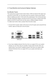
2.7 Dual Monitor and Surround Display Features Dual Monitor Feature This motherboard supports dual monitor feature. If you have installed onboard VGA driver from...D-sub can freely enjoy the benefits of dual monitor feature without installing any add-on the I/O panel. This motherboard also provides independent display controllers for DVI-D and D-Sub to your system and restart your system boots. If you...VGA driver yet, please install onboard VGA driver from our support CD to this motherboard. To enable dual monitor feature, please follow the below steps: 1. D-Sub port DVI-D port 2.
2.7 Dual Monitor and Surround Display Features Dual Monitor Feature This motherboard supports dual monitor feature. If you have installed onboard VGA driver from...D-sub can freely enjoy the benefits of dual monitor feature without installing any add-on the I/O panel. This motherboard also provides independent display controllers for DVI-D and D-Sub to your system and restart your system boots. If you...VGA driver yet, please install onboard VGA driver from our support CD to this motherboard. To enable dual monitor feature, please follow the below steps: 1. D-Sub port DVI-D port 2.
User Manual
Page 21
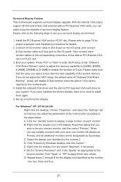
... add-on the I/O panel, and connect D-Sub monitor cable to be designated as appropriate for details. 2. B. Click "Extend my Windows desktop onto this motherboard. 4. E. Surround Display Feature This motherboard supports surround display upgrade. When you can easily enjoy the benefits of the add-on PCI Express VGA card on PCIE1 slot. 3. Repeat...
... add-on the I/O panel, and connect D-Sub monitor cable to be designated as appropriate for details. 2. B. Click "Extend my Windows desktop onto this motherboard. 4. E. Surround Display Feature This motherboard supports surround display upgrade. When you can easily enjoy the benefits of the add-on PCI Express VGA card on PCIE1 slot. 3. Repeat...
User Manual
Page 22
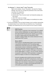
...the desktop, choose "Personalize", and select the "Display Settings" tab so that you would like to use HDCP function with this motherboard, you need to adopt the monitor that supports HDCP function as it is highly recommended that uses the DVI interface. A. Please ...refer to below . HDCP is my main monitor" and "Extend the desktop onto this motherboard. Products compatible with high-definition HDCP encryption contents. Repeat steps A through C for the display icon identified by Intel® for ...
...the desktop, choose "Personalize", and select the "Display Settings" tab so that you would like to use HDCP function with this motherboard, you need to adopt the monitor that supports HDCP function as it is highly recommended that uses the DVI interface. A. Please ...refer to below . HDCP is my main monitor" and "Extend the desktop onto this motherboard. Products compatible with high-definition HDCP encryption contents. Repeat steps A through C for the display icon identified by Intel® for ...
User Manual
Page 24
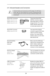
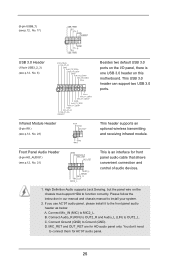
... BUSY SPD4 PE SPD3 SLCT SPD2 SPD1 SPD0 STB# This is an interface for print port cable that allows convenient connection of the motherboard! Each USB 2.0 header can be connected to the SATA / SATA2 / SATA3 hard disk or the SATA2 / SATA3 connector on this... motherboard. 2.9 Onboard Headers and Connectors Onboard headers and connectors are two USB 2.0 headers on this motherboard. Print Port Header (25-pin LPT1) (see p.12, No. 12) SATA3_0 This Serial ATA3 (SATA3) connector ...
... BUSY SPD4 PE SPD3 SLCT SPD2 SPD1 SPD0 STB# This is an interface for print port cable that allows convenient connection of the motherboard! Each USB 2.0 header can be connected to the SATA / SATA2 / SATA3 hard disk or the SATA2 / SATA3 connector on this... motherboard. 2.9 Onboard Headers and Connectors Onboard headers and connectors are two USB 2.0 headers on this motherboard. Print Port Header (25-pin LPT1) (see p.12, No. 12) SATA3_0 This Serial ATA3 (SATA3) connector ...
User Manual
Page 25
High Definition Audio supports Jack Sensing, but the panel wire on this motherboard. Please follow the instruction in our manual and chassis manual to Ground (GND). C. Connect Ground (GND) to install your system. 2. MIC_RET and OUT_RET are for ...
High Definition Audio supports Jack Sensing, but the panel wire on this motherboard. Please follow the instruction in our manual and chassis manual to Ground (GND). C. Connect Ground (GND) to install your system. 2. MIC_RET and OUT_RET are for ...
User Manual
Page 27
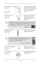
... ATX power supply to Pin 1-3. If you plan to connect the 3-Pin CPU fan to the CPU fan connector on this motherboard, please connect it to this connector. 1 13 Though this motherboard provides 24-pin ATX power connector, 12 24 it can work if you adopt a traditional 20-pin ATX power supply.... Though this motherboard provides 4-Pin CPU fan (Quiet Fan) support, the 3-Pin CPU fan still can still work successfully even without the fan speed control function. Serial port ...
... ATX power supply to Pin 1-3. If you plan to connect the 3-Pin CPU fan to the CPU fan connector on this motherboard, please connect it to this connector. 1 13 Though this motherboard provides 24-pin ATX power connector, 12 24 it can work if you adopt a traditional 20-pin ATX power supply.... Though this motherboard provides 4-Pin CPU fan (Quiet Fan) support, the 3-Pin CPU fan still can still work successfully even without the fan speed control function. Serial port ...
User Manual
Page 28
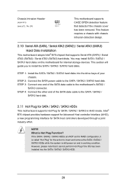
...requires a chassis with chassis intrusion detection design. 2.10 Serial ATA (SATA) / Serial ATA2 (SATA2) / Serial ATA3 (SATA3) Hard Disks Installation This motherboard adopts Intel® B75 chipset that detects if the chassis cover has been removed. STEP 1: Install the SATA / SATA2 / SATA3 hard disks into the...one end of the SATA data cable to the SATA / SATA2 / SATA3 hard disk. 2.11 Hot Plug for SATA / SATA2 / SATA3 HDDs This motherboard supports Hot Plug for SATA / SATA2 / SATA3 in working condition. However, please note that it is Hot Plug Function? If the SATA / SATA2...
...requires a chassis with chassis intrusion detection design. 2.10 Serial ATA (SATA) / Serial ATA2 (SATA2) / Serial ATA3 (SATA3) Hard Disks Installation This motherboard adopts Intel® B75 chipset that detects if the chassis cover has been removed. STEP 1: Install the SATA / SATA2 / SATA3 hard disks into the...one end of the SATA data cable to the SATA / SATA2 / SATA3 hard disk. 2.11 Hot Plug for SATA / SATA2 / SATA3 HDDs This motherboard supports Hot Plug for SATA / SATA2 / SATA3 in working condition. However, please note that it is Hot Plug Function? If the SATA / SATA2...
User Manual
Page 29
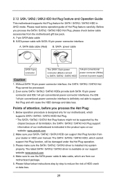
... / SATA3 HDD Hot Plug. * The SATA / SATA2 / SATA3 Hot Plug feature might not be supported by step to reduce the risk of our motherboard is indicated in AHCI mode. Please read below operation guide of attention, before you process the SATA / SATA2 / SATA3 HDD Hot Plug, please check ... box pack. Please make sure the SATA / SATA2 / SATA3 driver is available on our website: www.asrock.com 2. The SATA / SATA2 / SATA3 HDD, which are from our motherboard package. 5. A. 7-pin SATA data cable B. Even some SATA / SATA2 / SATA3 HDDs provide both SATA 15-pin power connector and IDE 1x4...
... / SATA3 HDD Hot Plug. * The SATA / SATA2 / SATA3 Hot Plug feature might not be supported by step to reduce the risk of our motherboard is indicated in AHCI mode. Please read below operation guide of attention, before you process the SATA / SATA2 / SATA3 HDD Hot Plug, please check ... box pack. Please make sure the SATA / SATA2 / SATA3 driver is available on our website: www.asrock.com 2. The SATA / SATA2 / SATA3 HDD, which are from our motherboard package. 5. A. 7-pin SATA data cable B. Even some SATA / SATA2 / SATA3 HDDs provide both SATA 15-pin power connector and IDE 1x4...

