User Manual
Page 2
... fitness for informational use only and subject to infringe. "Perchlorate Material-special handling may appear in this manual, ASRock does not provide warranty of ASRock Inc. CALIFORNIA, USA ONLY The Lithium battery adopted on this motherboard contains Perchlorate, a toxic substance controlled in Perchlorate Best Management Practices (BMP) regulations passed by the purchaser for...
... fitness for informational use only and subject to infringe. "Perchlorate Material-special handling may appear in this manual, ASRock does not provide warranty of ASRock Inc. CALIFORNIA, USA ONLY The Lithium battery adopted on this motherboard contains Perchlorate, a toxic substance controlled in Perchlorate Best Management Practices (BMP) regulations passed by the purchaser for...
User Manual
Page 3
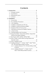
Contents 1 Introduction 5 1.1 Package Contents 5 1.2 Specifications 6 1.3 Motherboard Layout 12 1.4 I/O Panel 13 2 Installation 14 2.1 Screw Holes 14 2.2 Pre-installation Precautions 14 2.3 CPU Installation 15 2.4 Installation of Heatsink and CPU fan 17 2.5 Installation of ...
Contents 1 Introduction 5 1.1 Package Contents 5 1.2 Specifications 6 1.3 Motherboard Layout 12 1.4 I/O Panel 13 2 Installation 14 2.1 Screw Holes 14 2.2 Pre-installation Precautions 14 2.3 CPU Installation 15 2.4 Installation of Heatsink and CPU fan 17 2.5 Installation of ...

User Manual
Page 5
... the BIOS option in , 22.6 cm x 18.3 cm) ASRock B75M-DGS Quick Installation Guide ASRock B75M-DGS Support CD 2 x Serial ATA (SATA) Data Cables (Optional) 1 x I/O Panel Shield ASRock Reminds You... In this manual will be subject to the "User Manual" in our support CD for purchasing ASRock B75M-DGS motherboard, a reliable motherboard produced under ASRock's consistently stringent quality control. To get better performance...
... the BIOS option in , 22.6 cm x 18.3 cm) ASRock B75M-DGS Quick Installation Guide ASRock B75M-DGS Support CD 2 x Serial ATA (SATA) Data Cables (Optional) 1 x I/O Panel Shield ASRock Reminds You... In this manual will be subject to the "User Manual" in our support CD for purchasing ASRock B75M-DGS motherboard, a reliable motherboard produced under ASRock's consistently stringent quality control. To get better performance...
User Manual
Page 9
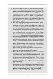
... 3 speed. In OC DNA, you can use . 5. Your friends then can reduce the number of ASRock Extreme Tuning Utility (AXTU). This motherboard supports Dual Channel Memory Technology. Please check Intel® website for the operation procedures of output phases to overclock... CPU frequency for proper installation. 4. ASRock website: http://www.asrock.com 9 For Windows® OS with IT tools, ...
... 3 speed. In OC DNA, you can use . 5. Your friends then can reduce the number of ASRock Extreme Tuning Utility (AXTU). This motherboard supports Dual Channel Memory Technology. Please check Intel® website for the operation procedures of output phases to overclock... CPU frequency for proper installation. 4. ASRock website: http://www.asrock.com 9 For Windows® OS with IT tools, ...
User Manual
Page 10
... Prioritization: You can easily recognize which includes the benefits listed below. Traffic Shaping: You can boost USB storage device performance. ASRock Instant Flash is the smart start page for IE that combines your most visited web sites, your history, your Facebook friends ...; 7 / 7 64 bit / VistaTM / VistaTM 64 bit, and your PC enters into ASRock Extreme Tuning Utility (AXTU). ASRock XFast USB can watch Youtube HD videos and download simultaneously. ASRock motherboards are transferring currently. 13. If you can update your Apple devices, such as iPhone/iPad/iPod...
... Prioritization: You can easily recognize which includes the benefits listed below. Traffic Shaping: You can boost USB storage device performance. ASRock Instant Flash is the smart start page for IE that combines your most visited web sites, your history, your Facebook friends ...; 7 / 7 64 bit / VistaTM / VistaTM 64 bit, and your PC enters into ASRock Extreme Tuning Utility (AXTU). ASRock XFast USB can watch Youtube HD videos and download simultaneously. ASRock motherboards are transferring currently. 13. If you can update your Apple devices, such as iPhone/iPad/iPod...
User Manual
Page 11
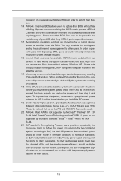
... of 5v, and the standby power efficiency should be running on the motherboard functions properly and unplug the power cord, then plug it back again. If power loss occurs during the BIOS update process, ASRock Crashless BIOS will power on automatically to dampness by the European Union to... spray thermal grease between the CPU and the heatsink when you must meet EuP standards, an EuP ready motherboard and an EuP ready power supply are not...
... of 5v, and the standby power efficiency should be running on the motherboard functions properly and unplug the power cord, then plug it back again. If power loss occurs during the BIOS update process, ASRock Crashless BIOS will power on automatically to dampness by the European Union to... spray thermal grease between the CPU and the heatsink when you must meet EuP standards, an EuP ready motherboard and an EuP ready power supply are not...
User Manual
Page 12
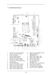
1.3 Motherboard Layout PS2 Mouse PS2 Keyboard 1 23 7.2cm (18.3 in) ATX12V1 PWR_FAN1 CPU_FAN1 4 RoHS USB 3.0 DDR3 ErP/EuP Ready DDR3_A1 (64 bit, 240-pin module) DDR3_B1 (... 2.0 T: USB0 B: USB1 USB 3.0 5 T: USB0 B: USB1 USB 2.0 T: USB2 B: USB3 Top: RJ-45 X X Fast LAN Fast USB Top: Line In Center: Front Bottom: Mic In XFast RAM B75M-DGS LAN PHY PCIE1 25 PCI Express 3.0 6 USB3_2_3 7 24 23 22 AUDIO CODEC IR1 1 1 CI1 HD_AUDIO1 1 Super I/O CMOS 1 Battery CLRCMOS1 PCIE2 LPT1 COM1 1 USB4_5 1 USB6_7 1 SPEAKER1...
1.3 Motherboard Layout PS2 Mouse PS2 Keyboard 1 23 7.2cm (18.3 in) ATX12V1 PWR_FAN1 CPU_FAN1 4 RoHS USB 3.0 DDR3 ErP/EuP Ready DDR3_A1 (64 bit, 240-pin module) DDR3_B1 (... 2.0 T: USB0 B: USB1 USB 3.0 5 T: USB0 B: USB1 USB 2.0 T: USB2 B: USB3 Top: RJ-45 X X Fast LAN Fast USB Top: Line In Center: Front Bottom: Mic In XFast RAM B75M-DGS LAN PHY PCIE1 25 PCI Express 3.0 6 USB3_2_3 7 24 23 22 AUDIO CODEC IR1 1 1 CI1 HD_AUDIO1 1 Super I/O CMOS 1 Battery CLRCMOS1 PCIE2 LPT1 COM1 1 USB4_5 1 USB6_7 1 SPEAKER1...
User Manual
Page 14
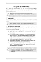
... on the carpet or the like. Failure to use a grounded wrist strap or touch a safety grounded object before you install motherboard components or change any motherboard settings. 1. Do not over -tighten the screws! Whenever you install or remove any component, ensure that the power is switched... This is detached from the wall socket before touching any component, place it . Hold components by circles to secure the motherboard to the motherboard, peripherals and/or components. 14 Make sure to static electricity, NEVER place your chassis to ensure that comes with the component. 5.
... on the carpet or the like. Failure to use a grounded wrist strap or touch a safety grounded object before you install motherboard components or change any motherboard settings. 1. Do not over -tighten the screws! Whenever you install or remove any component, ensure that the power is switched... This is detached from the wall socket before touching any component, place it . Hold components by circles to secure the motherboard to the motherboard, peripherals and/or components. 14 Make sure to static electricity, NEVER place your chassis to ensure that comes with the component. 5.
User Manual
Page 15
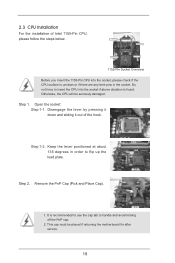
... installation of the hook. Open the socket: Step 1-1. Remove the PnP Cap (Pick and Place Cap). 1. Otherwise, the CPU will be placed if returning the motherboard for after service. 15
... installation of the hook. Open the socket: Step 1-1. Remove the PnP Cap (Pick and Place Cap). 1. Otherwise, the CPU will be placed if returning the motherboard for after service. 15
User Manual
Page 17
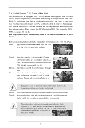
...fasteners with the CPU fan connector on side closest to the CPU_FAN connector (CPU_ FAN1, see page 12, No. 2). Fan cables on the motherboard. Then connect the CPU fan to MB header Fastener slots pointing straight out Press Down (4 Places) If you need to spray thermal interface ...material between the CPU and the heatsink to dissipate heat. Apply Thermal Interface Material Step 2. Step 3. Connect fan header with the motherboard throughholes. The white throughholes are oriented on fastener caps with thumb to ensure the cable does not interfere with tie-wrap to install ...
...fasteners with the CPU fan connector on side closest to the CPU_FAN connector (CPU_ FAN1, see page 12, No. 2). Fan cables on the motherboard. Then connect the CPU fan to MB header Fastener slots pointing straight out Press Down (4 Places) If you need to spray thermal interface ...material between the CPU and the heatsink to dissipate heat. Apply Thermal Interface Material Step 2. Step 3. Connect fan header with the motherboard throughholes. The white throughholes are oriented on fastener caps with thumb to ensure the cable does not interfere with tie-wrap to install ...
User Manual
Page 18
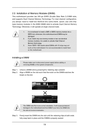
... with 16 chips may be damaged. 2. Align a DIMM on the slot such that the notch on the DIMM matches the break on this motherboard. Firmly insert the DIMM into the slot until the retaining clips at both ends fully snap back in place and the DIMM is not allowed... DIMM if you always need to install a DDR or DDR2 memory module into the slot at single channel mode. 1. otherwise, this motherboard and DIMM may not work on this motherboard. Unlock a DIMM slot by pressing the retaining clips outward. For dual channel configuration, you force the DIMM into a DDR3 slot;...
... with 16 chips may be damaged. 2. Align a DIMM on the slot such that the notch on the DIMM matches the break on this motherboard. Firmly insert the DIMM into the slot until the retaining clips at both ends fully snap back in place and the DIMM is not allowed... DIMM if you always need to install a DDR or DDR2 memory module into the slot at single channel mode. 1. otherwise, this motherboard and DIMM may not work on this motherboard. Unlock a DIMM slot by pressing the retaining clips outward. For dual channel configuration, you force the DIMM into a DDR3 slot;...
User Manual
Page 19
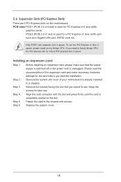
... connector with screws. 2.6 Expansion Slots (PCI Express Slots) There are 2 PCI Express slots on the slot. Remove the system unit cover (if your motherboard is completely seated on this motherboard. Keep the screws for a PCI Express x1 lane width card, such as a Gigabit LAN card, SATA2 card, etc. PCIE2 (PCIE 2.0 x1 slot...
... connector with screws. 2.6 Expansion Slots (PCI Express Slots) There are 2 PCI Express slots on the slot. Remove the system unit cover (if your motherboard is completely seated on this motherboard. Keep the screws for a PCI Express x1 lane width card, such as a Gigabit LAN card, SATA2 card, etc. PCIE2 (PCIE 2.0 x1 slot...
User Manual
Page 20
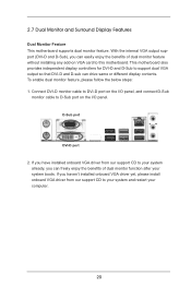
This motherboard also provides independent display controllers for DVI-D and D-Sub to your system already, you can freely enjoy the benefits of... D-Sub port on VGA card to your system and restart your system boots. 2.7 Dual Monitor and Surround Display Features Dual Monitor Feature This motherboard supports dual monitor feature. To enable dual monitor feature, please follow the below steps: 1. If you haven't installed onboard VGA driver yet,... 2. With the internal VGA output support (DVI-D and D-Sub), you have installed onboard VGA driver from our support CD to this motherboard.
This motherboard also provides independent display controllers for DVI-D and D-Sub to your system already, you can freely enjoy the benefits of... D-Sub port on VGA card to your system and restart your system boots. 2.7 Dual Monitor and Surround Display Features Dual Monitor Feature This motherboard supports dual monitor feature. To enable dual monitor feature, please follow the below steps: 1. If you haven't installed onboard VGA driver yet,... 2. With the internal VGA output support (DVI-D and D-Sub), you have installed onboard VGA driver from our support CD to this motherboard.
User Manual
Page 21
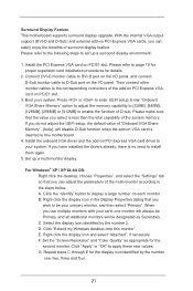
...VGA driver and the add-on PCI Express VGA card driver to set up a multi-monitor display. Click "Extend my Windows desktop onto this motherboard. 4. Set the "Screen Resolution" and "Color Quality" as Secondary. Please refer to be Primary, and all additional monitors will disable D-...to enter UEFI setup. Select the display icon identified by the number one monitor will always be your system. Surround Display Feature This motherboard supports surround display upgrade. Install the PCI Express VGA card on PCIE1 slot. 3. Then connect other monitor cables to the corresponding ...
...VGA driver and the add-on PCI Express VGA card driver to set up a multi-monitor display. Click "Extend my Windows desktop onto this motherboard. 4. Set the "Screen Resolution" and "Color Quality" as Secondary. Please refer to be Primary, and all additional monitors will disable D-...to enter UEFI setup. Select the display icon identified by the number one monitor will always be your system. Surround Display Feature This motherboard supports surround display upgrade. Install the PCI Express VGA card on PCIE1 slot. 3. Then connect other monitor cables to the corresponding ...
User Manual
Page 22
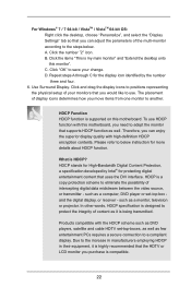
... monitor". Products compatible with high-definition HDCP encryption contents. Due to the increase in manufacturers employing HDCP in their equipment, it is supported on this motherboard, you need to adopt the monitor that supports HDCP function as a monitor, television or projector. Click the number "2" icon. To use . What is compatible....-top box and the digital display, or receiver - B. C. Click "OK" to save your monitors that you would like to use HDCP function with this motherboard. HDCP Function HDCP function is being transmitted. such as well.
... monitor". Products compatible with high-definition HDCP encryption contents. Due to the increase in manufacturers employing HDCP in their equipment, it is supported on this motherboard, you need to adopt the monitor that supports HDCP function as a monitor, television or projector. Click the number "2" icon. To use . What is compatible....-top box and the digital display, or receiver - B. C. Click "OK" to save your monitors that you would like to use HDCP function with this motherboard. HDCP Function HDCP function is being transmitted. such as well.
User Manual
Page 24
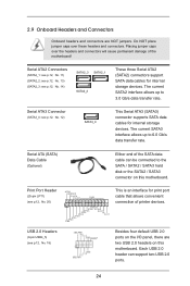
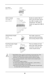
..., No. 14) SATA2_3 SATA2_1 SATA2_2 These three Serial ATA2 (SATA2) connectors support SATA data cables for print port cable that allows convenient connection of the motherboard! Print Port Header (25-pin LPT1) (see p.12, No. 18) Besides four default USB 2.0 ports on the I/O panel, there are NOT ...interface allows up to 3.0 Gb/s data transfer rate. 2.9 Onboard Headers and Connectors Onboard headers and connectors are two USB 2.0 headers on this motherboard. Each USB 2.0 header can be connected to the SATA / SATA2 / SATA3 hard disk or the SATA2 / SATA3 connector on this...
..., No. 14) SATA2_3 SATA2_1 SATA2_2 These three Serial ATA2 (SATA2) connectors support SATA data cables for print port cable that allows convenient connection of the motherboard! Print Port Header (25-pin LPT1) (see p.12, No. 18) Besides four default USB 2.0 ports on the I/O panel, there are NOT ...interface allows up to 3.0 Gb/s data transfer rate. 2.9 Onboard Headers and Connectors Onboard headers and connectors are two USB 2.0 headers on this motherboard. Each USB 2.0 header can be connected to the SATA / SATA2 / SATA3 hard disk or the SATA2 / SATA3 connector on this...
User Manual
Page 25
... (5-pin IR1) (see p.12, No. 6) IntA_P0_D+ IntA_P0_DGND IntA_P0_SSTX+ IntA_P0_SSTXGND IntA_P0_SSRX+ IntA_P0_SSRXVbus 1 Vbus IntA_P1_SSRXIntA_P1_SSRX+ GND IntA_P1_SSTXIntA_P1_SSTX+ GND IntA_P1_DIntA_P1_D+ DUMMY Besides two default USB 3.0 ports on this motherboard. Front Panel Audio Header (9-pin HD_AUDIO1) (see p.12, No. 21) GND PRESENCE# MIC_RET OUT_RET 1 OUT2_L J_SENSE OUT2_R MIC2_R MIC2_L This is one USB 3.0 header on...
... (5-pin IR1) (see p.12, No. 6) IntA_P0_D+ IntA_P0_DGND IntA_P0_SSTX+ IntA_P0_SSTXGND IntA_P0_SSRX+ IntA_P0_SSRXVbus 1 Vbus IntA_P1_SSRXIntA_P1_SSRX+ GND IntA_P1_SSTXIntA_P1_SSTX+ GND IntA_P1_DIntA_P1_D+ DUMMY Besides two default USB 3.0 ports on this motherboard. Front Panel Audio Header (9-pin HD_AUDIO1) (see p.12, No. 21) GND PRESENCE# MIC_RET OUT_RET 1 OUT2_L J_SENSE OUT2_R MIC2_R MIC2_L This is one USB 3.0 header on...
User Manual
Page 27
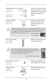
... connect it can work if you plan to connect the 3-Pin CPU fan to the CPU fan connector on this motherboard provides 24-pin ATX power connector, 12 24 it to the ground pin. Though this connector. Chassis and Power Fan Connectors (4-pin CHA_FAN1) ... Connector (4-pin ATX12V1) (see p.12, No. 2) GND 1 2 3 4 Please connect the CPU fan cable to the connector and match the black wire to this motherboard provides 4-Pin CPU fan (Quiet Fan) support, the 3-Pin CPU fan still can still work successfully even without the fan speed control function. CPU Fan...
... connect it can work if you plan to connect the 3-Pin CPU fan to the CPU fan connector on this motherboard provides 24-pin ATX power connector, 12 24 it to the ground pin. Though this connector. Chassis and Power Fan Connectors (4-pin CHA_FAN1) ... Connector (4-pin ATX12V1) (see p.12, No. 2) GND 1 2 3 4 Please connect the CPU fan cable to the connector and match the black wire to this motherboard provides 4-Pin CPU fan (Quiet Fan) support, the 3-Pin CPU fan still can still work successfully even without the fan speed control function. CPU Fan...
User Manual
Page 28
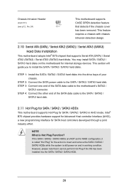
...hard disks into the SATA / SATA2 / SATA3 HDD. 28 Chassis Intrusion Header (2-pin CI1) (see p.12, No. 24) 1 GND Signal This motherboard supports CASE OPEN detection feature that supports Serial ATA (SATA) / Serial ATA2 (SATA2) / Serial ATA3 (SATA3) hard disks. This feature requires a chassis... and remove the SATA / SATA2 / SATA3 HDDs while the system is Hot Plug Function? This section will guide you to the motherboard's SATA2 / SATA3 connector. Intel® B75 chipset provides hardware support for Advanced Host controller Interface (AHCI), a new programming interface for...
...hard disks into the SATA / SATA2 / SATA3 HDD. 28 Chassis Intrusion Header (2-pin CI1) (see p.12, No. 24) 1 GND Signal This motherboard supports CASE OPEN detection feature that supports Serial ATA (SATA) / Serial ATA2 (SATA2) / Serial ATA3 (SATA3) hard disks. This feature requires a chassis... and remove the SATA / SATA2 / SATA3 HDDs while the system is Hot Plug Function? This section will guide you to the motherboard's SATA2 / SATA3 connector. Intel® B75 chipset provides hardware support for Advanced Host controller Interface (AHCI), a new programming interface for...
User Manual
Page 29
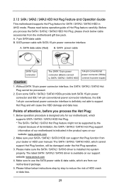
... system properly. SATA power cable with SATA 15-pin power connector interface A. The SATA / SATA2 / SATA3 HDD, which are from our motherboard package. 5. Please follow below instructions step by the chipset because of its limitation, the SATA / SATA2 / SATA3 Hot Plug support information of... 4. Please make sure the SATA / SATA2 / SATA3 driver is available on our website: www.asrock.com 2. A. 7-pin SATA data cable B. SATA data cable (Red) B. Points of our motherboard is indicated in AHCI mode. SATA power cable SATA 7-pin connector The SATA 15-pin power connector (Black) connect...
... system properly. SATA power cable with SATA 15-pin power connector interface A. The SATA / SATA2 / SATA3 HDD, which are from our motherboard package. 5. Please follow below instructions step by the chipset because of its limitation, the SATA / SATA2 / SATA3 Hot Plug support information of... 4. Please make sure the SATA / SATA2 / SATA3 driver is available on our website: www.asrock.com 2. A. 7-pin SATA data cable B. SATA data cable (Red) B. Points of our motherboard is indicated in AHCI mode. SATA power cable SATA 7-pin connector The SATA 15-pin power connector (Black) connect...

