User Manual
Page 2
...manual are used only for identification or explanation and to change without notice, and should not be constructed as a commitment by ASRock. CALIFORNIA, USA ONLY The Lithium battery adopted on this manual. When you discard the Lithium battery in California, USA, please... operation. With respect to the contents of this device must accept any interference received, including interference that may appear in this motherboard contains Perchlorate, a toxic substance controlled in Perchlorate Best Management Practices (BMP) regulations passed by the purchaser for backup purpose, ...
...manual are used only for identification or explanation and to change without notice, and should not be constructed as a commitment by ASRock. CALIFORNIA, USA ONLY The Lithium battery adopted on this manual. When you discard the Lithium battery in California, USA, please... operation. With respect to the contents of this device must accept any interference received, including interference that may appear in this motherboard contains Perchlorate, a toxic substance controlled in Perchlorate Best Management Practices (BMP) regulations passed by the purchaser for backup purpose, ...

User Manual
Page 3
... ATA (SATA) / Serial ATAII (SATAII) Hard Disks Installation 24 2.10 Hot Plug and Hot Swap Functions for Windows® VistaTM Premium 2007 and Basic Logo 9 1.4 Motherboard Layout 10 1.5 HD 8CH I/O Panel 11 2 .
... ATA (SATA) / Serial ATAII (SATAII) Hard Disks Installation 24 2.10 Hot Plug and Hot Swap Functions for Windows® VistaTM Premium 2007 and Basic Logo 9 1.4 Motherboard Layout 10 1.5 HD 8CH I/O Panel 11 2 .
User Manual
Page 5
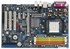
... and information of this manual occur, the updated version will be subject to quality and endurance. ASRock website http://www.asrock.com 1.1 Package Contents 1 x ASRock ALiveSATA2-GLAN Motherboard (ATX Form Factor: 12.0-in x 8.0-in, 30.5 cm x 20.3 cm) 1 x ASRock ALiveSATA2-GLAN Quick Installation Guide 1 x ASRock ALiveSATA2-GLAN Support CD 1 x Ultra ATA 66/100/133 IDE Ribbon Cable (80-conductor) 1 x 3.5-in Floppy Drive...
... and information of this manual occur, the updated version will be subject to quality and endurance. ASRock website http://www.asrock.com 1.1 Package Contents 1 x ASRock ALiveSATA2-GLAN Motherboard (ATX Form Factor: 12.0-in x 8.0-in, 30.5 cm x 20.3 cm) 1 x ASRock ALiveSATA2-GLAN Quick Installation Guide 1 x ASRock ALiveSATA2-GLAN Support CD 1 x Ultra ATA 66/100/133 IDE Ribbon Cable (80-conductor) 1 x 3.5-in Floppy Drive...
User Manual
Page 8
...automatically shutdown. Frequencies other than 4GB for the reservation for USB 2.0 works fine under Windows® XP and Windows® VistaTM. This motherboard supports ASRock AM2 Boost overclocking technology. However, we will improve up to 12.5%, but the effect still depends on the AM2 CPU you resume the system..., please check if the CPU fan on the motherboard functions properly and unplug the power cord, then plug it may not be ...
...automatically shutdown. Frequencies other than 4GB for the reservation for USB 2.0 works fine under Windows® XP and Windows® VistaTM. This motherboard supports ASRock AM2 Boost overclocking technology. However, we will improve up to 12.5%, but the effect still depends on the AM2 CPU you resume the system..., please check if the CPU fan on the motherboard functions properly and unplug the power cord, then plug it may not be ...

User Manual
Page 9
1.3 Minimum Hardware Requirement Table for Windows® VistaTM Premium 2007 and Basic Logo For system integrators and users who purchase this motherboard and plan to qualify for minimum hardware requirements. CPU Memory VGA Sempron 2800+ 1GB system memory DX9.0 with WDDM Driver with 128bit VGA memory (Premium) ...
1.3 Minimum Hardware Requirement Table for Windows® VistaTM Premium 2007 and Basic Logo For system integrators and users who purchase this motherboard and plan to qualify for minimum hardware requirements. CPU Memory VGA Sempron 2800+ 1GB system memory DX9.0 with WDDM Driver with 128bit VGA memory (Premium) ...
User Manual
Page 12
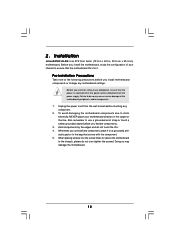
...5. Hold components by the edges and do so may damage the motherboard. 12 Whenever you install or remove any motherboard settings. Failure to do not touch the ICs. 4. Unplug the power cord from the power supply. Installation ALiveSATA2-GLAN is an ATX form factor (12.0-in x 8.0-in the bag... that the power is switched off or the power cord is detached from the wall socket before you install the motherboard, study the configuration of the following precautions before...
...5. Hold components by the edges and do so may damage the motherboard. 12 Whenever you install or remove any motherboard settings. Failure to do not touch the ICs. 4. Unplug the power cord from the power supply. Installation ALiveSATA2-GLAN is an ATX form factor (12.0-in x 8.0-in the bag... that the power is switched off or the power cord is detached from the wall socket before you install the motherboard, study the configuration of the following precautions before...
User Manual
Page 13
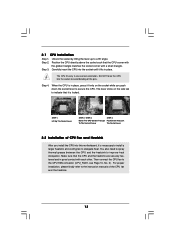
... Installation Step 1. When the CPU is in good contact with a small triangle. The lever clicks on the socket while you install the CPU into this motherboard, it is locked. Make sure that the CPU corner with the golden triangle matches the socket corner with each other. Then connect the CPU fan...
... Installation Step 1. When the CPU is in good contact with a small triangle. The lever clicks on the socket while you install the CPU into this motherboard, it is locked. Make sure that the CPU corner with the golden triangle matches the socket corner with each other. Then connect the CPU fan...
User Manual
Page 14
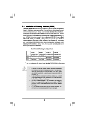
...the same color. In other words, install them in the DDRII DIMM slots on this motherboard and DIMM may refer to activate the Dual Channel Memory Technology. 3. otherwise, this motherboard, it is NOT installed in the same Dual Channel, for dual channel configuration, and ... Channel Memory Technology . 4. If only one memory module or three memory modules are installed in the slots of Memory Modules (DIMM) ALiveSATA2-GLAN motherboard provides four 240-pin DDRII (Double Data Rate II) DIMM slots, and supports Dual Channel Memory Technology. 2.3 Installation of the same ...
...the same color. In other words, install them in the DDRII DIMM slots on this motherboard and DIMM may refer to activate the Dual Channel Memory Technology. 3. otherwise, this motherboard, it is NOT installed in the same Dual Channel, for dual channel configuration, and ... Channel Memory Technology . 4. If only one memory module or three memory modules are installed in the slots of Memory Modules (DIMM) ALiveSATA2-GLAN motherboard provides four 240-pin DDRII (Double Data Rate II) DIMM slots, and supports Dual Channel Memory Technology. 2.3 Installation of the same ...
User Manual
Page 15
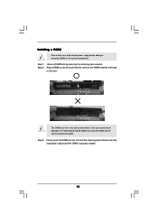
Installing a DIMM Please make sure to the motherboard and the DIMM if you force the DIMM into the slot until the retaining clips at incorrect orientation. Step 2. It will cause permanent damage to ...
Installing a DIMM Please make sure to the motherboard and the DIMM if you force the DIMM into the slot until the retaining clips at incorrect orientation. Step 2. It will cause permanent damage to ...
User Manual
Page 16
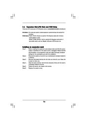
... PCI Express cards with x1 lane width cards, such as Gigabit LAN card, SATA2 card, etc. Remove the system unit cover (if your motherboard is completely seated on ALiveSATA2-GLAN motherboard. PCIE Slots: PCIE1 (PCIE x16 slot) is used to the chassis with the slot and press firmly until the card is already installed...
... PCI Express cards with x1 lane width cards, such as Gigabit LAN card, SATA2 card, etc. Remove the system unit cover (if your motherboard is completely seated on ALiveSATA2-GLAN motherboard. PCIE Slots: PCIE1 (PCIE x16 slot) is used to the chassis with the slot and press firmly until the card is already installed...
User Manual
Page 18
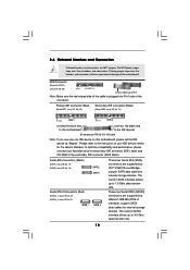
... the black end to the IDE devices 80-conductor ATA 66/100/133 cable Note: If you use only one IDE device on this motherboard, please set the IDE device as "Master". Besides, to 1.5 Gb/s data transfer rate. The current SATAII interface allows up to optimize compatibility and performance, please ... p.10, No. 13) Secondary IDE Connector (Black) (39-pin IDE2, see p.10, No. 22) Pin1 FLOPPY1 the red-striped side to the instruction of the motherboard! Please refer to Pin1 Note: Make sure the red-striped side of the cable is plugged into Pin1 side of the connector. The current SATA...
... the black end to the IDE devices 80-conductor ATA 66/100/133 cable Note: If you use only one IDE device on this motherboard, please set the IDE device as "Master". Besides, to 1.5 Gb/s data transfer rate. The current SATAII interface allows up to optimize compatibility and performance, please ... p.10, No. 13) Secondary IDE Connector (Black) (39-pin IDE2, see p.10, No. 22) Pin1 FLOPPY1 the red-striped side to the instruction of the motherboard! Please refer to Pin1 Note: Make sure the red-striped side of the cable is plugged into Pin1 side of the connector. The current SATA...
User Manual
Page 19
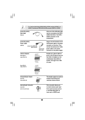
...) (CD1: see p.10 No. 10) USB_PWR P-7 P+7 GND DUMMY 1 GND P+6 P-6 USB_PWR Besides four default USB 2.0 ports on the I/O panel, there are two USB 2.0 headers on the motherboard. USB 2.0 Headers (9-pin USB6_7) (see p.10, No. 33) IRTX +5VSB DUMMY 1 GND IRRX CD-L GND GND CD-R CD1 This header supports an optional wireless transmitting... power cable to SATA connector (SATA1 or SATA2). This connector allows you to the SATA / SATAII hard disk or the SATA / SATAII connector on this motherboard.
...) (CD1: see p.10 No. 10) USB_PWR P-7 P+7 GND DUMMY 1 GND P+6 P-6 USB_PWR Besides four default USB 2.0 ports on the I/O panel, there are two USB 2.0 headers on the motherboard. USB 2.0 Headers (9-pin USB6_7) (see p.10, No. 33) IRTX +5VSB DUMMY 1 GND IRRX CD-L GND GND CD-R CD1 This header supports an optional wireless transmitting... power cable to SATA connector (SATA1 or SATA2). This connector allows you to the SATA / SATAII hard disk or the SATA / SATAII connector on this motherboard.
User Manual
Page 21
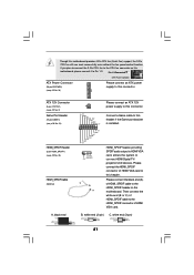
...) (see p.10 No. 34) Please connect an ATX power supply to this connector. Please connect the HDMI_SPDIF connector of HDMI_SPDIF cable to this motherboard provides 4-Pin CPU fan (Quiet Fan) support, the 3-Pin CPU fan still can work successfully even without the fan speed control function. Please connect... 1 +5V JAB2 JAY GND GND JAX JAB1 +5V 1 GND +5V SPDIFOUT C B A Connect a Game cable to this motherboard, please connect it to the CPU fan connector on the motherboard. white end (3-pin) +5V SPDIFOUT GND blue black SPDIFOUT GND blue black SPDIFOUT GND blue black 21 If you plan...
...) (see p.10 No. 34) Please connect an ATX power supply to this connector. Please connect the HDMI_SPDIF connector of HDMI_SPDIF cable to this motherboard provides 4-Pin CPU fan (Quiet Fan) support, the 3-Pin CPU fan still can work successfully even without the fan speed control function. Please connect... 1 +5V JAB2 JAY GND GND JAX JAB1 +5V 1 GND +5V SPDIFOUT C B A Connect a Game cable to this motherboard, please connect it to the CPU fan connector on the motherboard. white end (3-pin) +5V SPDIFOUT GND blue black SPDIFOUT GND blue black SPDIFOUT GND blue black 21 If you plan...
User Manual
Page 22
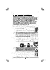
... HDMI VGA card to the HDMI_SPDIF connector of HDMI VGA card vendor. Make sure to correctly connect the HDMI_SPDIF cable to the motherboard and the HDMI VGA card according to your system. 22 Incorrect connection may be damaged. Connect the white end (B or C)...Connection Guide HDMI (High-Definition Multi-media Interface) is equipped with a HDMI_SPDIF header. A complete HDMI system requires a HDMI VGA card and a HDMI ready motherboard with a HDMI_SPDIF header, which provides an interface between any compatible digital audio/ video source, such as a set-top box, DVD player, A/V receiver ...
... HDMI VGA card to the HDMI_SPDIF connector of HDMI VGA card vendor. Make sure to correctly connect the HDMI_SPDIF cable to the motherboard and the HDMI VGA card according to your system. 22 Incorrect connection may be damaged. Connect the white end (B or C)...Connection Guide HDMI (High-Definition Multi-media Interface) is equipped with a HDMI_SPDIF header. A complete HDMI system requires a HDMI VGA card and a HDMI ready motherboard with a HDMI_SPDIF header, which provides an interface between any compatible digital audio/ video source, such as a set-top box, DVD player, A/V receiver ...
User Manual
Page 24
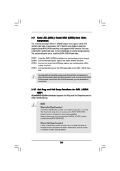
...system is called "Hot Plug" for the action to create RAID. 2.10 Hot Plug and Hot Swap Functions for SATA / SATAII HDDs ALiveSATA2-GLAN motherboard supports Hot Plug and Hot Swap functions for internal storage devices. You may install SATA / SATAII hard disks on and in working condition.... 2.9 Serial ATA (SATA) / Serial ATAII (SATAII) Hard Disks Installation This motherboard adopts JMicron® JMB363 chipset that supports Serial ATA (SATA) hard disks, and supports RAID functions. What is Hot Plug Function? This section...
...system is called "Hot Plug" for the action to create RAID. 2.10 Hot Plug and Hot Swap Functions for SATA / SATAII HDDs ALiveSATA2-GLAN motherboard supports Hot Plug and Hot Swap functions for internal storage devices. You may install SATA / SATAII hard disks on and in working condition.... 2.9 Serial ATA (SATA) / Serial ATAII (SATAII) Hard Disks Installation This motherboard adopts JMicron® JMB363 chipset that supports Serial ATA (SATA) hard disks, and supports RAID functions. What is Hot Plug Function? This section...
User Manual
Page 29
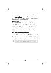
... RAID functions, please set the "SATA Operation Mode" option to install Windows® VistaTM / VistaTM 64-bit on your system. 2.14 Untied Overclocking Technology This motherboard supports Untied Overclocking Technology, which will show you apply Untied Overclocking Technology. 29 If you plan to install Windows® VistaTM / VistaTM 64-bit on...
... RAID functions, please set the "SATA Operation Mode" option to install Windows® VistaTM / VistaTM 64-bit on your system. 2.14 Untied Overclocking Technology This motherboard supports Untied Overclocking Technology, which will show you apply Untied Overclocking Technology. 29 If you plan to install Windows® VistaTM / VistaTM 64-bit on...
User Manual
Page 30
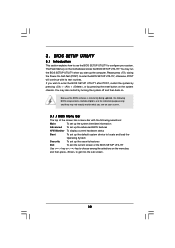
... press to enter the BIOS SETUP UTILITY after POST, restart the system by pressing + + , or by turning the system off and then back on the motherboard stores the BIOS SETUP UTILITY. Because the BIOS software is constantly being updated, the following BIOS setup screens and descriptions are for reference purpose only...
... press to enter the BIOS SETUP UTILITY after POST, restart the system by pressing + + , or by turning the system off and then back on the motherboard stores the BIOS SETUP UTILITY. Because the BIOS software is constantly being updated, the following BIOS setup screens and descriptions are for reference purpose only...
User Manual
Page 34
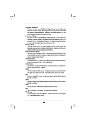
otherwise, it is set to [Manual]; The range of the value depends on the CPU you adopt on this motherboard. Configuration options: [Auto], [Single Channel]. It will allow better tolerance for system stability, it is set to [Enabled]. Configuration options: [Auto], [3CLK], [4CLK], [5CLK],... (DDRII 667)], and [400MHz (DDRII 800)]. Memory Channel Mode This item is set one of the value depends on the CPU you adopt on this motherboard. CAS Latency Use this to [Auto] by the code using [Auto]. Configuration options: [Auto], [3T], [4T], and [5T]. You can set to adjust...
otherwise, it is set to [Manual]; The range of the value depends on the CPU you adopt on this motherboard. Configuration options: [Auto], [Single Channel]. It will allow better tolerance for system stability, it is set to [Enabled]. Configuration options: [Auto], [3CLK], [4CLK], [5CLK],... (DDRII 667)], and [400MHz (DDRII 800)]. Memory Channel Mode This item is set one of the value depends on the CPU you adopt on this motherboard. CAS Latency Use this to [Auto] by the code using [Auto]. Configuration options: [Auto], [3T], [4T], and [5T]. You can set to adjust...
User Manual
Page 44
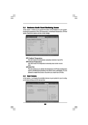
... fan. 3.5 Boot Screen In this section, it will display the available devices on your system for you to identify the temperature of the CPU temperature, motherboard temperature, CPU fan speed, chassis fan speed, and the critical voltage. The default value is [Disabled]. 3.4 Hardware Health Event Monitoring Screen In this section, it...
... fan. 3.5 Boot Screen In this section, it will display the available devices on your system for you to identify the temperature of the CPU temperature, motherboard temperature, CPU fan speed, chassis fan speed, and the critical voltage. The default value is [Disabled]. 3.4 Hardware Health Event Monitoring Screen In this section, it...
User Manual
Page 47
...Drivers Menu The Drivers Menu shows the available devices drivers if the system detects the installed devices. Software Support 4.1 Install Operating System This motherboard supports various Microsoft® Windows® operating systems: 2000 / XP / XP Media Center / XP 64-bit / VistaTM / VistaTM...information. 47 or you need to contact ASRock or want to know more information. 4.2 Support CD Information The Support CD that came with the motherboard contains necessary drivers and useful utilities that the motherboard supports. Because motherboard settings and hardware options vary, use ...
...Drivers Menu The Drivers Menu shows the available devices drivers if the system detects the installed devices. Software Support 4.1 Install Operating System This motherboard supports various Microsoft® Windows® operating systems: 2000 / XP / XP Media Center / XP 64-bit / VistaTM / VistaTM...information. 47 or you need to contact ASRock or want to know more information. 4.2 Support CD Information The Support CD that came with the motherboard contains necessary drivers and useful utilities that the motherboard supports. Because motherboard settings and hardware options vary, use ...


