Getting Started Guide
Page 3
...Placing Units On Top of Software Features 13 Switch 4400 - CONTENTS ABOUT THIS GUIDE Conventions 8 Related Documentation 9 Accessing Online Documentation 9 Product Registration 10 Documentation Comments 10 1 INTRODUCING THE SUPERSTACK 3 SWITCH 4400 About the Switch 4400 12 Summary of Hardware Features 12 Summary of... Each Other 25 Stacking Units 25 The Power-up Sequence 26 Powering-up the Switch 4400 26 Front View Detail 14 10BASE-T/ 100BASE...
...Placing Units On Top of Software Features 13 Switch 4400 - CONTENTS ABOUT THIS GUIDE Conventions 8 Related Documentation 9 Accessing Online Documentation 9 Product Registration 10 Documentation Comments 10 1 INTRODUCING THE SUPERSTACK 3 SWITCH 4400 About the Switch 4400 12 Summary of Hardware Features 12 Summary of... Each Other 25 Stacking Units 25 The Power-up Sequence 26 Powering-up the Switch 4400 26 Front View Detail 14 10BASE-T/ 100BASE...
Getting Started Guide
Page 4
... Power System 27 Choosing the Correct Cables 27 3 SETTING UP FOR MANAGEMENT Setting Up Overview 30 IP Configuration 30 Preparing for Management 32 Initial Switch Setup 32 Manual Setup 33 Connecting to a Front Panel Port 33 Connecting to the Console Port 35 Automatic Setup 38 Using... 3Com Network Supervisor 38 Connecting to the Console Port 38 Methods of Managing a Switch 41 Command Line Interface Management 41 Web Interface Management 42 SNMP Management 42 Setting Up Command Line Interface ...
... Power System 27 Choosing the Correct Cables 27 3 SETTING UP FOR MANAGEMENT Setting Up Overview 30 IP Configuration 30 Preparing for Management 32 Initial Switch Setup 32 Manual Setup 33 Connecting to a Front Panel Port 33 Connecting to the Console Port 35 Automatic Setup 38 Using... 3Com Network Supervisor 38 Connecting to the Console Port 38 Methods of Managing a Switch 41 Command Line Interface Management 41 Web Interface Management 42 SNMP Management 42 Setting Up Command Line Interface ...
Getting Started Guide
Page 5
A SAFETY INFORMATION Important Safety Information 54 L'information de Sécurité Importante 55 Wichtige Sicherheitsinformationen 57 B PIN-OUTS Null Modem Cable 59 PC-AT Serial Cable 59 Modem Cable 60 RJ-45 Pin Assignments 60 C TECHNICAL SPECIFICATIONS Switch 4400 (24-port) 63 Switch 4400 (48-port) 65 D TECHNICAL SUPPORT Online Technical Services 67 World Wide Web Site 67 3Com Knowledgebase Web Services 67 3Com FTP Site 68 Support from Your Network Supplier 68 Support from 3Com 68 Returning Products for Repair 70 INDEX REGULATORY NOTICES
A SAFETY INFORMATION Important Safety Information 54 L'information de Sécurité Importante 55 Wichtige Sicherheitsinformationen 57 B PIN-OUTS Null Modem Cable 59 PC-AT Serial Cable 59 Modem Cable 60 RJ-45 Pin Assignments 60 C TECHNICAL SPECIFICATIONS Switch 4400 (24-port) 63 Switch 4400 (48-port) 65 D TECHNICAL SUPPORT Online Technical Services 67 World Wide Web Site 67 3Com Knowledgebase Web Services 67 3Com FTP Site 68 Support from Your Network Supplier 68 Support from 3Com 68 Returning Products for Repair 70 INDEX REGULATORY NOTICES
Getting Started Guide
Page 7
... from the information in this guide apply to install and use by network administrators who are shipped with Switch 4400 models: ■ 3C17203 and 3C17206 - 24 10BASE-T/100BASE-TX ports ■ 3C17204 - 48 10BASE-T/100BASE-TX ports All procedures... described in this guide, follow the instructions in Adobe Acrobat Reader Portable Document Format (PDF) or HTML on the 3Com World Wide Web site: http://www.3com.com/ This guide is intended for use a SuperStack® 3 Switch 4400...
... from the information in this guide apply to install and use by network administrators who are shipped with Switch 4400 models: ■ 3C17203 and 3C17206 - 24 10BASE-T/100BASE-TX ports ■ 3C17204 - 48 10BASE-T/100BASE-TX ports All procedures... described in this guide, follow the instructions in Adobe Acrobat Reader Portable Document Format (PDF) or HTML on the 3Com World Wide Web site: http://www.3com.com/ This guide is intended for use a SuperStack® 3 Switch 4400...
Getting Started Guide
Page 9
...Related Documentation 9 Related Documentation In addition to this guide, each Switch documentation set includes the following online Documentation documentation: ■ SuperStack 3 Switch Implementation Guide (PDF format) ■ SuperStack 3 Switch Management Interface Reference Guide (HTML format). 1 To access the... ■ Documentation accompanying the Expansion Modules. ■ Documentation accompanying 3Com Network Supervisor. This is supplied in PDF format on the features supported by your Switch and how they can be displayed automatically. 2 Select the Documentation ...
...Related Documentation 9 Related Documentation In addition to this guide, each Switch documentation set includes the following online Documentation documentation: ■ SuperStack 3 Switch Implementation Guide (PDF format) ■ SuperStack 3 Switch Management Interface Reference Guide (HTML format). 1 To access the... ■ Documentation accompanying the Expansion Modules. ■ Documentation accompanying 3Com Network Supervisor. This is supplied in PDF format on the features supported by your Switch and how they can be displayed automatically. 2 Select the Documentation ...
Getting Started Guide
Page 10
...the Docs/reference directory on the title page) ■ Page number (if appropriate) Example: Part Number DUA 1720-3AAA0x SuperStack 3 Switch 4400 Getting Started Guide Page 21 Please e-mail comments about this document to us. They will need to access the CD-ROM...whole to maintain the structure of the CD-ROM. 3Com recommends that you . You can register your SuperStack 3 Switch 4400 on the 3Com Web site: http://support.3com.com/registration/frontpg.pl Your suggestions are very important to 3Com at: pddtechpubs_comments@3com.com Please include the following information when commenting: ...
...the Docs/reference directory on the title page) ■ Page number (if appropriate) Example: Part Number DUA 1720-3AAA0x SuperStack 3 Switch 4400 Getting Started Guide Page 21 Please e-mail comments about this document to us. They will need to access the CD-ROM...whole to maintain the structure of the CD-ROM. 3Com recommends that you . You can register your SuperStack 3 Switch 4400 on the 3Com Web site: http://support.3com.com/registration/frontpg.pl Your suggestions are very important to 3Com at: pddtechpubs_comments@3com.com Please include the following information when commenting: ...
Getting Started Guide
Page 11
It covers summaries of hardware and software features and also the following topics: ■ About the Switch 4400 ■ Switch 4400 - Rear View Detail ■ Default Settings 1 INTRODUCING THE SUPERSTACK 3 SWITCH 4400 This chapter contains introductory information about the Switch 4400 and how it can be used in your network. Front View Detail ■ Switch 4400 -
It covers summaries of hardware and software features and also the following topics: ■ About the Switch 4400 ■ Switch 4400 - Rear View Detail ■ Default Settings 1 INTRODUCING THE SUPERSTACK 3 SWITCH 4400 This chapter contains introductory information about the Switch 4400 and how it can be used in your network. Front View Detail ■ Switch 4400 -
Getting Started Guide
Page 12
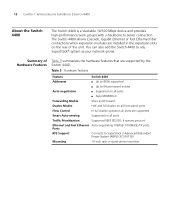
... Summary of the unit. You can also add the Switch 4400 to server connection. 12 CHAPTER 1: INTRODUCING THE SUPERSTACK 3 SWITCH 4400 About the Switch 4400 The Switch 4400 is a stackable 10/100 Mbps device and provides high-performance work groups with a backbone to any SuperStack® system as your network grows. The Switch 4400 allows Cascade, Gigabit Ethernet or Fast Ethernet Fiber...
... Summary of the unit. You can also add the Switch 4400 to server connection. 12 CHAPTER 1: INTRODUCING THE SUPERSTACK 3 SWITCH 4400 About the Switch 4400 The Switch 4400 is a stackable 10/100 Mbps device and provides high-performance work groups with a backbone to any SuperStack® system as your network grows. The Switch 4400 allows Cascade, Gigabit Ethernet or Fast Ethernet Fiber...
Getting Started Guide
Page 13
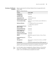
... Rapid Spanning Tree Protocol (802.1w) Webcache Support Quality of Service (QoS) RMON Email Notification of Events Management Port Security Switch 4400 Supported Supported Supported stack-wide Supported Support for up to 60 VLANs using the IEEE 802.1Q standard ■ 128 Multicast... 4 summarizes the software features that are not available on the SuperStack 3 Switch 4400 SE unless the product has been upgraded to the "SuperStack 3 Switch Management Interface Reference Guide" on the CD-ROM that accompanies the Switch. About the Switch 4400 13 Summary of Service (QoS) are supported by the...
... Rapid Spanning Tree Protocol (802.1w) Webcache Support Quality of Service (QoS) RMON Email Notification of Events Management Port Security Switch 4400 Supported Supported Supported stack-wide Supported Support for up to 60 VLANs using the IEEE 802.1Q standard ■ 128 Multicast... 4 summarizes the software features that are not available on the SuperStack 3 Switch 4400 SE unless the product has been upgraded to the "SuperStack 3 Switch Management Interface Reference Guide" on the CD-ROM that accompanies the Switch. About the Switch 4400 13 Summary of Service (QoS) are supported by the...
Getting Started Guide
Page 14
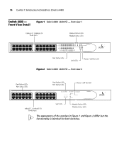
front view 2 The appearance of the overlays in Figure 1 and Figure 2 differ but the functionality is identical for both Switches. front view 1 Figure 2 Switch 4400 / 4400 SE - Front View Detail Figure 1 Switch 4400 / 4400 SE - 14 CHAPTER 1: INTRODUCING THE SUPERSTACK 3 SWITCH 4400 Switch 4400 -
front view 2 The appearance of the overlays in Figure 1 and Figure 2 differ but the functionality is identical for both Switches. front view 1 Figure 2 Switch 4400 / 4400 SE - Front View Detail Figure 1 Switch 4400 / 4400 SE - 14 CHAPTER 1: INTRODUCING THE SUPERSTACK 3 SWITCH 4400 Switch 4400 -
Getting Started Guide
Page 15
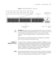
Switch 4400 - These are shielded RJ-45 data sockets. The maximum segment length is 100 m (328 ft) over ). Alternatively, you can be used as Auto MDIX (cross-over Category 5 twisted pair cable. They cannot be connected to these data sockets. 10BASE-T/ 100BASE-TX Ports The Switch... using the LEDs for problem solving, see "Solving Problems Indicated by LEDs" on the front of the Switch, and how to read their status according to these ports to a traditional PBX or public telephone network....manually set these sockets. Front View Detail 15 Figure 3 Switch 4400 (48-port) -
Switch 4400 - These are shielded RJ-45 data sockets. The maximum segment length is 100 m (328 ft) over ). Alternatively, you can be used as Auto MDIX (cross-over Category 5 twisted pair cable. They cannot be connected to these data sockets. 10BASE-T/ 100BASE-TX Ports The Switch... using the LEDs for problem solving, see "Solving Problems Indicated by LEDs" on the front of the Switch, and how to read their status according to these ports to a traditional PBX or public telephone network....manually set these sockets. Front View Detail 15 Figure 3 Switch 4400 (48-port) -
Getting Started Guide
Page 16
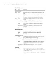
... and the port is disabled. The Link status has not been determined or there is present. Unit LEDs 1-8 Green When the Switch forms a stack with other Switch 4400 units, the LED indicates the position of a stack, LED 1 is on the port. Off No link is not supported. ... duplex packets are being transmitted/received on the port. Green flashing The Module is disabled. 16 CHAPTER 1: INTRODUCING THE SUPERSTACK 3 SWITCH 4400 Table 5 LED behavior LED Color Port Status LEDs Indicates Packet Green Yellow Full duplex packets are being transmitted/received on . When the...
... and the port is disabled. The Link status has not been determined or there is present. Unit LEDs 1-8 Green When the Switch forms a stack with other Switch 4400 units, the LED indicates the position of a stack, LED 1 is on the port. Off No link is not supported. ... duplex packets are being transmitted/received on the port. Green flashing The Module is disabled. 16 CHAPTER 1: INTRODUCING THE SUPERSTACK 3 SWITCH 4400 Table 5 LED behavior LED Color Port Status LEDs Indicates Packet Green Yellow Full duplex packets are being transmitted/received on . When the...
Getting Started Guide
Page 17
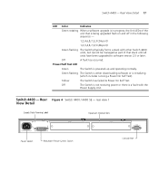
... with the Power Supply Unit. rear view 1 View Detail Rear Figure 4 Switch 4400 / 4400 SE - Switch 4400 - Power/Self Test LED Green The Switch is initializing (which includes running a Power On Self Test). Yellow The Switch has failed its Power On Self Test. Green flashing The Switch is either downloading software or is powered-up and operating normally...
... with the Power Supply Unit. rear view 1 View Detail Rear Figure 4 Switch 4400 / 4400 SE - Switch 4400 - Power/Self Test LED Green The Switch is initializing (which includes running a Power On Self Test). Yellow The Switch has failed its Power On Self Test. Green flashing The Switch is either downloading software or is powered-up and operating normally...
Getting Started Guide
Page 18
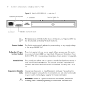
... this socket System Socket to connect a Switch 4400 to auto-baud, 8 data bits, no parity and 1 stop bit. See "Connecting a Redundant Power System" on page 27. 18 CHAPTER 1: INTRODUCING THE SUPERSTACK 3 SWITCH 4400 Figure 5 Switch 4400 / 4400 SE - The console port uses a... standard null modem cable and is fitted by tightening all screws with a suitable tool. Power Socket The Switch automatically adjusts its power setting to install Expansion...
... this socket System Socket to connect a Switch 4400 to auto-baud, 8 data bits, no parity and 1 stop bit. See "Connecting a Redundant Power System" on page 27. 18 CHAPTER 1: INTRODUCING THE SUPERSTACK 3 SWITCH 4400 Figure 5 Switch 4400 / 4400 SE - The console port uses a... standard null modem cable and is fitted by tightening all screws with a suitable tool. Power Socket The Switch automatically adjusts its power setting to install Expansion...
Getting Started Guide
Page 19
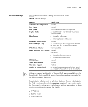
...Command Line Interface, the following settings are retained to allow you to connect to the 4400 enhanced feature set to "best effort" for the Switch 4400: Table 6 Default Settings Feature Switch 4400 Automatic IP Configuration Enabled Port Status Enabled Port Speed 10/100 Mbps ports are auto-negotiated... Rapid Spanning Tree Protocol Enabled Fast Start: ■ Enabled on front panel ports ■ Disabled on the SuperStack 3 Switch 4400 SE unless the product has been upgraded to and manage the Switch: ■ IP Address ■ Subnet Mask ■ Default Router All ports set .
...Command Line Interface, the following settings are retained to allow you to connect to the 4400 enhanced feature set to "best effort" for the Switch 4400: Table 6 Default Settings Feature Switch 4400 Automatic IP Configuration Enabled Port Status Enabled Port Speed 10/100 Mbps ports are auto-negotiated... Rapid Spanning Tree Protocol Enabled Fast Start: ■ Enabled on front panel ports ■ Disabled on the SuperStack 3 Switch 4400 SE unless the product has been upgraded to and manage the Switch: ■ IP Address ■ Subnet Mask ■ Default Router All ports set .

Getting Started Guide
Page 20
20 CHAPTER 1: INTRODUCING THE SUPERSTACK 3 SWITCH 4400
20 CHAPTER 1: INTRODUCING THE SUPERSTACK 3 SWITCH 4400

Getting Started Guide
Page 21
...Suitable Site ■ Rack-mounting ■ Placing Units On Top of this guide. Avant d'installer ou d'enlever tout composant du Switch 4400 ou d'entamer une procédure de maintenance, lisez les informations relatives à la sécurité qui se trouvent... dans l'Appendice A de ce guide. VORSICHT: Sicherheitsinformationen. Bevor Sie Komponenten aus dem Switch 4400 entfernen oder dem Switch 4400 hinzufuegen oder Instandhaltungsarbeiten verrichten, lesen Sie die Sicherheitsanweisungen, die in Appendix A (Anhang A) in Appendix A of Each Other...
...Suitable Site ■ Rack-mounting ■ Placing Units On Top of this guide. Avant d'installer ou d'enlever tout composant du Switch 4400 ou d'entamer une procédure de maintenance, lisez les informations relatives à la sécurité qui se trouvent... dans l'Appendice A de ce guide. VORSICHT: Sicherheitsinformationen. Bevor Sie Komponenten aus dem Switch 4400 entfernen oder dem Switch 4400 hinzufuegen oder Instandhaltungsarbeiten verrichten, lesen Sie die Sicherheitsanweisungen, die in Appendix A (Anhang A) in Appendix A of Each Other...
Getting Started Guide
Page 22
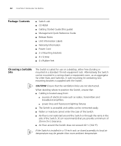
...9632; sources of electrical noise such as radios, transmitters and broadband amplifiers. ■ power lines and fluorescent lighting fixtures ■ The Switch is accessible and cables can be mounted in a wiring closet or equipment room, as an aggregator for use on a desktop, either...clearance. ■ Air flow around the Switch does not exceed 40 °C (104 °F). If the Switch is installed in the side of the Switch. 3Com recommends that the ventilation holes are not obstructed. 22 CHAPTER 2: INSTALLING THE SWITCH Package Contents ■ Switch unit ■ CD-ROM ■ ...
...9632; sources of electrical noise such as radios, transmitters and broadband amplifiers. ■ power lines and fluorescent lighting fixtures ■ The Switch is accessible and cables can be mounted in a wiring closet or equipment room, as an aggregator for use on a desktop, either...clearance. ■ Air flow around the Switch does not exceed 40 °C (104 °F). If the Switch is installed in the side of the Switch. 3Com recommends that the ventilation holes are not obstructed. 22 CHAPTER 2: INSTALLING THE SWITCH Package Contents ■ Switch unit ■ CD-ROM ■ ...

Getting Started Guide
Page 23
...high levels of AC noise, for example air conditioning units and laser printers. Remove all cables from the Switch before continuing. CAUTION: Disconnect all self adhesive pads from the underside of the Switch if they have been fitted. Rack-mounting 23 ■ The air is as free from dust as ...shown in a clean, air conditioned environment. ■ No more than eight Switch units are placed on top of one side of the Switch, as possible. ■ The unit is installed in Figure 6. Rack-mounting The Switch 4400 is 1U high and will fit in most standard 19-inch racks.
...high levels of AC noise, for example air conditioning units and laser printers. Remove all cables from the Switch before continuing. CAUTION: Disconnect all self adhesive pads from the underside of the Switch if they have been fitted. Rack-mounting 23 ■ The air is as free from dust as ...shown in a clean, air conditioned environment. ■ No more than eight Switch units are placed on top of one side of the Switch, as possible. ■ The unit is installed in Figure 6. Rack-mounting The Switch 4400 is 1U high and will fit in most standard 19-inch racks.

Getting Started Guide
Page 24
...The unit information label shows the following: ■ The 3Com product name of the Switch ■ The 3Com 3C number of the Switch ■ The unique MAC address (Ethernet address) of the Switch ■ The serial number of the Switch. 5 Insert the Switch into the 19-inch rack and secure with the mounting brackets... Damage caused to the unit by using incorrect screws invalidates your warranty. 4 Repeat steps 2 and 3 for the other side of the Switch You may need this information for rack-mounting 3 Insert the two screws and tighten with a suitable screwdriver. 24 CHAPTER 2: INSTALLING THE...
...The unit information label shows the following: ■ The 3Com product name of the Switch ■ The 3Com 3C number of the Switch ■ The unique MAC address (Ethernet address) of the Switch ■ The serial number of the Switch. 5 Insert the Switch into the 19-inch rack and secure with the mounting brackets... Damage caused to the unit by using incorrect screws invalidates your warranty. 4 Repeat steps 2 and 3 for the other side of the Switch You may need this information for rack-mounting 3 Insert the two screws and tighten with a suitable screwdriver. 24 CHAPTER 2: INSTALLING THE...


