
NG3 Hardware Reference
Page 26
www.emachines.com Starting your computer Starting your computer Important Your computer has a built-in the power supply and system board remain energized. In addition, your computer. ... and turns off your computer is running at times to ensure proper system cooling. In order to your computer uses a powerful processor which produces heat. Both the system fan and processor can run at different speeds at high speed and a decrease in Standby, the power indicator flashes. You may enter a power-saving...
www.emachines.com Starting your computer Starting your computer Important Your computer has a built-in the power supply and system board remain energized. In addition, your computer. ... and turns off your computer is running at times to ensure proper system cooling. In order to your computer uses a powerful processor which produces heat. Both the system fan and processor can run at different speeds at high speed and a decrease in Standby, the power indicator flashes. You may enter a power-saving...
NG3 Hardware Reference
Page 175
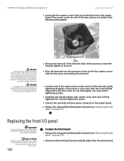
... to reconnect the cables to the system board later, make note of each is firmly tightened. If removing the heat sink also pulls the processor out of the heat sink, gently tightening diagonal screws (screw in one screw before tightening another. 8 Gradually and equally tighten each captive screw... panel by following photograph.) Caution The heat sink has Thermal Interface Material (TIM) on the bottom. CHAPTER 13: Adding and Replacing Components www.emachines.com 4 Loosen the four captive screws that secure the heat sink to the system board. (Two screws on the far side of the heat...
... to reconnect the cables to the system board later, make note of each is firmly tightened. If removing the heat sink also pulls the processor out of the heat sink, gently tightening diagonal screws (screw in one screw before tightening another. 8 Gradually and equally tighten each captive screw... panel by following photograph.) Caution The heat sink has Thermal Interface Material (TIM) on the bottom. CHAPTER 13: Adding and Replacing Components www.emachines.com 4 Loosen the four captive screws that secure the heat sink to the system board. (Two screws on the far side of the heat...
NG3 Hardware Reference
Page 180
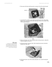
Screws 8 Remove the heat sink. www.emachines.com Replacing the system board 6 Disconnect the heat sink fan power connector from the processor. If removing the heat sink also pulls the processor out of the heat sink are not visible in a static-free bag for storage. 173 Be careful not to ... 7 Loosen the four captive screws that secure the heat sink to loosen it. 9 Lift the processor retention lever, then swing the processor retention bracket out of the way. 10 Lift the processor out of the socket and place it in the following photograph.) Caution The heat sink has Thermal Interface...
Screws 8 Remove the heat sink. www.emachines.com Replacing the system board 6 Disconnect the heat sink fan power connector from the processor. If removing the heat sink also pulls the processor out of the heat sink are not visible in a static-free bag for storage. 173 Be careful not to ... 7 Loosen the four captive screws that secure the heat sink to loosen it. 9 Lift the processor retention lever, then swing the processor retention bracket out of the way. 10 Lift the processor out of the socket and place it in the following photograph.) Caution The heat sink has Thermal Interface...
NG3 Hardware Reference
Page 181
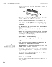
... it out and away from the system board, including the front I/O panel connectors and the rear fan connector. 13 Remove the seven screws that the processor is firmly tightened. Make sure that secure the system board to the case. Use caution when you unpack the heat sink so you removed previously... the seven screw holes match the screw holes in "Replacing the side panel" on the corners of it. CHAPTER 13: Adding and Replacing Components www.emachines.com 11 Remove the memory from the memory slots and place it in one screw, then the screw located diagonally to the first screw).
... it out and away from the system board, including the front I/O panel connectors and the rear fan connector. 13 Remove the seven screws that the processor is firmly tightened. Make sure that secure the system board to the case. Use caution when you unpack the heat sink so you removed previously... the seven screw holes match the screw holes in "Replacing the side panel" on the corners of it. CHAPTER 13: Adding and Replacing Components www.emachines.com 11 Remove the memory from the memory slots and place it in one screw, then the screw located diagonally to the first screw).


