
Support Guide
Page 2
Content General Application...5 Firmware Upgrade ...5 Using the Web Configurator 5 Using the Console Port 5 Using FTP:...6 Restore a Configuration File 6 Using the Web Configurator 6 Using the Console Port 7 Using FTP:...7 Backing Up a Configuration File 7 Using the Web Configurator 7 Using the Console Port 8 Using FTP:...9 Load Factory Defaults ...9 Using the Web Configurator 9 DHCP Relay per VLAN...11 DHCP Relay per VLAN...11 Scenario ...11 Triple Play ...16 Triple Play concept ...16 PPPoE service...16 Idea behind the PPPoE service 17 2
Content General Application...5 Firmware Upgrade ...5 Using the Web Configurator 5 Using the Console Port 5 Using FTP:...6 Restore a Configuration File 6 Using the Web Configurator 6 Using the Console Port 7 Using FTP:...7 Backing Up a Configuration File 7 Using the Web Configurator 7 Using the Console Port 8 Using FTP:...9 Load Factory Defaults ...9 Using the Web Configurator 9 DHCP Relay per VLAN...11 DHCP Relay per VLAN...11 Scenario ...11 Triple Play ...16 Triple Play concept ...16 PPPoE service...16 Idea behind the PPPoE service 17 2
Support Guide
Page 3
......29 VoIP Service ...33 1. VLAN Stacking configuration 38 2. Win RADIUS...27 Multicast Service ...28 1. Classifier configuration 35 3. Static VLAN configuration 40 3. Win RADIUS...22 VES-1616PE-54 configurations 24 1. VLAN configuration 24 P-870HW-51aV2 configurations 25 1. Interface Configuration 20 2. WAN configuration 25 2. ISP Info Setting Configuration 21 4. Policy Rule configuration 36 VLAN...
......29 VoIP Service ...33 1. VLAN Stacking configuration 38 2. Win RADIUS...27 Multicast Service ...28 1. Classifier configuration 35 3. Static VLAN configuration 40 3. Win RADIUS...22 VES-1616PE-54 configurations 24 1. VLAN configuration 24 P-870HW-51aV2 configurations 25 1. Interface Configuration 20 2. WAN configuration 25 2. ISP Info Setting Configuration 21 4. Policy Rule configuration 36 VLAN...
Support Guide
Page 4
VDSL Line Setup Configuration 47 FAQ...48 Frequently Asked Questions 48 1. How to check the current running firmware version 51 12. How do I enable MVR and IGMP snooping at the same time 52 4 What is the default setting of the Web Configurator 48 3. Scenario ...42 1. How to access my VES through the console port 48 4. VDSL Profile Configuration for Primary Template 43 2. What is "Dual-Personality interface" on the Web Configurator 50 10. What is default login password for console, telnet, and FTP 48 5. How to restart device from the Web Configurator 51 11....
VDSL Line Setup Configuration 47 FAQ...48 Frequently Asked Questions 48 1. How to check the current running firmware version 51 12. How do I enable MVR and IGMP snooping at the same time 52 4 What is the default setting of the Web Configurator 48 3. Scenario ...42 1. How to access my VES through the console port 48 4. VDSL Profile Configuration for Primary Template 43 2. What is "Dual-Personality interface" on the Web Configurator 50 10. What is default login password for console, telnet, and FTP 48 5. How to restart device from the Web Configurator 51 11....
Support Guide
Page 5
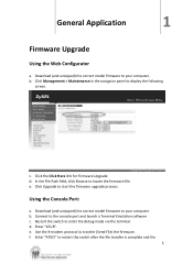
General Application 1 Firmware Upgrade Using the Web Configurator a. Download (and unzipped) the correct model firmware to your computer. Click the Click Here link for Firmware Upgrade d. e. Click Upgrade to locate the firmware file. Enter "ATUR". In the File Path field, click Browse to start the firmware upgrade process. b. Restart the switch to transfer (Send File) the firmware. c. d. Use the X-modem protocol to enter the debug mode via the terminal. Connect to restart the switch after the file transfer is complete and the 5 e. Enter "ATGO" to the console port ...
General Application 1 Firmware Upgrade Using the Web Configurator a. Download (and unzipped) the correct model firmware to your computer. Click the Click Here link for Firmware Upgrade d. e. Click Upgrade to locate the firmware file. Enter "ATUR". In the File Path field, click Browse to start the firmware upgrade process. b. Restart the switch to transfer (Send File) the firmware. c. d. Use the X-modem protocol to enter the debug mode via the terminal. Connect to restart the switch after the file transfer is complete and the 5 e. Enter "ATGO" to the console port ...
Support Guide
Page 6
b. d. Use "put" to "ras". Click the Click Here link for a user name. Download (and unzipped) the correct model firmware to your computer (firmware.bin) to the switch and renames it to transfer the firmware from the switch. Launch the FTP client on your computer. Enter the administrator login password to binary. Enter "bin" to set the transfer mode to access the switch and display FTP prompt. b. g. Enter "bye" to log out from the computer to the switch, for example: "put firmware.bin ras-0" (or ras-1) transfers the firmware on your computer to display the following ...
b. d. Use "put" to "ras". Click the Click Here link for a user name. Download (and unzipped) the correct model firmware to your computer (firmware.bin) to the switch and renames it to transfer the firmware from the switch. Launch the FTP client on your computer. Enter the administrator login password to binary. Enter "bin" to set the transfer mode to access the switch and display FTP prompt. b. g. Enter "bye" to log out from the computer to the switch, for example: "put firmware.bin ras-0" (or ras-1) transfers the firmware on your computer to display the following ...
Support Guide
Page 7
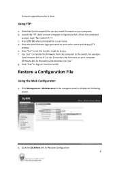
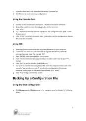
Connect to log out from the computer to the switch, for a user name d. c. Enter "bye" to the console port and launch a Terminal Emulation software. d. b. Using FTP: a. Enter "bin" to set the transfer mode to display the following screen. 7 g. Backing Up a Configuration File Using the Web Configurator: a. Click Management > Maintenance in the navigator panel to binary. c. Using the Console Port: a. c. Enter "ATGO" to "rom-0". Press [ENTER] when prompted for example: "put " to transfer the configuration file from the switch. Use "put comfig.rom rom-0" ...
Connect to log out from the computer to the switch, for a user name d. c. Enter "bye" to the console port and launch a Terminal Emulation software. d. b. Using FTP: a. Enter "bin" to set the transfer mode to display the following screen. 7 g. Backing Up a Configuration File Using the Web Configurator: a. Click Management > Maintenance in the navigator panel to binary. c. Using the Console Port: a. c. Enter "ATGO" to "rom-0". Press [ENTER] when prompted for example: "put " to transfer the configuration file from the switch. Use "put comfig.rom rom-0" ...
Support Guide
Page 8
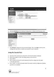
Click the Click Here link for Backup Configuration to a location you specify on your computer. Then, click Save to back up the configuration text file to display the following screen. Using the Console Port: a. b. c. d. Enter "ATGO" to display the File Download dialog. Click Backup to restart the switch after file transfer and the configuration backup processes are complete. 8 Restart the switch to transfer (Receive File) the configuration file (with a .rom file extension). e. Use X-modem protocol to enter the debug mode via the terminal. b. Enter "ATTD". ...
Click the Click Here link for Backup Configuration to a location you specify on your computer. Then, click Save to back up the configuration text file to display the following screen. Using the Console Port: a. b. c. d. Enter "ATGO" to display the File Download dialog. Click Backup to restart the switch after file transfer and the configuration backup processes are complete. 8 Restart the switch to transfer (Receive File) the configuration file (with a .rom file extension). e. Use X-modem protocol to enter the debug mode via the terminal. b. Enter "ATTD". ...
Support Guide
Page 9
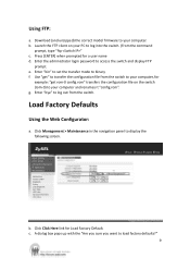
Enter "bin" to set the transfer mode to your computer and renames it "config.rom". b. Download (and unzipped) the correct model firmware to binary. e. Enter "bye" to display the following screen. Click Management > Maintenance in the navigation panel to log out from the switch to your computer, for example: "get rom-0 config.rom" transfers the configuration file on your PC to your computer. A dialog box pops up with the "Are you sure you want to access the switch and display FTP prompt. f. Load Factory Defaults Using the Web Configurator: a. g. c. Enter the ...
Enter "bin" to set the transfer mode to your computer and renames it "config.rom". b. Download (and unzipped) the correct model firmware to binary. e. Enter "bye" to display the following screen. Click Management > Maintenance in the navigation panel to log out from the switch to your computer, for example: "get rom-0 config.rom" transfers the configuration file on your PC to your computer. A dialog box pops up with the "Are you sure you want to access the switch and display FTP prompt. f. Load Factory Defaults Using the Web Configurator: a. g. c. Enter the ...
Support Guide
Page 10
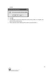
f. Click OK. e. Please note that the IP address of the switch is complete, the device automatically restarts. Click OK again to start the configuration reset process. d. prompt. After it is now 192.168.1.1. 10
f. Click OK. e. Please note that the IP address of the switch is complete, the device automatically restarts. Click OK again to start the configuration reset process. d. prompt. After it is now 192.168.1.1. 10
Support Guide
Page 11
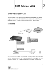
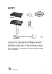
Scenario The purpose is 192.168.1.100, and tags a PVID=700 to the ingress traffic on the VES according to VLAN=700, to have a DHCP relay on port 1. The VES' In-band is to the DHCP server (IP=192.168.1.101). DHCP Relay per VLAN 2 DHCP Relay per VLAN The feature of DHCP relay per VLAN basis comes handy for managing the DHCP IP assignment to the DHCP server in the uplink Network. The NB shall receive the IP assigned from the DHCP server. 11 VES-1616PE-54 has the ability to relay the DHCP request packets according to its VLAN tag to the clients.
Scenario The purpose is 192.168.1.100, and tags a PVID=700 to the ingress traffic on the VES according to VLAN=700, to have a DHCP relay on port 1. The VES' In-band is to the DHCP server (IP=192.168.1.101). DHCP Relay per VLAN 2 DHCP Relay per VLAN The feature of DHCP relay per VLAN basis comes handy for managing the DHCP IP assignment to the DHCP server in the uplink Network. The NB shall receive the IP assigned from the DHCP server. 11 VES-1616PE-54 has the ability to relay the DHCP request packets according to its VLAN tag to the clients.
Support Guide
Page 12
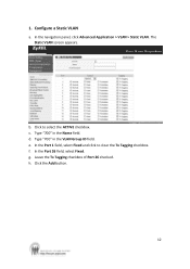
b. Click to clear the Tx Tagging checkbox. d. In the Port 1 field, select Fixed and click to select the ACTIVE checkbox. Type "700" in the VLAN Group ID field. Type "700" in the Name field. Leave the Tx Tagging checkbox of Port 26 checked. h. 1. In the navigation panel, click Advanced Application > VLAN > Static VLAN. The Static VLAN screen appears. g. In the Port 26 field, select Fixed. Click the Add button. 12 c. e. Configure a Static VLAN a. f.
b. Click to clear the Tx Tagging checkbox. d. In the Port 1 field, select Fixed and click to select the ACTIVE checkbox. Type "700" in the VLAN Group ID field. Type "700" in the Name field. Leave the Tx Tagging checkbox of Port 26 checked. h. 1. In the navigation panel, click Advanced Application > VLAN > Static VLAN. The Static VLAN screen appears. g. In the Port 26 field, select Fixed. Click the Add button. 12 c. e. Configure a Static VLAN a. f.
Support Guide
Page 13
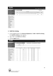
The VLAN Port Setting screen appears. Click the Apply button. 13 c. 2. b. In the navigation panel, click Advanced Application > VLAN > VLAN Port Setting. Type "700" in the PVID field of Port 1. VLAN Port Setting a.
The VLAN Port Setting screen appears. Click the Apply button. 13 c. 2. b. In the navigation panel, click Advanced Application > VLAN > VLAN Port Setting. Type "700" in the PVID field of Port 1. VLAN Port Setting a.
Support Guide
Page 14
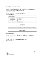
c. Click the Add button. 4. In the navigation panel, click IP Application > DHCP > VLAN. d. Configure an In-band IP Address a. Type "700" in the Default Gateway field. e. Type "192.168.1.101" in the VID field. Type "700" in the IP Address field. In the navigation panel, click Basic Setting > IP Setup. f. c. b. d. 3. In the In-band IP Addresses section, type "192.168.1.100" in the VID field. DHCP VLAN Setting a. b. Click the Add button. 14 Type "255.255.255.0" in the Remote DHCP Server 1 field. Type "192.168.1.101" in the IP Subnet Mask field. The VLAN ...
c. Click the Add button. 4. In the navigation panel, click IP Application > DHCP > VLAN. d. Configure an In-band IP Address a. Type "700" in the Default Gateway field. e. Type "192.168.1.101" in the VID field. Type "700" in the IP Address field. In the navigation panel, click Basic Setting > IP Setup. f. c. b. d. 3. In the In-band IP Addresses section, type "192.168.1.100" in the VID field. DHCP VLAN Setting a. b. Click the Add button. 14 Type "255.255.255.0" in the Remote DHCP Server 1 field. Type "192.168.1.101" in the IP Subnet Mask field. The VLAN ...
Support Guide
Page 15
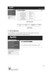
5. Save Configuration Click the Save link in the top right-hand corner of the screen to save your configuration into the Switch's nonvolatile memory. 15
5. Save Configuration Click the Save link in the top right-hand corner of the screen to save your configuration into the Switch's nonvolatile memory. 15
Support Guide
Page 16
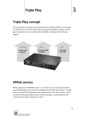
We will give an example of a service deployed in the fields, according to the following diagram. ZyXEL, the world's leading broadband access solutions provider, can demonstrate this scenario with products uniquely on its own. 16 PPPoE service PPPoE application to INTERNET access ... and VoIP traffic that are assigned into different VLANs. Triple Play 3 Triple Play concept The concept for the setting up a triple play service in VES-1616PE-54, is finally time to have the PPPoE application also implemented in the VDSL scenario.
We will give an example of a service deployed in the fields, according to the following diagram. ZyXEL, the world's leading broadband access solutions provider, can demonstrate this scenario with products uniquely on its own. 16 PPPoE service PPPoE application to INTERNET access ... and VoIP traffic that are assigned into different VLANs. Triple Play 3 Triple Play concept The concept for the setting up a triple play service in VES-1616PE-54, is finally time to have the PPPoE application also implemented in the VDSL scenario.
Support Guide
Page 17
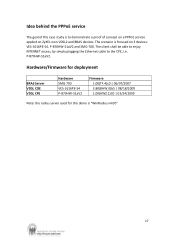
Idea behind the PPPoE service The goal of this demo is focused on ZyXEL own VDSL2 and BRAS devices. Hardware/Firmware for deployment BRAS Server VDSL COE VDSL CPE Hardware SMG-700 VES-1616PE-54 P-870HW-51aV2 Firmware 1.00(TF.4)c0 | 06/07/2007 3.80(BHW.0)b5 | 08/18/2009 1.00(AWZ.1)C0 | 03... shall be able to enjoy INTERNET access, by simply plugging the Ethernet cable to demonstrate a proof of concept on a PPPoE service applied on 3 devices: VES-1616PE-54, P-870HW-51aV2 and SMG-700.
Idea behind the PPPoE service The goal of this demo is focused on ZyXEL own VDSL2 and BRAS devices. Hardware/Firmware for deployment BRAS Server VDSL COE VDSL CPE Hardware SMG-700 VES-1616PE-54 P-870HW-51aV2 Firmware 1.00(TF.4)c0 | 06/07/2007 3.80(BHW.0)b5 | 08/18/2009 1.00(AWZ.1)C0 | 03... shall be able to enjoy INTERNET access, by simply plugging the Ethernet cable to demonstrate a proof of concept on a PPPoE service applied on 3 devices: VES-1616PE-54, P-870HW-51aV2 and SMG-700.
Support Guide
Page 18
Scenario The WAN interface in P-870HW-51aV2 shall be configured into PPPoE mode with VLAN=100. VES-1616PE-54 untags the coming PPPoE traffic from the CPE, and relay it to access INTERNET. 18 The SMG-700 shall be able to establish the PPPoE connection by authenticating the username/password with the help of the Win RADIUS server, and relay the traffic to the NAT router, to allow the client to be tagged with the correct username and password, which the egress traffic will automatically be able to the BRAS, SMG-700.
Scenario The WAN interface in P-870HW-51aV2 shall be configured into PPPoE mode with VLAN=100. VES-1616PE-54 untags the coming PPPoE traffic from the CPE, and relay it to access INTERNET. 18 The SMG-700 shall be able to establish the PPPoE connection by authenticating the username/password with the help of the Win RADIUS server, and relay the traffic to the NAT router, to allow the client to be tagged with the correct username and password, which the egress traffic will automatically be able to the BRAS, SMG-700.
Support Guide
Page 19
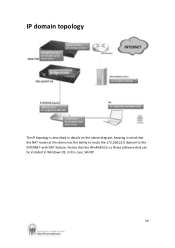
Notice that the WinRADIUS is described in details on the above diagram, keeping in this demo has the ability to route the 172.168.23.0 domain to the INTERNET with NAT feature. IP domain topology The IP topology is a (free) software that can be installed in Windows OS, in mind that the NAT router at this case, WinXP. 19
Notice that the WinRADIUS is described in details on the above diagram, keeping in this demo has the ability to route the 172.168.23.0 domain to the INTERNET with NAT feature. IP domain topology The IP topology is a (free) software that can be installed in Windows OS, in mind that the NAT router at this case, WinXP. 19
Support Guide
Page 20
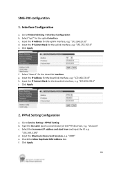
Interface Configuration a. Select "up1" for the uplink interface, e.g. Input the IP Address for the uplink Interface c. Input the IP Subnet Mask for the downlink Interface g. Click Apply f. Click Apply 2. Check the Allow Duplicate MAC Address box f. Click Apply 20 PPPoE Setting Configuration a. Select the Increment IP address and start from and input the IP, e.g. Go to Service Setting > PPPoE Setting b. "172.168.23.10" d. "255.255.255.0" i. Go to Network Setting > Interface Configuration b. Select "down1" for the uplink interface, e.g. "3000" e. Input the IP ...
Interface Configuration a. Select "up1" for the uplink interface, e.g. Input the IP Address for the uplink Interface c. Input the IP Subnet Mask for the downlink Interface g. Click Apply f. Click Apply 2. Check the Allow Duplicate MAC Address box f. Click Apply 20 PPPoE Setting Configuration a. Select the Increment IP address and start from and input the IP, e.g. Go to Service Setting > PPPoE Setting b. "172.168.23.10" d. "255.255.255.0" i. Go to Network Setting > Interface Configuration b. Select "down1" for the uplink interface, e.g. "3000" e. Input the IP ...
Support Guide
Page 21
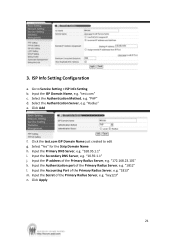
"Radius" e. "key123" n. 3. ISP Info Setting Configuration a. Go to edit g. "PAP" d. Click the test.com ISP Domain Name just created to Service Setting > ISP Info Setting b. Input the Primary DNS Server, e.g. "172.168.23.101" k. "1813" m. Select the Authentication Server, e.g. Input the Accounting Port of the Primary Radius Server, e.g. "168.95.1.1" i. Input the ISP Domain Name, e.g. Select "Yes" for the Strip Domain Name h. "1812" l. Input the Secret of the Primary Radius Server, e.g. Click Apply 21 "test.com" c. Select the Authentication Method,...
"Radius" e. "key123" n. 3. ISP Info Setting Configuration a. Go to edit g. "PAP" d. Click the test.com ISP Domain Name just created to Service Setting > ISP Info Setting b. Input the Primary DNS Server, e.g. "172.168.23.101" k. "1813" m. Select the Authentication Server, e.g. Input the Accounting Port of the Primary Radius Server, e.g. "168.95.1.1" i. Input the ISP Domain Name, e.g. Select "Yes" for the Strip Domain Name h. "1812" l. Input the Secret of the Primary Radius Server, e.g. Click Apply 21 "test.com" c. Select the Authentication Method,...