
Owner's Manual
Page 3
...of this manual, meets FCC requirements. If you to the presence of interference, which can not locate the appropriate retailer, please contact Yamaha Electronics Corp., U.S.A. 6660 Orangethorpe Ave, Buena Park, CA 90620. A polarized plug has two blades with the manufacturer's instructions. 8...to follow instructions could void your use of time. 14 Refer all instructions. 5 Do not use the product. 2 IMPORTANT: When connecting this apparatus near any heat sources such as practical. 1 Read these instructions. 2 Keep these requirements provides a reasonable level of radio...
...of this manual, meets FCC requirements. If you to the presence of interference, which can not locate the appropriate retailer, please contact Yamaha Electronics Corp., U.S.A. 6660 Orangethorpe Ave, Buena Park, CA 90620. A polarized plug has two blades with the manufacturer's instructions. 8...to follow instructions could void your use of time. 14 Refer all instructions. 5 Do not use the product. 2 IMPORTANT: When connecting this apparatus near any heat sources such as practical. 1 Read these instructions. 2 Keep these requirements provides a reasonable level of radio...

Owner's Manual
Page 4
...cover this unit with a higher voltage than specified. 13 To prevent damage by ASTANDBY/ON. this unit in the space below. Contact qualified Yamaha service personnel when any damage resulting from earphones and headphones can be reached easily. 17 Be sure to read this unit, and/or personal...operating errors before operating your local main voltage BEFORE plugging into the AC wall outlet. Danger of plug to a wall outlet until all connections are incorrectly replaced. On the top of this unit is located on switches, knobs and/or cords. 10 When disconnecting the power cable...
...cover this unit with a higher voltage than specified. 13 To prevent damage by ASTANDBY/ON. this unit in the space below. Contact qualified Yamaha service personnel when any damage resulting from earphones and headphones can be reached easily. 17 Be sure to read this unit, and/or personal...operating errors before operating your local main voltage BEFORE plugging into the AC wall outlet. Danger of plug to a wall outlet until all connections are incorrectly replaced. On the top of this unit is located on switches, knobs and/or cords. 10 When disconnecting the power cable...
Owner's Manual
Page 5
... 9 Installing batteries in the remote control 9 Using the remote control 9 Connections 10 Placing speakers 10 Connecting speakers 11 Information on jacks and cable plugs 13 Connecting a TV monitor or projector 14 Connecting other components 15 Connecting a Yamaha iPod universal dock or Bluetooth™ wireless audio receiver 16 Using the VIDEO AUX jacks on the front panel .... 16...
... 9 Installing batteries in the remote control 9 Using the remote control 9 Connections 10 Placing speakers 10 Connecting speakers 11 Information on jacks and cable plugs 13 Connecting a TV monitor or projector 14 Connecting other components 15 Connecting a Yamaha iPod universal dock or Bluetooth™ wireless audio receiver 16 Using the VIDEO AUX jacks on the front panel .... 16...
Owner's Manual
Page 6
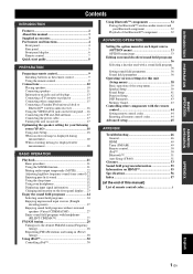
...terminal • DOCK terminal to connect a Yamaha iPod universal dock (such as YDS-11, sold separately) or Bluetooth wireless audio receiver (such as YBA-10, sold separately) ■ Automatic speaker setup features • "YPAO" (Yamaha Parametric Room Acoustic Optimizer) for ...video x 1 • Audio/Visual output [Audio] Analog x 1 [Video] Composite video x 1 • Audio output Analog x 1 ■ Proprietary Yamaha technology for the creation of sound fields • CINEMA DSP • Compressed Music Enhancer mode • Virtual CINEMA DSP • SILENT CINEMA ■ Digital ...
...terminal • DOCK terminal to connect a Yamaha iPod universal dock (such as YDS-11, sold separately) or Bluetooth wireless audio receiver (such as YBA-10, sold separately) ■ Automatic speaker setup features • "YPAO" (Yamaha Parametric Room Acoustic Optimizer) for ...video x 1 • Audio/Visual output [Audio] Analog x 1 [Video] Composite video x 1 • Audio output Analog x 1 ■ Proprietary Yamaha technology for the creation of sound fields • CINEMA DSP • Compressed Music Enhancer mode • Virtual CINEMA DSP • SILENT CINEMA ■ Digital ...

Owner's Manual
Page 8
... Changes FM/AM tuner frequencies (see page 22). M DIRECT Changes a sound field program to FM (see page 29). R AUDIO L/R (VIDEO AUX) jack For connecting the audio output cable of a camcorder or game console (see page 24). K PROGRAM l / h Changes sound field programs (see page 16). C INFO Changes ...For plugging headphones (see page 16). I Q R S A STANDBY/ON Switches this unit (see page 18). S PORTABLE (VIDEO AUX) jack For connecting the audio output cable of a portable music player (see page 22). U HDMI THROUGH Lights up during pass-through output of an HDMI signal input ...
... Changes FM/AM tuner frequencies (see page 22). M DIRECT Changes a sound field program to FM (see page 29). R AUDIO L/R (VIDEO AUX) jack For connecting the audio output cable of a camcorder or game console (see page 24). K PROGRAM l / h Changes sound field programs (see page 16). C INFO Changes ...For plugging headphones (see page 16). I Q R S A STANDBY/ON Switches this unit (see page 18). S PORTABLE (VIDEO AUX) jack For connecting the audio output cable of a portable music player (see page 22). U HDMI THROUGH Lights up during pass-through output of an HDMI signal input ...

Owner's Manual
Page 9
...(see page 16). d SPEAKERS terminal For connecting front right and left, center, surround and surround back speakers (see page 11). k Power Cable For connecting this unit to an external component (see page 14). f AV OUT Outputs audio/visual signals from a selected ... ) AV 1 COAXIAL AV 2 COAXIAL (CD) AV 3 OPTICAL AV 4 AV 5 AV 6 AV OUT AUDIO1 AUDIO2 AUDIO OUT SUBWOOFER PRE OUT e fg h i j a DOCK terminal For connecting an optional Yamaha iPod universal dock (YDS11) or Bluetooth wireless audio receiver (YBA-10) (see page 17). b HDMI OUT/HDMI 1-4 For connecting an ...
...(see page 16). d SPEAKERS terminal For connecting front right and left, center, surround and surround back speakers (see page 11). k Power Cable For connecting this unit to an external component (see page 14). f AV OUT Outputs audio/visual signals from a selected ... ) AV 1 COAXIAL AV 2 COAXIAL (CD) AV 3 OPTICAL AV 4 AV 5 AV 6 AV OUT AUDIO1 AUDIO2 AUDIO OUT SUBWOOFER PRE OUT e fg h i j a DOCK terminal For connecting an optional Yamaha iPod universal dock (YDS11) or Bluetooth wireless audio receiver (YBA-10) (see page 17). b HDMI OUT/HDMI 1-4 For connecting an ...

Owner's Manual
Page 11
...Sets remote control codes for external component operations (see page 24). Selects AUDIO inputs 1 and 2. Selects a Yamaha iPod universal dock/ Bluetooth wireless audio receiver connected to the previous screen or ends the menu display. h Tuner keys FM AM MEMORY PRESET k / n.... INTRODUCTION PREPARATION BASIC OPERATION ADVANCED OPERATION Remote control a d g h i j k l n r TRANSMIT CODE SET POWER SOURCE 1 1 5 SLEEP POWER HDMI 2 3 4 AV 2 3 4 AUDIO 6 1 2 V-AUX [ A ] [ B ] DOCK TUNER FM AM PRESET TUNING INFO MEMORY MOVIE ENHANCER SUR. Selects the FM/AM tuner. r ...
...Sets remote control codes for external component operations (see page 24). Selects AUDIO inputs 1 and 2. Selects a Yamaha iPod universal dock/ Bluetooth wireless audio receiver connected to the previous screen or ends the menu display. h Tuner keys FM AM MEMORY PRESET k / n.... INTRODUCTION PREPARATION BASIC OPERATION ADVANCED OPERATION Remote control a d g h i j k l n r TRANSMIT CODE SET POWER SOURCE 1 1 5 SLEEP POWER HDMI 2 3 4 AV 2 3 4 AUDIO 6 1 2 V-AUX [ A ] [ B ] DOCK TUNER FM AM PRESET TUNING INFO MEMORY MOVIE ENHANCER SUR. Selects the FM/AM tuner. r ...
Owner's Manual
Page 12
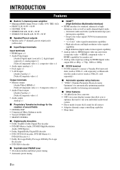
... ☞P. 15 • Connecting a Yamaha iPod universal dock or Bluetooth wireless audio receiver ☞P. 16 • Connecting the FM and AM antennas ☞P. 17 Step 4: Turn on the power Connect the power cable and turn on this unit. • Connecting the power cable •...the input source and start playback Select the component connected in the room and connect them to this unit. • Placing speakers • Connecting speakers ☞P. 10 ☞P. 11 y • This unit has a YPAO (Yamaha Parametric Room Acoustic Optimizer) that automatically optimizes this product...
... ☞P. 15 • Connecting a Yamaha iPod universal dock or Bluetooth wireless audio receiver ☞P. 16 • Connecting the FM and AM antennas ☞P. 17 Step 4: Turn on the power Connect the power cable and turn on this unit. • Connecting the power cable •...the input source and start playback Select the component connected in the room and connect them to this unit. • Placing speakers • Connecting speakers ☞P. 10 ☞P. 11 y • This unit has a YPAO (Yamaha Parametric Room Acoustic Optimizer) that automatically optimizes this product...

Owner's Manual
Page 14
... and effect sounds. Use a subwoofer with the front surfaces of the screen from each other, ideally at the same distance as the Yamaha Active Servo Processing Subwoofer System. Place these speakers at the rear left and right speakers. SL 60˚ SL 80˚ SBL ...■ Subwoofer (SW) The subwoofer speaker is for bass sounds and lowfrequency effect (LFE) sounds included in the 7.1channel speaker layout. Connections Placing speakers This unit supports up to reduce reflections from the surround left and right channel sound signals are output from a wall. 10 En...
... and effect sounds. Use a subwoofer with the front surfaces of the screen from each other, ideally at the same distance as the Yamaha Active Servo Processing Subwoofer System. Place these speakers at the rear left and right speakers. SL 60˚ SL 80˚ SBL ...■ Subwoofer (SW) The subwoofer speaker is for bass sounds and lowfrequency effect (LFE) sounds included in the 7.1channel speaker layout. Connections Placing speakers This unit supports up to reduce reflections from the surround left and right channel sound signals are output from a wall. 10 En...

Owner's Manual
Page 15
INTRODUCTION PREPARATION BASIC OPERATION Connections Connecting speakers When you connect speakers, connect them to the respective terminals as follows, according to your speaker layout. ba c gf DMI 3 HDMI 4 FRONT SPEAKERS CENTER SURROUND SURROUND BACK/BI-AMP ■ 7.1-...
INTRODUCTION PREPARATION BASIC OPERATION Connections Connecting speakers When you connect speakers, connect them to the respective terminals as follows, according to your speaker layout. ba c gf DMI 3 HDMI 4 FRONT SPEAKERS CENTER SURROUND SURROUND BACK/BI-AMP ■ 7.1-...

Owner's Manual
Page 16
...when you use the magnetically shielded speakers, place the speakers away from the end of insulation from the monitor. • Use speakers with a tweeter. Connect one end of the colored/striped cable to the "+" (red) terminal of this unit and the other end to that of your speaker. •...the other cable to the instruction manuals of insulated cables running side by side in general. This could damage this unit. Front speakers Right Left Connecting the banana plug (Except U.K., Europe, Asia and Korea models) Tighten the knob, and then insert the banana plug into the hole, and ...
...when you use the magnetically shielded speakers, place the speakers away from the end of insulation from the monitor. • Use speakers with a tweeter. Connect one end of the colored/striped cable to the "+" (red) terminal of this unit and the other end to that of your speaker. •...the other cable to the instruction manuals of insulated cables running side by side in general. This could damage this unit. Front speakers Right Left Connecting the banana plug (Except U.K., Europe, Asia and Korea models) Tighten the knob, and then insert the banana plug into the hole, and ...
Owner's Manual
Page 17
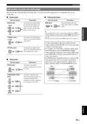
...VIDEO jacks COMPONENT VIDEO PR PR (red) PB PB (blue) Y Y (green) To transmit component video signals that you are connected, connect both VIDEO jack and COMPONENT VIDEO jack in MONITOR OUT for optical digital audio signals. HDMI jacks HDMI HDMI To transmit digital video ...This unit has the following input and output jacks. Use component video cables. Use video pin cables. INTRODUCTION PREPARATION BASIC OPERATION Connections Information on HDMI connections (see page 23). Use stereo pin cables. Use HDMI cables. PR PB Y VIDEO Repeat PR PB Y VIDEO Converted...
...VIDEO jacks COMPONENT VIDEO PR PR (red) PB PB (blue) Y Y (green) To transmit component video signals that you are connected, connect both VIDEO jack and COMPONENT VIDEO jack in MONITOR OUT for optical digital audio signals. HDMI jacks HDMI HDMI To transmit digital video ...This unit has the following input and output jacks. Use component video cables. Use video pin cables. INTRODUCTION PREPARATION BASIC OPERATION Connections Information on HDMI connections (see page 23). Use stereo pin cables. Use HDMI cables. PR PB Y VIDEO Repeat PR PB Y VIDEO Converted...
Owner's Manual
Page 18
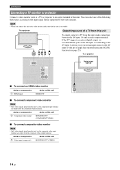
... output, we recommend that this unit is on this unit, make connection between the AV input 1-6 and an audio output terminal. Jacks on components c Video input (composite) Jacks on standby. Connecting to the AV input 1 allows you to switch an input source to an output ...on this unit MONITOR OUT (COMPONENT VIDEO) ■ To connect composite video monitor Note • Only video signals input from this unit. Connections Connecting a TV monitor or projector Connect a video monitor such as a TV or projector to the AV input 1 with just a single key operation using the SCENE ...
... output, we recommend that this unit is on this unit, make connection between the AV input 1-6 and an audio output terminal. Jacks on components c Video input (composite) Jacks on standby. Connecting to the AV input 1 allows you to switch an input source to an output ...on this unit MONITOR OUT (COMPONENT VIDEO) ■ To connect composite video monitor Note • Only video signals input from this unit. Connections Connecting a TV monitor or projector Connect a video monitor such as a TV or projector to the AV input 1 with just a single key operation using the SCENE ...
Owner's Manual
Page 19
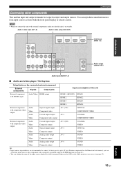
... components This unit has input and output terminals for respective input and output sources. If your Yamaha component has the Remote in/out terminal, you connect this unit to the external components, make sure that this unit External component with HDMI output Audio/Video HDMI ...DVD) HDMI 1 COMPONENT VIDEO PR HDMI 2 FM GND AM PB Y VIDEO MONITOR OUT HDMI 3 HDMI 4 FRONT OPTICAL ( TV ) AV 1 COAXIAL AV 2 COAXIAL (CD) AV 3 OPTICAL AV 4 AV 5 AV 6 AV OUT AUDIO1 AUDIO2 AUDIO OUT HDMI input (HDMI 1-4) CE Audio output (AUDIO OUT) Audio input (AUDIO 1-2) ■ Audio and video ...
... components This unit has input and output terminals for respective input and output sources. If your Yamaha component has the Remote in/out terminal, you connect this unit to the external components, make sure that this unit External component with HDMI output Audio/Video HDMI ...DVD) HDMI 1 COMPONENT VIDEO PR HDMI 2 FM GND AM PB Y VIDEO MONITOR OUT HDMI 3 HDMI 4 FRONT OPTICAL ( TV ) AV 1 COAXIAL AV 2 COAXIAL (CD) AV 3 OPTICAL AV 4 AV 5 AV 6 AV OUT AUDIO1 AUDIO2 AUDIO OUT HDMI input (HDMI 1-4) CE Audio output (AUDIO OUT) Audio input (AUDIO 1-2) ■ Audio and video ...
Owner's Manual
Page 20
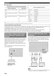
... AV 5 AV 6 AUDIO AUDIO AUDIO 1 AUDIO AUDIO 2 y • We recommend connecting the coaxial digital output terminal of this unit. An HDMI input signal, COMPONENT VIDEO input signal or digital audio input signal cannot be output. Connecting a Yamaha iPod universal dock or Bluetooth™ wireless audio receiver ...the DOCK jack, to turn down the volume of a CD player to the AV3 jack. You can connect a Yamaha iPod universal dock (YDS-11, sold separately) or a Bluetooth wireless audio receiver (YBA-10, sold separately). VOLUME l PRESET h FM BD/DVD SCENE TV CD AM RADIO l TUNING...
... AV 5 AV 6 AUDIO AUDIO AUDIO 1 AUDIO AUDIO 2 y • We recommend connecting the coaxial digital output terminal of this unit. An HDMI input signal, COMPONENT VIDEO input signal or digital audio input signal cannot be output. Connecting a Yamaha iPod universal dock or Bluetooth™ wireless audio receiver ...the DOCK jack, to turn down the volume of a CD player to the AV3 jack. You can connect a Yamaha iPod universal dock (YDS-11, sold separately) or a Bluetooth wireless audio receiver (YBA-10, sold separately). VOLUME l PRESET h FM BD/DVD SCENE TV CD AM RADIO l TUNING...
Owner's Manual
Page 21
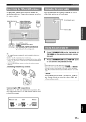
... the AM loop antenna away from the AC wall outlet. Indoor FM antenna Outdoor AM antenna Connect a 5 to 10 m (16 to turn off this antenna). For more details, consult the nearest authorized Yamaha dealer or service center. • Always use an outdoor antenna. Assembling the AM loop antenna...electricity even in the moist ground. y • The unit needs a few seconds until ready to play back. • You can connect either wire to the AM terminal and the other to the respective jacks. Press and hold Insert Release ADVANCED OPERATION ADDITIONAL INFORMATION APPENDIX English 17...
... the AM loop antenna away from the AC wall outlet. Indoor FM antenna Outdoor AM antenna Connect a 5 to 10 m (16 to turn off this antenna). For more details, consult the nearest authorized Yamaha dealer or service center. • Always use an outdoor antenna. Assembling the AM loop antenna...electricity even in the moist ground. y • The unit needs a few seconds until ready to play back. • You can connect either wire to the AM terminal and the other to the respective jacks. Press and hold Insert Release ADVANCED OPERATION ADDITIONAL INFORMATION APPENDIX English 17...

Owner's Manual
Page 22
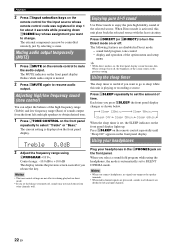
...frequency controls of the connected subwoofer are set to the maximum. Start [ ]/[ ]:Up/Down [ENTER]:Start y • You can bring up the above menu screen from this unit automatically adjusts the output characteristics of your listening room (YPAO) This unit has a Yamaha Parametric Acoustic Optimizer (...press nCursor k to select "EQ Type" and then press nCursor l / h. VOLUME CROSSOVER/ HIGH CUT MIN MAX MIN MAX Subwoofer 2 Connect the supplied optimizer microphone to produce a cohesive sound field based on the front panel. The equalizer is set to "Flat." 18 En Natural...
...frequency controls of the connected subwoofer are set to the maximum. Start [ ]/[ ]:Up/Down [ENTER]:Start y • You can bring up the above menu screen from this unit automatically adjusts the output characteristics of your listening room (YPAO) This unit has a Yamaha Parametric Acoustic Optimizer (...press nCursor k to select "EQ Type" and then press nCursor l / h. VOLUME CROSSOVER/ HIGH CUT MIN MAX MIN MAX Subwoofer 2 Connect the supplied optimizer microphone to produce a cohesive sound field based on the front panel. The equalizer is set to "Flat." 18 En Natural...
Owner's Manual
Page 23
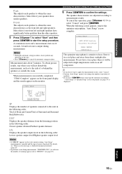
... Setup RESULT SP : DIST: LVL : . >Set 3/4/0.1 8.0/ 8.5ft -3.5/ +4.5dB Cancel [p]/[[]:Select [ENTER]:Finish SP Displays the number of speakers connected to this if your speakers have significantly better qualities than the other speakers. 5 Press nCursor n to select "Start" and then press nENTER to start... the speaker distance from direct sunlight after measurement. To obtain precise results, stay where you do not perform any operation on an AV component. When measurement is displayed during measurement" (page 20). • If problems occur during measurement. y • If you...
... Setup RESULT SP : DIST: LVL : . >Set 3/4/0.1 8.0/ 8.5ft -3.5/ +4.5dB Cancel [p]/[[]:Select [ENTER]:Finish SP Displays the number of speakers connected to this if your speakers have significantly better qualities than the other speakers. 5 Press nCursor n to select "Start" and then press nENTER to start... the speaker distance from direct sunlight after measurement. To obtain precise results, stay where you do not perform any operation on an AV component. When measurement is displayed during measurement" (page 20). • If problems occur during measurement. y • If you...

Owner's Manual
Page 25
...input source is output. Input source Sound field program BD/DVD TV CD RADIO HDMI 1 AV 1 AV 3 TUNER Straight Straight Straight 7ch Enhancer y • When this unit by digital connection and play back a DTS-CD, noise may cause a speaker malfunction. Note • ... component for each input source. AV1 y • You can operate an external component with one key. Volume VOL. Connect the playback component to TUNER input. INTRODUCTION PREPARATION BASIC OPERATION ADVANCED OPERATION BASIC OPERATION Playback Basic procedure 1 Turn on the front...
...input source is output. Input source Sound field program BD/DVD TV CD RADIO HDMI 1 AV 1 AV 3 TUNER Straight Straight Straight 7ch Enhancer y • When this unit by digital connection and play back a DTS-CD, noise may cause a speaker malfunction. Note • ... component for each input source. AV1 y • You can operate an external component with one key. Volume VOL. Connect the playback component to TUNER input. INTRODUCTION PREPARATION BASIC OPERATION ADVANCED OPERATION BASIC OPERATION Playback Basic procedure 1 Turn on the front...
Owner's Manual
Page 26
... high fidelity sound of the option menu and setup menu y • While direct mode is displayed on the front panel display. Notes • When you connect headphones, no signals are output at the speaker terminals. • When multi-channel signals are processed, sounds in all channels are disabled in Direct mode...
... high fidelity sound of the option menu and setup menu y • While direct mode is displayed on the front panel display. Notes • When you connect headphones, no signals are output at the speaker terminals. • When multi-channel signals are processed, sounds in all channels are disabled in Direct mode...


