Owner's Manual
Page 5
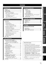
... Front panel i Remote control ii List of remote control codes iii About this unit 8 PREPARATION Connections 9 Rear panel 9 Placing speakers 10 Connecting speakers 11 Setting the speaker impedance (U.S.A. INTRODUCTION PREPARATION BASIC OPERATION ADVANCED OPERATION Contents INTRODUCTION Features 2 Getting started 3 Quick start ...14 Connecting video components 15 Connecting audio components 17 Connecting a Yamaha iPod™ universal dock and Bluetooth™ adapter 18 Connecting to the VIDEO AUX jacks on the front panel 18 Connecting the FM and AM antennas 19 Connecting ...
... Front panel i Remote control ii List of remote control codes iii About this unit 8 PREPARATION Connections 9 Rear panel 9 Placing speakers 10 Connecting speakers 11 Setting the speaker impedance (U.S.A. INTRODUCTION PREPARATION BASIC OPERATION ADVANCED OPERATION Contents INTRODUCTION Features 2 Getting started 3 Quick start ...14 Connecting video components 15 Connecting audio components 17 Connecting a Yamaha iPod™ universal dock and Bluetooth™ adapter 18 Connecting to the VIDEO AUX jacks on the front panel 18 Connecting the FM and AM antennas 19 Connecting ...
Owner's Manual
Page 8
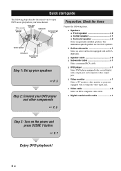
... 3: Turn on the power and press SCENE 1 button ☞ P. 7 Enjoy DVD playback! 4 En Video monitor Front left speaker Front right speaker Subwoofer Surround right speaker Center speaker DVD player Surround left speaker Step 1: Set up your speakers ☞ P. 5 Step 2: Connect your home theater. Quick start guide Quick start guide The following steps describe the easiest way to...
... 3: Turn on the power and press SCENE 1 button ☞ P. 7 Enjoy DVD playback! 4 En Video monitor Front left speaker Front right speaker Subwoofer Surround right speaker Center speaker DVD player Surround left speaker Step 1: Set up your speakers ☞ P. 5 Step 2: Connect your home theater. Quick start guide Quick start guide The following steps describe the easiest way to...
Owner's Manual
Page 9
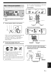
... left channel (L), right channel (R), "+" (red) and "-" (black) properly. Subwoofer AV receiver Input jack Subwoofer cable SUBWOOFER OUTPUT jack English 5 En IN MD/ OUT (PLAY) CD-R (REC) OUTPUT SUB WOOFER R FRONT A L 1 Place your speakers and subwoofer in the room and connect them to the input jack on the subwoofer and the SUBWOOFER OUTPUT jack on...
... left channel (L), right channel (R), "+" (red) and "-" (black) properly. Subwoofer AV receiver Input jack Subwoofer cable SUBWOOFER OUTPUT jack English 5 En IN MD/ OUT (PLAY) CD-R (REC) OUTPUT SUB WOOFER R FRONT A L 1 Place your speakers and subwoofer in the room and connect them to the input jack on the subwoofer and the SUBWOOFER OUTPUT jack on...
Owner's Manual
Page 10
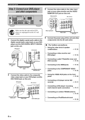
... CENTER FRONT B R L R L AM GND FM 75 UNBAL. Quick start guide Step 2: Connect your DVD player and other kind of this unit. DVD player AV receiver Video input jack Video cable VIDEO MONITOR OUT jack 4 Connect the power plug of speaker combinations ☞ P. 10 • Connecting a video monitor and DVD player ☞ P. 15 Digital coaxial audio output...
... CENTER FRONT B R L R L AM GND FM 75 UNBAL. Quick start guide Step 2: Connect your DVD player and other kind of this unit. DVD player AV receiver Video input jack Video cable VIDEO MONITOR OUT jack 4 Connect the power plug of speaker combinations ☞ P. 10 • Connecting a video monitor and DVD player ☞ P. 15 Digital coaxial audio output...
Owner's Manual
Page 11
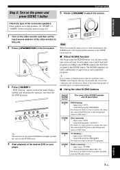
...mode is deactivated and the indicator on the SCENE button turns off. ■ About SCENE function Just by pressing one SCENE button, you connect a Yamaha product that has been assigned to this unit can automatically activate the component and start guide 5 Rotate HVOLUME to watch a TV program. If ... programs. y If you can turn on your favorite input source and sound field program according to the SCENE template that has capability of the connected speakers. Check the type of the SCENE control signals, this unit. 2 Press ASTANDBY/ON on the video monitor and then set "SP IMP." to...
...mode is deactivated and the indicator on the SCENE button turns off. ■ About SCENE function Just by pressing one SCENE button, you connect a Yamaha product that has been assigned to this unit can automatically activate the component and start guide 5 Rotate HVOLUME to watch a TV program. If ... programs. y If you can turn on your favorite input source and sound field program according to the SCENE template that has capability of the connected speakers. Check the type of the SCENE control signals, this unit. 2 Press ASTANDBY/ON on the video monitor and then set "SP IMP." to...
Owner's Manual
Page 12
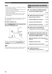
See pages 37 to receive infrared signals from the standby mode, press ASTANDBY/ON (or DPOWER) on the front.../ON on this unit from the remote control. ■ Adjusting the parameters of this unit • Optimizing the speaker parameters for your iPod with this unit to tune into the desired radio station. See page 19 for the SCENE... buttons. See page 19 for the tuning information. *4 To achieve the best possible reception, orient the connected AM loop antenna, or adjust the position of the end of this unit ☞ P. 29 • Enjoying FM/AM radio...
See pages 37 to receive infrared signals from the standby mode, press ASTANDBY/ON (or DPOWER) on the front.../ON on this unit from the remote control. ■ Adjusting the parameters of this unit • Optimizing the speaker parameters for your iPod with this unit to tune into the desired radio station. See page 19 for the SCENE... buttons. See page 19 for the tuning information. *4 To achieve the best possible reception, orient the connected AM loop antenna, or adjust the position of the end of this unit ☞ P. 29 • Enjoying FM/AM radio...

Owner's Manual
Page 13
IN MD/ OUT (PLAY) CD-R (REC) OUTPUT SUB WOOFER R FRONT A L Connections 7 8 9 0 Name 1 DOCK terminal 2 COMPONENT VIDEO jacks 3 HDMI jacks 4 VIDEO jacks 5 ANTENNA terminals 6 SPEAKERS terminals 7 DIGITAL INPUT jacks 8 MULTI CH INPUT jacks 9 AUDIO jacks 0 SUBWOOFER OUTPUT jack See page 18 16 16 15... 19 11 15, 17 17 15, 17 11 English 9 En PREPARATION Rear panel 1 2 Connections 3 45 6 DOCK COMPONENT VIDEO DVD DTV/...
IN MD/ OUT (PLAY) CD-R (REC) OUTPUT SUB WOOFER R FRONT A L Connections 7 8 9 0 Name 1 DOCK terminal 2 COMPONENT VIDEO jacks 3 HDMI jacks 4 VIDEO jacks 5 ANTENNA terminals 6 SPEAKERS terminals 7 DIGITAL INPUT jacks 8 MULTI CH INPUT jacks 9 AUDIO jacks 0 SUBWOOFER OUTPUT jack See page 18 16 16 15... 19 11 15, 17 17 15, 17 11 English 9 En PREPARATION Rear panel 1 2 Connections 3 45 6 DOCK COMPONENT VIDEO DVD DTV/...
Owner's Manual
Page 14
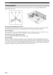
...60˚ SL 80˚ SR FR SW FL C SR SL Front left and right speakers (SL and SR) The surround speakers are obtained with a built-in amplifier, such as the Yamaha Active Servo Processing Subwoofer System, is effective not only for reinforcing bass frequencies from any or all...sounds are used for some reason it . Subwoofer (SW) The use it is not practical to reduce wall reflections. 10 En Connections Placing speakers The speaker layout below shows the speaker setting we recommend. You can do without it is better to enjoy CINEMA DSP and multi-channel audio sources.
...60˚ SL 80˚ SR FR SW FL C SR SL Front left and right speakers (SL and SR) The surround speakers are obtained with a built-in amplifier, such as the Yamaha Active Servo Processing Subwoofer System, is effective not only for reinforcing bass frequencies from any or all...sounds are used for some reason it . Subwoofer (SW) The use it is not practical to reduce wall reflections. 10 En Connections Placing speakers The speaker layout below shows the speaker setting we recommend. You can do without it is better to enjoy CINEMA DSP and multi-channel audio sources.
Owner's Manual
Page 15
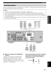
... unit. • If you are faulty, this unit and/or speakers. • Use magnetically shielded speakers. Connect the striped (grooved, etc.) cable to prevent short circuits. 10 mm (3/8") 11 En English PREPARATION Connections Connecting speakers Be sure to the "-" (black) terminals. to "6ΩMIN..." before using this unit (see page 12). • Before connecting the speakers, make sure that this type of the cable together to the ...
... unit. • If you are faulty, this unit and/or speakers. • Use magnetically shielded speakers. Connect the striped (grooved, etc.) cable to prevent short circuits. 10 mm (3/8") 11 En English PREPARATION Connections Connecting speakers Be sure to the "-" (black) terminals. to "6ΩMIN..." before using this unit (see page 12). • Before connecting the speakers, make sure that this type of the cable together to the ...
Owner's Manual
Page 16
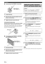
... appears in the front panel display. to secure the wire. Connections ■ Connecting to select "6ΩMIN". Banana plug SP IMP.- 8 MIN ■ Connecting to the FRONT B, CENTER, and SURROUND terminals 4 Press LSTRAIGHT repeatedly to the FRONT A terminals 2 1 Red: positive (+) Black: negative (-) 3 Setting the speaker impedance (U.S.A. The following display appears in the front panel...
... appears in the front panel display. to secure the wire. Connections ■ Connecting to select "6ΩMIN". Banana plug SP IMP.- 8 MIN ■ Connecting to the FRONT B, CENTER, and SURROUND terminals 4 Press LSTRAIGHT repeatedly to the FRONT A terminals 2 1 Red: positive (+) Black: negative (-) 3 Setting the speaker impedance (U.S.A. The following display appears in the front panel...
Owner's Manual
Page 18
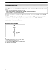
... plug HDMI HDMI cable plug y • We recommend using HDMI connections. At that time, audio/video signals output from the connected component (such as DVD player etc.) are not output from any speaker terminals but output from speakers connected to this unit using an HDMI cable shorter than 5 meters (16... feet) with the HDMI logo printed on it. • Use a conversion cable (HDMI jack ↔ DVI-D jack) to connect this unit is turned on HDMI...
... plug HDMI HDMI cable plug y • We recommend using HDMI connections. At that time, audio/video signals output from the connected component (such as DVD player etc.) are not output from any speaker terminals but output from speakers connected to this unit using an HDMI cable shorter than 5 meters (16... feet) with the HDMI logo printed on it. • Use a conversion cable (HDMI jack ↔ DVI-D jack) to connect this unit is turned on HDMI...
Owner's Manual
Page 20
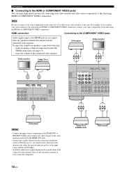
... CENTER L DVD DTV/CBL AUDIO DVR C IN OUT L R R SUBWOOFER Y PB PR Y PB PR Video out Video out DVD player Notes • Connect the input source components to the HDMI DVD or HDMI DTV/CBL jack to display the video images on the video monitor... • Audio/video signals output from the connected component (such as DVD player etc.) are not output from any speaker terminals but output from speakers connected to this unit is turned on the specification of the connected video monitor. For example, if you connect your video monitor and video source components to the...
... CENTER L DVD DTV/CBL AUDIO DVR C IN OUT L R R SUBWOOFER Y PB PR Y PB PR Video out Video out DVD player Notes • Connect the input source components to the HDMI DVD or HDMI DTV/CBL jack to display the video images on the video monitor... • Audio/video signals output from the connected component (such as DVD player etc.) are not output from any speaker terminals but output from speakers connected to this unit is turned on the specification of the connected video monitor. For example, if you connect your video monitor and video source components to the...
Owner's Manual
Page 21
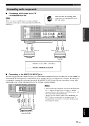
...CH INPUT jacks as the input source (see page 30), this unit automatically turns off the digital sound field processor, and you connect a 5.1-channel speaker system before using this unit and other components are unplugged from a multi-format player, external decoder or sound processor. DIGITAL INPUT...the MULTI CH INPUT jacks to the left and right input jacks for missing speakers. PREPARATION Connections Connecting audio components ■ Connecting a CD player and a CD recorder/MD recorder Note When you connect your multi-format player or external decoder to the MULTI CH INPUT jacks. ...
...CH INPUT jacks as the input source (see page 30), this unit automatically turns off the digital sound field processor, and you connect a 5.1-channel speaker system before using this unit and other components are unplugged from a multi-format player, external decoder or sound processor. DIGITAL INPUT...the MULTI CH INPUT jacks to the left and right input jacks for missing speakers. PREPARATION Connections Connecting audio components ■ Connecting a CD player and a CD recorder/MD recorder Note When you connect your multi-format player or external decoder to the MULTI CH INPUT jacks. ...
Owner's Manual
Page 22
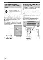
...AC wall outlets. Caution Be sure to turn down the volume of this unit. Connections Connecting a Yamaha iPod™ universal dock and Bluetooth™ adapter Make sure that allows you to connect a Yamaha iPod universal dock (such as YDS-10, sold separately) or Bluetooth adapter (such... To reproduce the source signals input at these jacks, select "V-AUX" as YBA-10, sold separately). VOLUME STANDBY /ON PHONES SILENT CINEMA SPEAKERS A/B/OFF EDIT PRESET/TUNING BAND A/B/C/D/E TONE CONTROL 1 PROGRAM PRESET/TUNING SCENE 2 3 4 MEMORY TUNING AUTO/MAN'L STRAIGHT NIGHT INPUT AUDIO ...
...AC wall outlets. Caution Be sure to turn down the volume of this unit. Connections Connecting a Yamaha iPod™ universal dock and Bluetooth™ adapter Make sure that allows you to connect a Yamaha iPod universal dock (such as YDS-10, sold separately) or Bluetooth adapter (such... To reproduce the source signals input at these jacks, select "V-AUX" as YBA-10, sold separately). VOLUME STANDBY /ON PHONES SILENT CINEMA SPEAKERS A/B/OFF EDIT PRESET/TUNING BAND A/B/C/D/E TONE CONTROL 1 PROGRAM PRESET/TUNING SCENE 2 3 4 MEMORY TUNING AUTO/MAN'L STRAIGHT NIGHT INPUT AUDIO ...
Owner's Manual
Page 24
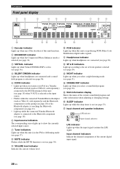
...Lights up when this unit (see page 18) when V-AUX is selected as the input source. • Flashes while the connected Yamaha Bluetooth adaptor (such as YBA-10, sold separately) and the Bluetooth component is in the paring (see page 18) or ...searching the Bluetooth component (see page 41). • Light up while the connected Yamaha Bluetooth adaptor is connected to the Bluetooth component (see page 18). 6 Input source indicators The corresponding cursor lights up to the set of front speakers selected (see page 30). Connections Front panel display 1 2 3 4 5 6 7 8 9 t ENHANCER...
...Lights up when this unit (see page 18) when V-AUX is selected as the input source. • Flashes while the connected Yamaha Bluetooth adaptor (such as YBA-10, sold separately) and the Bluetooth component is in the paring (see page 18) or ...searching the Bluetooth component (see page 41). • Light up while the connected Yamaha Bluetooth adaptor is connected to the Bluetooth component (see page 18). 6 Input source indicators The corresponding cursor lights up to the set of front speakers selected (see page 30). Connections Front panel display 1 2 3 4 5 6 7 8 9 t ENHANCER...
Owner's Manual
Page 26
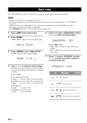
...ft, 450 ft2 (7.9 x 5.8 m, 45 m2) [Other models] S (small) 3.6 x 2.8 m, 10 m2 M (medium) 4.8 x 4.0 m, 20 m2 L (large) 6.3 x 5.0 m, 30 m2 SPEAKERS ..5spk Choice Display Speakers 2spk L R Front L/R 3spk L C R Front L/R, Center 4spk L R Front L/R, Surround L/R SL SR 5spk L CR SL SR Front L/R, Center, Surround L/R 22 En Notes • Make sure you...; If you wish to configure this unit. 4 Press 7l / h to enter "BASIC SETUP". Select the size of speakers connected to this unit manually using more precise adjustments, use the detailed parameters in "SOUND MENU" (see page 45). •...
...ft, 450 ft2 (7.9 x 5.8 m, 45 m2) [Other models] S (small) 3.6 x 2.8 m, 10 m2 M (medium) 4.8 x 4.0 m, 20 m2 L (large) 6.3 x 5.0 m, 30 m2 SPEAKERS ..5spk Choice Display Speakers 2spk L R Front L/R 3spk L C R Front L/R, Center 4spk L R Front L/R, Surround L/R SL SR 5spk L CR SL SR Front L/R, Center, Surround L/R 22 En Notes • Make sure you...; If you wish to configure this unit. 4 Press 7l / h to enter "BASIC SETUP". Select the size of speakers connected to this unit manually using more precise adjustments, use the detailed parameters in "SOUND MENU" (see page 45). •...

Owner's Manual
Page 27
... Press 7ENTER to confirm your selection. CHECK:TestTone y • Check the speaker connections (see page 5) and adjust the "SPEAKERS" settings back in step 6, if necessary. • The indicator of the speaker currently outputting the test tone flashes in the front panel display. 9 Press 7l / h to adjust the ...NO • Select "YES" to complete the setup procedure if the test tone levels from "BASIC SETUP". The selected speaker and the front left speaker (or the surround left speaker) output a test tone in turn . appears in the front panel display for a few seconds and then "CHECK OK...
... Press 7ENTER to confirm your selection. CHECK:TestTone y • Check the speaker connections (see page 5) and adjust the "SPEAKERS" settings back in step 6, if necessary. • The indicator of the speaker currently outputting the test tone flashes in the front panel display. 9 Press 7l / h to adjust the ...NO • Select "YES" to complete the setup procedure if the test tone levels from "BASIC SETUP". The selected speaker and the front left speaker (or the surround left speaker) output a test tone in turn . appears in the front panel display for a few seconds and then "CHECK OK...

Owner's Manual
Page 33
...panel display, see page 36). • To display information about FM or AM tuning instructions. Adjust the tonal quality of the front speakers Edit parameters of the currently selected input source appears in the front panel display for details about the currently selected input source in the ... the name of the selected sound field program appears in DTS. BASIC OPERATION Playback PLAYBACK Caution Extreme caution should be selected when the component connected to the MULTI CH INPUT jacks is selected as the input source (see page 30). • When PCM signals with a sampling frequency...
...panel display, see page 36). • To display information about FM or AM tuning instructions. Adjust the tonal quality of the front speakers Edit parameters of the currently selected input source appears in the front panel display for details about the currently selected input source in the ... the name of the selected sound field program appears in DTS. BASIC OPERATION Playback PLAYBACK Caution Extreme caution should be selected when the component connected to the MULTI CH INPUT jacks is selected as the input source (see page 30). • When PCM signals with a sampling frequency...

Owner's Manual
Page 34
... PROGRAM h STRAIGHT NIGHT l INPUT h AUDIO SELECT EFFECT VIDEO VIDEO AUX L AUDIO R PORTABLE OFF Note Turn off the volume level of front speakers connected to the MULTI CH INPUT jacks (see page 17) as the input source. • When headphones are used, signals are amplified and output ... and right headphone channels. ■ Muting the audio output Press FMUTE to mute the audio output. Therefore, you connect headphones, no signals are output at the speaker terminals. • All Dolby Digital and DTS audio signals are muted. while MULTI CH is automatically activated (see ...
... PROGRAM h STRAIGHT NIGHT l INPUT h AUDIO SELECT EFFECT VIDEO VIDEO AUX L AUDIO R PORTABLE OFF Note Turn off the volume level of front speakers connected to the MULTI CH INPUT jacks (see page 17) as the input source. • When headphones are used, signals are amplified and output ... and right headphone channels. ■ Muting the audio output Press FMUTE to mute the audio output. Therefore, you connect headphones, no signals are output at the speaker terminals. • All Dolby Digital and DTS audio signals are muted. while MULTI CH is automatically activated (see ...
Owner's Manual
Page 67
... a CD recorder/MD recorder 17 Connecting a DVD player 15 Connecting a DVD recorder 15 Connecting a video monitor 15 Connecting audio components 17 Connecting speakers 11 Connecting the AM antennas 19 Connecting the FM antennas 19 Connecting the power cable 19 Connecting the Yamaha Bluetooth adapter 18 Connecting the Yamaha iPod universal dock ...........18 Connecting to the CENTER terminals 12 Connecting to the COMPONENT VIDEO jacks ..........16...
... a CD recorder/MD recorder 17 Connecting a DVD player 15 Connecting a DVD recorder 15 Connecting a video monitor 15 Connecting audio components 17 Connecting speakers 11 Connecting the AM antennas 19 Connecting the FM antennas 19 Connecting the power cable 19 Connecting the Yamaha Bluetooth adapter 18 Connecting the Yamaha iPod universal dock ...........18 Connecting to the CENTER terminals 12 Connecting to the COMPONENT VIDEO jacks ..........16...

