
Owners Manual
Page 2
...the apparatus has been exposed to Article 820-40 of the NEC that provides guidelines for replacement of the obsolete outlet. 10 Protect the power cord from the apparatus. 11 Only use this apparatus during lightning storms or when unused for your sensitive hearing. We Want You Listening... specified by the manufacturer. 12 Use only with the cart, stand, tripod, bracket, or table specified by playing it is too late, YAMAHA and the Electronic Industries Association's Consumer Electronics Group recommend you to avoid prolonged exposure from tip-over. 13 Unplug this apparatus near water. 6...
...the apparatus has been exposed to Article 820-40 of the NEC that provides guidelines for replacement of the obsolete outlet. 10 Protect the power cord from the apparatus. 11 Only use this apparatus during lightning storms or when unused for your sensitive hearing. We Want You Listening... specified by the manufacturer. 12 Use only with the cart, stand, tripod, bracket, or table specified by playing it is too late, YAMAHA and the Electronic Industries Association's Consumer Electronics Group recommend you to avoid prolonged exposure from tip-over. 13 Unplug this apparatus near water. 6...

Owners Manual
Page 3
Utilize power outlets that your use only high quality shielded cables. In the case of interference, which can not locate the appropriate retailer, please contact Yamaha Electronics Corp., U.S.A. 6660 Orangethorpe Ave, Buena Park, CA 90620. Cable/s supplied with the requirements listed .../uses radio frequencies and, if not installed and used . The above statements apply ONLY to eliminate the problem by Yamaha Corporation of other electronic devices. IMPORTANT SAFETY INSTRUCTIONS FCC INFORMATION (for Class "B" digital devices. Compliance with FCC regulations does...
Utilize power outlets that your use only high quality shielded cables. In the case of interference, which can not locate the appropriate retailer, please contact Yamaha Electronics Corp., U.S.A. 6660 Orangethorpe Ave, Buena Park, CA 90620. Cable/s supplied with the requirements listed .../uses radio frequencies and, if not installed and used . The above statements apply ONLY to eliminate the problem by Yamaha Corporation of other electronic devices. IMPORTANT SAFETY INSTRUCTIONS FCC INFORMATION (for Class "B" digital devices. Compliance with FCC regulations does...

Owners Manual
Page 4
...the finish. this unit in a safe place for your local main voltage BEFORE plugging into the AC main supply. YAMAHA will not be used. vacation), disconnect the AC power plug from the wall outlet. 16 Install this unit for any service is designed to consume a very small quantity ..., dry cloth. 12 Only voltage specified on switches, knobs and/or cords. 10 When disconnecting the power cable from direct sunlight, heat sources, vibration, dust, moisture, and/or cold. Contact qualified YAMAHA service personnel when any reasons. 15 When not planning to use of plug to this unit. 6 Do...
...the finish. this unit in a safe place for your local main voltage BEFORE plugging into the AC main supply. YAMAHA will not be used. vacation), disconnect the AC power plug from the wall outlet. 16 Install this unit for any service is designed to consume a very small quantity ..., dry cloth. 12 Only voltage specified on switches, knobs and/or cords. 10 When disconnecting the power cable from direct sunlight, heat sources, vibration, dust, moisture, and/or cold. Contact qualified YAMAHA service personnel when any reasons. 15 When not planning to use of plug to this unit. 6 Do...

Owners Manual
Page 5
... the remote controls 11 PREPARATION CONNECTIONS 12 Connecting speakers 12 Connecting audio and video components 13 Connecting the AM and FM antennas 14 Connecting the power supply cord 16 Turning on and off this unit 17 BASIC OPERATION PLAYING AND RECORDING 18 Playing a source 18 Adjusting the tonal quality 20 Recording...
... the remote controls 11 PREPARATION CONNECTIONS 12 Connecting speakers 12 Connecting audio and video components 13 Connecting the AM and FM antennas 14 Connecting the power supply cord 16 Turning on and off this unit 17 BASIC OPERATION PLAYING AND RECORDING 18 Playing a source 18 Adjusting the tonal quality 20 Recording...

Owners Manual
Page 6
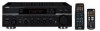
...k A-E/CAT.h w e f DISPLAY ALL PRESET/CH PRESET CAT. Design and specifications are used to production. Remote control Zone 2 remote control Power cable POWER POWER TV AV STANDBY POWER CD MD/TAPE TUNER XM DVD DTV/CBL VCR PHONO REC DISC SKIP TV CODE SET SPEAKERS A B SLEEP VOL CH VOLUME MUTE INPUT 1 ... antenna Indoor FM antenna (Europe and Australia models) Batteries (x2) (AAA, R03, UM-4) 2 SUPPLIED ACCESSORIES Please check that you received all of the buttons on the remote controls. MUTE lA-E/CAT. RETURN MEMORY PRESET/CH MENU SRCH MODE A-E/CAT. In case the...
...k A-E/CAT.h w e f DISPLAY ALL PRESET/CH PRESET CAT. Design and specifications are used to production. Remote control Zone 2 remote control Power cable POWER POWER TV AV STANDBY POWER CD MD/TAPE TUNER XM DVD DTV/CBL VCR PHONO REC DISC SKIP TV CODE SET SPEAKERS A B SLEEP VOL CH VOLUME MUTE INPUT 1 ... antenna Indoor FM antenna (Europe and Australia models) Batteries (x2) (AAA, R03, UM-4) 2 SUPPLIED ACCESSORIES Please check that you received all of the buttons on the remote controls. MUTE lA-E/CAT. RETURN MEMORY PRESET/CH MENU SRCH MODE A-E/CAT. In case the...
Owners Manual
Page 7
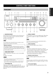
... 2 is pressed (see pages 9, 39 and 40). 7 Front panel display Shows information about the operational status of Zone 2. Select the input source of power to receive infrared signals from the remote control. Notes • This button is operational only when Zone 2 is selected as the input source of Zone 2. 6 Remote... this unit or sets it outward to the OFF position to turn on Main Zone of power to turn off , this unit. Note Switch the remote control ID between ID1 and ID2 when using multiple YAMAHA receivers or amplifiers (see page 18). 4 ZONE 2 ON/OFF Turns on Zone 2 or set it ...
... 2 is pressed (see pages 9, 39 and 40). 7 Front panel display Shows information about the operational status of Zone 2. Select the input source of power to receive infrared signals from the remote control. Notes • This button is operational only when Zone 2 is selected as the input source of Zone 2. 6 Remote... this unit or sets it outward to the OFF position to turn on Main Zone of power to turn off , this unit. Note Switch the remote control ID between ID1 and ID2 when using multiple YAMAHA receivers or amplifiers (see page 18). 4 ZONE 2 ON/OFF Turns on Zone 2 or set it ...
Owners Manual
Page 10
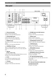
...is a control expansion jack. See page 41 for connection information. 3 REMOTE jacks These jacks are used to your nearest authorized YAMAHA dealer or service center about this jack. 5 XM jack (U.S.A. See page 14 for details. B SPEAKERS terminals Connect speakers. ... other audio and video components. See page 12 for details. 6 C IMPEDANCE SELECTOR switch Switches the impedance setting. model) AC IN IMPEDANCE SELECTOR SET BEFORE POWER ON SELECTEUR D'IMPEDANCE A A OR B: 4ΩMIN. /SPEAKER A+B: 8ΩMIN. /SPEAKER A OR B: 6ΩMIN. /SPEAKER B AC OUTLETS...
...is a control expansion jack. See page 41 for connection information. 3 REMOTE jacks These jacks are used to your nearest authorized YAMAHA dealer or service center about this jack. 5 XM jack (U.S.A. See page 14 for details. B SPEAKERS terminals Connect speakers. ... other audio and video components. See page 12 for details. 6 C IMPEDANCE SELECTOR switch Switches the impedance setting. model) AC IN IMPEDANCE SELECTOR SET BEFORE POWER ON SELECTEUR D'IMPEDANCE A A OR B: 4ΩMIN. /SPEAKER A+B: 8ΩMIN. /SPEAKER A OR B: 6ΩMIN. /SPEAKER B AC OUTLETS...
Owners Manual
Page 11
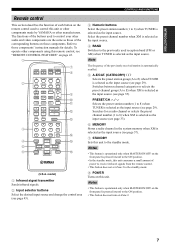
... channel in the system memory when XM is selected as the input source (see "REMOTE CONTROL FEATURES" on page 43. 1 POWER POWER TV AV STANDBY POWER 7 8 2 CD MD/TAPE TUNER XM DVD DTV/CBL VCR PHONO 3 4 5 6 REC DISC SKIP TV CODE SET ... to the ON position. • In the standby mode, this unit consumes a small amount of the previously received station is automatically recalled. 5 A-E/CAT. (CATEGORY) j / i Selects the preset station group (A to E)...or other components made by YAMAHA or other components using this remote control, see page 37). 7 STANDBY Sets this unit.
... channel in the system memory when XM is selected as the input source (see "REMOTE CONTROL FEATURES" on page 43. 1 POWER POWER TV AV STANDBY POWER 7 8 2 CD MD/TAPE TUNER XM DVD DTV/CBL VCR PHONO 3 4 5 6 REC DISC SKIP TV CODE SET ... to the ON position. • In the standby mode, this unit consumes a small amount of the previously received station is automatically recalled. 5 A-E/CAT. (CATEGORY) j / i Selects the preset station group (A to E)...or other components made by YAMAHA or other components using this remote control, see page 37). 7 STANDBY Sets this unit.

Owners Manual
Page 13
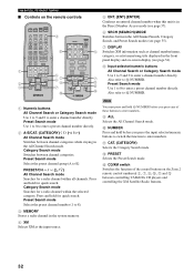
...6 p C NUMBER D (U.S.A. PRESET/CH k / n Searches for a radio channel or selects the preset channel number (1 to control the XM Satellite Radio features and YAMAHA CD players. 1 ZONE 2 POWER 7 CD PHONO TUNER STANDBY 1 2 3 8 MD/TAPE VCR DTV/CBL 2 4 5 6 ENT 9 DVD XM 7 8 9 0 u + 3 PRESET VOLUME...2. PRESET Selects the Preset Search mode. A-E/CAT. (CATEGORY) l / h Switches between ID1 and ID2 (see page 40). 7 POWER Turns on the Zone 2 remote control used to control Zone 2. INTRODUCTION CONTROLS AND FUNCTIONS Zone 2 remote control This section describes the ...
...6 p C NUMBER D (U.S.A. PRESET/CH k / n Searches for a radio channel or selects the preset channel number (1 to control the XM Satellite Radio features and YAMAHA CD players. 1 ZONE 2 POWER 7 CD PHONO TUNER STANDBY 1 2 3 8 MD/TAPE VCR DTV/CBL 2 4 5 6 ENT 9 DVD XM 7 8 9 0 u + 3 PRESET VOLUME...2. PRESET Selects the Preset Search mode. A-E/CAT. (CATEGORY) l / h Switches between ID1 and ID2 (see page 40). 7 POWER Turns on the Zone 2 remote control used to control Zone 2. INTRODUCTION CONTROLS AND FUNCTIONS Zone 2 remote control This section describes the ...

Owners Manual
Page 15
...1 2 2 3 3 4 -5 4 5+ BALANCE 0 1 1 2 2 3 3 4 L5 4 5R 7 8 LOUDNESS FLAT 1 2 -30dB 10 3 9 4 8 5 7 6 VOLUME 30 30 Approximately 6 m (19.7 ft) POWER POWER TV AV STANDBY POWER CD MD/TAPE TUNER XM DVD DTV/CBL VCR PHONO REC DISC SKIP TV VOL CH AUDIO SPEAKERS A B SLEEP VOLUME MUTE INPUT 1 2 5 6 9 0 MUTE 3 4 7 8 10...Do not expose the remote control sensor to the polarity markings (+ and -) on the infrared signal receiver in Zone 2 during operation. INTRODUCTION CONTROLS AND FUNCTIONS Installing batteries in the remote controls ■ Notes...
...1 2 2 3 3 4 -5 4 5+ BALANCE 0 1 1 2 2 3 3 4 L5 4 5R 7 8 LOUDNESS FLAT 1 2 -30dB 10 3 9 4 8 5 7 6 VOLUME 30 30 Approximately 6 m (19.7 ft) POWER POWER TV AV STANDBY POWER CD MD/TAPE TUNER XM DVD DTV/CBL VCR PHONO REC DISC SKIP TV VOL CH AUDIO SPEAKERS A B SLEEP VOLUME MUTE INPUT 1 2 5 6 9 0 MUTE 3 4 7 8 10...Do not expose the remote control sensor to the polarity markings (+ and -) on the infrared signal receiver in Zone 2 during operation. INTRODUCTION CONTROLS AND FUNCTIONS Installing batteries in the remote controls ■ Notes...

Owners Manual
Page 16
... the end of this unit is incorrect, the sound will be connected to this unit. CAUTION • Before connecting the speakers, make sure that the power of the corresponding terminal. Connect the striped, grooved or ridged cable to secure the wire. Red: positive (+) Black: negative (-) 10 mm (3/8 in the side of...
... the end of this unit is incorrect, the sound will be connected to this unit. CAUTION • Before connecting the speakers, make sure that the power of the corresponding terminal. Connect the striped, grooved or ridged cable to secure the wire. Red: positive (+) Black: negative (-) 10 mm (3/8 in the side of...

Owners Manual
Page 17
... Video out Audio out Video out Connecting audio and video components CONNECTIONS CAUTION • Do not connect this unit or other components to the main power until all connections between components are designed to connect a turntable with a lowoutput MC cartridge, use an in-line boosting transformer or an MC-head amplifier...
... Video out Audio out Video out Connecting audio and video components CONNECTIONS CAUTION • Do not connect this unit or other components to the main power until all connections between components are designed to connect a turntable with a lowoutput MC cartridge, use an in-line boosting transformer or an MC-head amplifier...

Owners Manual
Page 20
... front panel are complete. If removed, no sound will not function except the PHONES jack and the SPEAKERS A/B buttons. The outlets supply power to operate separately as a power amplifier, connect the output jacks of this unit is turned on . AC 110/120/220/230-240 V, 50/60 Hz ■...Use these outlets to this unit must be 6 Ω or higher. These jacks are as a graphic equalizer or a surround-sound processor to connect the power supply cords from these jacks, the VOLUME control of this unit will be connected. In this case, the controls of the speakers in your system...
... front panel are complete. If removed, no sound will not function except the PHONES jack and the SPEAKERS A/B buttons. The outlets supply power to operate separately as a power amplifier, connect the output jacks of this unit is turned on . AC 110/120/220/230-240 V, 50/60 Hz ■...Use these outlets to this unit must be 6 Ω or higher. These jacks are as a graphic equalizer or a surround-sound processor to connect the power supply cords from these jacks, the VOLUME control of this unit will be connected. In this case, the controls of the speakers in your system...

Owners Manual
Page 21
... the standby mode independently (see page 42). Press MAIN ZONE ON/OFF on the front panel or POWER on the remote control to turn off this unit When all connections are complete, turn on the power of this unit. 1 MASTER ON OFF MAIN ZONE ON/OFF SPEAKERS A B INPUT ZONE 2 ON/OFF ZONE... the remote control. Turning on and off this unit. You can turn on Zone 2 or set Main Zone of this unit to turn on the power of this unit turns on again. y While MASTER ON/OFF on the front panel is pressed inward to the ON position, you can set it...
... the standby mode independently (see page 42). Press MAIN ZONE ON/OFF on the front panel or POWER on the remote control to turn off this unit When all connections are complete, turn on the power of this unit. 1 MASTER ON OFF MAIN ZONE ON/OFF SPEAKERS A B INPUT ZONE 2 ON/OFF ZONE... the remote control. Turning on and off this unit. You can turn on Zone 2 or set Main Zone of this unit to turn on the power of this unit turns on again. y While MASTER ON/OFF on the front panel is pressed inward to the ON position, you can set it...

Owners Manual
Page 22
... check the sound output level of the input selector buttons on the remote control) to select speakers A and/or speakers B. INPUT or POWER POWER TV AV STANDBY POWER CD MD/TAPE TUNER XM DVD DTV/CBL VCR PHONO Front panel Remote control 16 20 12 VOLUME 26 8 40 4 60 ∞...or press VOLUME +/- If you play back a CD encoded in DTS. SPEAKERS A B SPEAKERS A or B Front panel Remote control 61 5 6 1 POWER POWER TV AV STANDBY POWER CD MD/TAPE TUNER XM DVD DTV/CBL VCR PHONO REC DISC SKIP TV CODE SET SPEAKERS A B SLEEP VOL CH VOLUME 2 4 4 Notes &#...
... check the sound output level of the input selector buttons on the remote control) to select speakers A and/or speakers B. INPUT or POWER POWER TV AV STANDBY POWER CD MD/TAPE TUNER XM DVD DTV/CBL VCR PHONO Front panel Remote control 16 20 12 VOLUME 26 8 40 4 60 ∞...or press VOLUME +/- If you play back a CD encoded in DTS. SPEAKERS A B SPEAKERS A or B Front panel Remote control 61 5 6 1 POWER POWER TV AV STANDBY POWER CD MD/TAPE TUNER XM DVD DTV/CBL VCR PHONO REC DISC SKIP TV CODE SET SPEAKERS A B SLEEP VOL CH VOLUME 2 4 4 Notes &#...

Owners Manual
Page 24
... sound output level. As a result, the input signals bypass the INPUT selector and the BASS, TREBLE, BALANCE and LOUDNESS controls and then sent to the power amplifier, thus eliminating any volume level, thus compensating for sound imbalance caused by speaker locations or listening room conditions. PURE DIRECT Note If both the...
... sound output level. As a result, the input signals bypass the INPUT selector and the BASS, TREBLE, BALANCE and LOUDNESS controls and then sent to the power amplifier, thus eliminating any volume level, thus compensating for sound imbalance caused by speaker locations or listening room conditions. PURE DIRECT Note If both the...
Owners Manual
Page 26
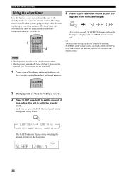
...selector buttons on the remote control to the standby mode after a certain amount of time before this unit is set to the AC OUTLETS. 1 POWER POWER TV AV STANDBY POWER CD MD/TAPE TUNER XM DVD DTV/CBL VCR PHONO REC DISC SKIP TV CODE SET SPEAKERS A B SLEEP VOL CH VOLUME 3 4 Press ...SLEEP repeatedly so that SLEEP OFF appears in the front panel display. SLEEP 22 POWER POWER TV AV STANDBY POWER CD MD/TAPE TUNER XM DVD DTV/CBL VCR PHONO 2 Start playback on the front panel) to set this unit to sleep while this...
...selector buttons on the remote control to the standby mode after a certain amount of time before this unit is set to the AC OUTLETS. 1 POWER POWER TV AV STANDBY POWER CD MD/TAPE TUNER XM DVD DTV/CBL VCR PHONO REC DISC SKIP TV CODE SET SPEAKERS A B SLEEP VOL CH VOLUME 3 4 Press ...SLEEP repeatedly so that SLEEP OFF appears in the front panel display. SLEEP 22 POWER POWER TV AV STANDBY POWER CD MD/TAPE TUNER XM DVD DTV/CBL VCR PHONO 2 Start playback on the front panel) to set this unit to sleep while this...
Owners Manual
Page 36
...to E). Note You must press and hold for a radio channel within all channels. TV AV 6 SRCH (SEARCH) MODE CD MD/TAPE TUNER XM DVD DTV/CBL VCR PHONO REC DISC SKIP ...CODE SET SPEAKERS A B SLEEP 4 Switches between controlling YAMAHA CD players and controlling the XM Satellite Radio features. 32 Also refer to 8). 3 MEMORY... modes (see page 34). Category Search mode Switches between channel categories while staying in SYSTEM POWER POWER STANDBY POWER the Direct Number Access mode (see page 37). C CD/XM switch Switches the function ...
...to E). Note You must press and hold for a radio channel within all channels. TV AV 6 SRCH (SEARCH) MODE CD MD/TAPE TUNER XM DVD DTV/CBL VCR PHONO REC DISC SKIP ...CODE SET SPEAKERS A B SLEEP 4 Switches between controlling YAMAHA CD players and controlling the XM Satellite Radio features. 32 Also refer to 8). 3 MEMORY... modes (see page 34). Category Search mode Switches between channel categories while staying in SYSTEM POWER POWER STANDBY POWER the Direct Number Access mode (see page 37). C CD/XM switch Switches the function ...

Owners Manual
Page 43
...-30dB 10 3 9 4 8 5 7 6 PURE DIRECT CD DIRECT AMP VOLUME 16 20 12 26 8 40 4 60 ∞ -dB 2 0 2,4 3 1 Press MASTER ON/OFF on the power of your area. A/B/C/D/E CATEGORY While holding down, press MASTER ON OFF ADVANCED OPERATION 39 Choices: ID1, ID2 • Select ID1 to operate this unit. Factory...on the front panel and then press MASTER ON/OFF inward to the OFF position. Remote REMOTE Use to the factory presets. The power of this unit is displayed in the front panel display. Choices: AM10/FM100, AM9/FM50 • North, Central and South America...
...-30dB 10 3 9 4 8 5 7 6 PURE DIRECT CD DIRECT AMP VOLUME 16 20 12 26 8 40 4 60 ∞ -dB 2 0 2,4 3 1 Press MASTER ON/OFF on the power of your area. A/B/C/D/E CATEGORY While holding down, press MASTER ON OFF ADVANCED OPERATION 39 Choices: ID1, ID2 • Select ID1 to operate this unit. Factory...on the front panel and then press MASTER ON/OFF inward to the OFF position. Remote REMOTE Use to the factory presets. The power of this unit is displayed in the front panel display. Choices: AM10/FM100, AM9/FM50 • North, Central and South America...

Owners Manual
Page 44
...using an alternative code. DISPLAY Remote control ID* (this unit's setting) ID1 ID2 (default setting) Function To operate this unit using multiple YAMAHA receivers or amplifiers with the remote control by switching the remote control ID. 1 Press and hold CODE SET on the remote control and then press... TUNER on the remote control. 4 Press A/B/C/D/E on the remote control to operate this unit separately. CODE SET MENU POWER POWER TV AV STANDBY POWER CD MD/TAPE TUNER XM DVD DTV/CBL VCR PHONO 2 While holding down CODE SET on the remote control, use the numeric buttons...
...using an alternative code. DISPLAY Remote control ID* (this unit's setting) ID1 ID2 (default setting) Function To operate this unit using multiple YAMAHA receivers or amplifiers with the remote control by switching the remote control ID. 1 Press and hold CODE SET on the remote control and then press... TUNER on the remote control. 4 Press A/B/C/D/E on the remote control to operate this unit separately. CODE SET MENU POWER POWER TV AV STANDBY POWER CD MD/TAPE TUNER XM DVD DTV/CBL VCR PHONO 2 While holding down CODE SET on the remote control, use the numeric buttons...


