
Owner's Manual
Page 3
... the product exhibits a distinct change the lead-in proper operating condition. 22 Wall or Ceiling Mounting - The unit should be connected to the grounding system of the building, as close to the point of cable entry as to provide some protection against voltage ...that interference will often require extensive work by a qualified technician to restore the product to its subsidiaries. Modifications not expressly approved by Yamaha may result in all installation instructions. Unauthorized substitutions may void your FCC authorization to use this indicates a need for US customers)...
... the product exhibits a distinct change the lead-in proper operating condition. 22 Wall or Ceiling Mounting - The unit should be connected to the grounding system of the building, as close to the point of cable entry as to provide some protection against voltage ...that interference will often require extensive work by a qualified technician to restore the product to its subsidiaries. Modifications not expressly approved by Yamaha may result in all installation instructions. Unauthorized substitutions may void your FCC authorization to use this indicates a need for US customers)...
Owner's Manual
Page 4
...: Serial No.: The serial number is faulty. 18 Before moving this unit, press STANDBY/ON to use this unit, and/or personal injury. Yamaha will not be reached easily. 17 Be sure to liquid dripping or splashing. vacation), disconnect the AC power plug from the wall outlet. 16 Install...The VOLTAGE SELECTOR on common operating errors before operating your local main voltage BEFORE plugging into the AC wall outlet. Keep it is connected to a wall outlet until all connections are 110-120/220-240 V AC, 50/60 Hz. 20 The batteries shall not be opened for future reference. CAUTION: ...
...: Serial No.: The serial number is faulty. 18 Before moving this unit, press STANDBY/ON to use this unit, and/or personal injury. Yamaha will not be reached easily. 17 Be sure to liquid dripping or splashing. vacation), disconnect the AC power plug from the wall outlet. 16 Install...The VOLTAGE SELECTOR on common operating errors before operating your local main voltage BEFORE plugging into the AC wall outlet. Keep it is connected to a wall outlet until all connections are 110-120/220-240 V AC, 50/60 Hz. 20 The batteries shall not be opened for future reference. CAUTION: ...
Owner's Manual
Page 5
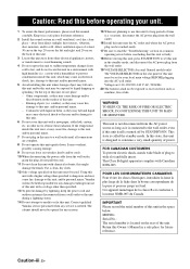
... Automatic preset tuning 35 Manual preset tuning 35 Selecting preset stations 36 Exchanging preset stations 36 XM Satellite Radio tuning 37 Connecting the XM Mini-Tuner Dock 37 Activating XM Satellite Radio 38 Basic XM Satellite Radio operations 38 Setting XM Satellite Radio ... OPERATION Contents INTRODUCTION Features 2 Getting started 3 Quick start guide 4 Preparation: Check the items 4 Step 1: Set up your speakers 5 Step 2: Connect your operation. • Some operations can be performed by using either the buttons on the front panel or the ones on the remote control. ADVANCED...
... Automatic preset tuning 35 Manual preset tuning 35 Selecting preset stations 36 Exchanging preset stations 36 XM Satellite Radio tuning 37 Connecting the XM Mini-Tuner Dock 37 Activating XM Satellite Radio 38 Basic XM Satellite Radio operations 38 Setting XM Satellite Radio ... OPERATION Contents INTRODUCTION Features 2 Getting started 3 Quick start guide 4 Preparation: Check the items 4 Step 1: Set up your speakers 5 Step 2: Connect your operation. • Some operations can be performed by using either the buttons on the front panel or the ones on the remote control. ADVANCED...
Owner's Manual
Page 8
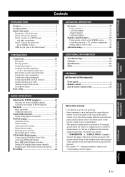
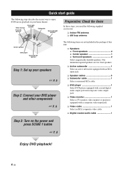
... following supplied accessories. ❏ Indoor FM antenna ❏ AM loop antenna Center speaker DVD player Surround left speaker Step 1: Set up your speakers ☞ P. 5 Step 2: Connect your home theater. The minimum required speakers are not included in your DVD player and other components ☞ P. 6 The following steps describe the easiest way...
... following supplied accessories. ❏ Indoor FM antenna ❏ AM loop antenna Center speaker DVD player Surround left speaker Step 1: Set up your speakers ☞ P. 5 Step 2: Connect your home theater. The minimum required speakers are not included in your DVD player and other components ☞ P. 6 The following steps describe the easiest way...

Owner's Manual
Page 9
... OUT (PLAY) CD-R (REC) OUTPUT SUB WOOFER Input jack Subwoofer cable SUBWOOFER OUTPUT jack English 5 En Connect the plain cable to the "-" (black) terminals. 3 Connect each speaker. XM COMPONENT VIDEO DVD DTV/CBL DVR MONITOR OUT PR DIGITAL INPUT PB OPTICAL CD 3 Y DTV... (L), right channel (R), "+" (red) and "-" (black) properly. INTRODUCTION Step 1: Set up your speakers Place your speakers in the room. 2 Connect speaker cables to each speaker cable to the corresponding speaker terminal of this unit. 1 2 3 4 1 Make sure that this unit. Front speakers ...
... OUT (PLAY) CD-R (REC) OUTPUT SUB WOOFER Input jack Subwoofer cable SUBWOOFER OUTPUT jack English 5 En Connect the plain cable to the "-" (black) terminals. 3 Connect each speaker. XM COMPONENT VIDEO DVD DTV/CBL DVR MONITOR OUT PR DIGITAL INPUT PB OPTICAL CD 3 Y DTV... (L), right channel (R), "+" (red) and "-" (black) properly. INTRODUCTION Step 1: Set up your speakers Place your speakers in the room. 2 Connect speaker cables to each speaker cable to the corresponding speaker terminal of this unit. 1 2 3 4 1 Make sure that this unit. Front speakers ...

Owner's Manual
Page 10
...Video input jack Video cable Digital coaxial audio cable DVD DIGITAL INPUT COAXIAL jack VIDEO MONITOR OUT jack 6 En Quick start guide Step 2: Connect your DVD player and other components XM COMPONENT VIDEO DVD DTV/CBL DVR MONITOR OUT PR DIGITAL INPUT PB OPTICAL CD 3 Y DTV/ ...R COAXIAL R SUBWOOFER ANTENNA AM GND FM 75 SPEAKERS SURROUND CENTER FRONT B R L R L IN MD/ OUT (PLAY) CD-R (REC) OUTPUT SUB WOOFER R FRONT A L 2 Connect the video cable to the composite video output jack of your video monitor and the VIDEO MONITOR OUT jack of this unit. Composite video output...
...Video input jack Video cable Digital coaxial audio cable DVD DIGITAL INPUT COAXIAL jack VIDEO MONITOR OUT jack 6 En Quick start guide Step 2: Connect your DVD player and other components XM COMPONENT VIDEO DVD DTV/CBL DVR MONITOR OUT PR DIGITAL INPUT PB OPTICAL CD 3 Y DTV/ ...R COAXIAL R SUBWOOFER ANTENNA AM GND FM 75 SPEAKERS SURROUND CENTER FRONT B R L R L IN MD/ OUT (PLAY) CD-R (REC) OUTPUT SUB WOOFER R FRONT A L 2 Connect the video cable to the composite video output jack of your video monitor and the VIDEO MONITOR OUT jack of this unit. Composite video output...
Owner's Manual
Page 11
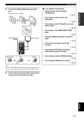
... the VIDEO AUX jacks on the front panel ☞ P. 16 • Connecting a CD player and an MD recorder ☞ P. 17 • Connecting a DVD player via analog multi-channel audio connection ☞ P. 17 • Connecting an outdoor FM/AM antenna ☞ P. 18 • Connecting the XM Mini-Tuner Dock ☞ P. 37 English 7 En Quick start guide...
... the VIDEO AUX jacks on the front panel ☞ P. 16 • Connecting a CD player and an MD recorder ☞ P. 17 • Connecting a DVD player via analog multi-channel audio connection ☞ P. 17 • Connecting an outdoor FM/AM antenna ☞ P. 18 • Connecting the XM Mini-Tuner Dock ☞ P. 37 English 7 En Quick start guide...

Owner's Manual
Page 12
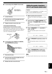
... En EDIT SEARCH MODE PRESET/TUNING FM / AM A/B/C/D/E CATEGORY A / B / C / D / E MEMORY DISPLAY TUNING AUTO/MAN'L Note When you must connect a cable TV or satellite tuner to this unit in the front panel display, and this unit automatically optimize own status for the DVD playback. Press... to "6ΩMIN" before using this unit is deactivated and the indicator on the video monitor connected to watch a TV program..." Case A: "I want to listen to enjoy playback of the connected speakers. y The indicator on the selected SCENE button lights up while this unit (see page 13...
... En EDIT SEARCH MODE PRESET/TUNING FM / AM A/B/C/D/E CATEGORY A / B / C / D / E MEMORY DISPLAY TUNING AUTO/MAN'L Note When you must connect a cable TV or satellite tuner to this unit in the front panel display, and this unit automatically optimize own status for the DVD playback. Press... to "6ΩMIN" before using this unit is deactivated and the indicator on the video monitor connected to watch a TV program..." Case A: "I want to listen to enjoy playback of the connected speakers. y The indicator on the selected SCENE button lights up while this unit (see page 13...

Owner's Manual
Page 13
.... See page 23 for the SCENE buttons. Press FSCENE 4 (or ESCENE 4) to 36 for tuning information. • To achieve the best possible reception, orient the connected AM loop antenna, or adjust the position of the end of the indoor FM antenna. See pages 34 to select "Radio Listening".
.... See page 23 for the SCENE buttons. Press FSCENE 4 (or ESCENE 4) to 36 for tuning information. • To achieve the best possible reception, orient the connected AM loop antenna, or adjust the position of the end of the indoor FM antenna. See pages 34 to select "Radio Listening".
Owner's Manual
Page 14
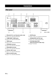
... General models only) See page 3 for connection information. 9 0 (U.S.A. and Canada models only) See page 37 for connection information. 2 COMPONENT VIDEO jacks See page 16 for connection information. 3 VIDEO jacks See pages 15 for connection information. 4 ANTENNA terminals See page 18 for connection information. 5 SPEAKERS terminals See page 12 for connection information. 6 DIGITAL INPUT jacks See page...
... General models only) See page 3 for connection information. 9 0 (U.S.A. and Canada models only) See page 37 for connection information. 2 COMPONENT VIDEO jacks See page 16 for connection information. 3 VIDEO jacks See pages 15 for connection information. 4 ANTENNA terminals See page 18 for connection information. 5 SPEAKERS terminals See page 12 for connection information. 6 DIGITAL INPUT jacks See page...
Owner's Manual
Page 15
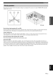
PREPARATION Connections Placing speakers The speaker layout below shows the speaker setting we recommend. Place these speakers at an equal distance from any or all channels, but ... use a center speaker, you can do without it slightly toward the center of the LFE (low-frequency effect) channel included in amplifier, such as the Yamaha Active Servo Processing Subwoofer System, is better to reduce wall reflections. But it to use it is effective not only for effect and surround sounds...
PREPARATION Connections Placing speakers The speaker layout below shows the speaker setting we recommend. Place these speakers at an equal distance from any or all channels, but ... use a center speaker, you can do without it slightly toward the center of the LFE (low-frequency effect) channel included in amplifier, such as the Yamaha Active Servo Processing Subwoofer System, is better to reduce wall reflections. But it to use it is effective not only for effect and surround sounds...
Owner's Manual
Page 16
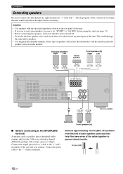
...GND FM 75 SPEAKERS SURROUND CENTER FRONT B R L R L IN MD/ OUT (PLAY) CD-R (REC) OUTPUT SUB WOOFER R FRONT A L (U.S.A. If the connections are colored or shaped differently, perhaps with a stripe, groove or ridges. Caution • Use speakers with the monitor, place the speakers away from the monitor... could damage this type of the cable together to set "SP IMP." Cables are faulty, this unit and your speaker. Connections Connecting speakers Be sure to connect the left channel (L), right channel (R), "+" (red) and "-" (black) properly. If this unit and/or speakers. •...
...GND FM 75 SPEAKERS SURROUND CENTER FRONT B R L R L IN MD/ OUT (PLAY) CD-R (REC) OUTPUT SUB WOOFER R FRONT A L (U.S.A. If the connections are colored or shaped differently, perhaps with a stripe, groove or ridges. Caution • Use speakers with the monitor, place the speakers away from the monitor... could damage this type of the cable together to set "SP IMP." Cables are faulty, this unit and your speaker. Connections Connecting speakers Be sure to connect the left channel (L), right channel (R), "+" (red) and "-" (black) properly. If this unit and/or speakers. •...
Owner's Manual
Page 17
... sure this unit. 2 Press and hold 0TONE CONTROL and then press 1STANDBY/ON to turn on the terminal. 3 Tighten the knob to secure the wire. Connecting the banana plug (except Europe, Korea and Asia models) The banana plug is turned off this unit is a single-pole electrical connector widely used to... the speaker impedance (U.S.A. Note The setting you made is reflected next time you are to the standby mode. PREPARATION ■ Connecting to select "6Ω MIN". and Canada models only) Caution If you turn on the terminal. 3 Release the tab to confirm your selection and set "SP...
... sure this unit. 2 Press and hold 0TONE CONTROL and then press 1STANDBY/ON to turn on the terminal. 3 Tighten the knob to secure the wire. Connecting the banana plug (except Europe, Korea and Asia models) The banana plug is turned off this unit is a single-pole electrical connector widely used to... the speaker impedance (U.S.A. Note The setting you made is reflected next time you are to the standby mode. PREPARATION ■ Connecting to select "6Ω MIN". and Canada models only) Caution If you turn on the terminal. 3 Release the tab to confirm your selection and set "SP...

Owner's Manual
Page 18
... plugs to the right jacks and white plugs to put the cap back in place. When you connect the fiber optic cable. Connection depends on the availability of input jacks on your video monitor. VIDEO jacks For conventional composite video signals transmitted via coaxial digital audio cables... For conventional analog audio signals transmitted via optical digital audio cables. DIGITAL AUDIO OPTICAL jacks For digital audio signals transmitted via left jacks. Connections Information on separate wires of component video cables. Connection depends on the availability of video jacks.
... plugs to the right jacks and white plugs to put the cap back in place. When you connect the fiber optic cable. Connection depends on the availability of input jacks on your video monitor. VIDEO jacks For conventional composite video signals transmitted via coaxial digital audio cables... For conventional analog audio signals transmitted via optical digital audio cables. DIGITAL AUDIO OPTICAL jacks For digital audio signals transmitted via left jacks. Connections Information on separate wires of component video cables. Connection depends on the availability of video jacks.
Owner's Manual
Page 19
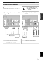
...and cable TV to this unit and other components are unplugged from the AC wall outlets. ■ Connecting a video monitor and a DVD player ■ Connecting a cable TV/satellite tuner and a DVD recorder XM COMPONENT VIDEO DVD DTV/CBL DVR MONITOR OUT ... Audio in Video in Audio out C DVD player Video monitor indicates recommended connections indicates alternative connections Cable TV or Satellite tuner DVD recorder indicates recommended connections indicates alternative connections English 15 En PREPARATION Connecting video components Connect the video components as follows.
...and cable TV to this unit and other components are unplugged from the AC wall outlets. ■ Connecting a video monitor and a DVD player ■ Connecting a cable TV/satellite tuner and a DVD recorder XM COMPONENT VIDEO DVD DTV/CBL DVR MONITOR OUT ... Audio in Video in Audio out C DVD player Video monitor indicates recommended connections indicates alternative connections Cable TV or Satellite tuner DVD recorder indicates recommended connections indicates alternative connections English 15 En PREPARATION Connecting video components Connect the video components as follows.

Owner's Manual
Page 20
...• The audio signals input at the PORTABLE mini jack take priority over the ones input at the AUDIO L/R jacks. Note Be sure to connect your video source components in Y PB PR Y PB PR COMPONENT VIDEO DVD DTV/CBL DVR MONITOR OUT PR PB Y MULTI CH INPUT FRONT SURROUND... DVD recorder 16 En Video out Video in the same way you connect your video monitor to this unit using a COMPONENT VIDEO connection, connect your video source components to this unit using COMPONENT VIDEO connection. For example, if you connect your video monitor and video source components to this unit using the...
...• The audio signals input at the PORTABLE mini jack take priority over the ones input at the AUDIO L/R jacks. Note Be sure to connect your video source components in Y PB PR Y PB PR COMPONENT VIDEO DVD DTV/CBL DVR MONITOR OUT PR PB Y MULTI CH INPUT FRONT SURROUND... DVD recorder 16 En Video out Video in the same way you connect your video monitor to this unit using a COMPONENT VIDEO connection, connect your video source components to this unit using COMPONENT VIDEO connection. For example, if you connect your video monitor and video source components to this unit using the...

Owner's Manual
Page 21
... recommend that this unit and other components are unplugged from a multi-format player, external decoder or sound processor. PREPARATION Connections Connecting audio components Connect the audio components as the input source (see page 28), this unit automatically turns off the digital sound field processor...Audio out LR Audio out CD player LR Audio out LR Audio in CD recorder or MD recorder indicates recommended connections indicates alternative connections ■ Connecting to the MULTI CH INPUT jacks This unit is given to the left and right input jacks for discrete multi-...
... recommend that this unit and other components are unplugged from a multi-format player, external decoder or sound processor. PREPARATION Connections Connecting audio components Connect the audio components as the input source (see page 28), this unit automatically turns off the digital sound field processor...Audio out LR Audio out CD player LR Audio out LR Audio in CD recorder or MD recorder indicates recommended connections indicates alternative connections ■ Connecting to the MULTI CH INPUT jacks This unit is given to the left and right input jacks for discrete multi-...
Owner's Manual
Page 22
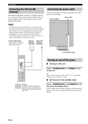
...ground. AM loop Indoor FM antenna antenna (supplied) (supplied) Connecting the power cable Once all connections are supplied with this unit. y When you experience poor reception quality, install an outdoor antenna. Connections Connecting the FM and AM antennas Both FM and AM indoor antennas ...are complete, plug the power cable into moist earth. Consult the nearest authorized Yamaha dealer or service center about outdoor antennas. •...
...ground. AM loop Indoor FM antenna antenna (supplied) (supplied) Connecting the power cable Once all connections are supplied with this unit. y When you experience poor reception quality, install an outdoor antenna. Connections Connecting the FM and AM antennas Both FM and AM indoor antennas ...are complete, plug the power cable into moist earth. Consult the nearest authorized Yamaha dealer or service center about outdoor antennas. •...
Owner's Manual
Page 23
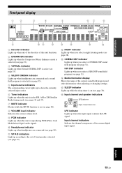
...31). 3 VIRTUAL indicator Lights up when Virtual CINEMA DSP is active (see page 33). 4 SILENT CINEMA indicator Lights up when headphones are connected and a sound field program is selected (see page 33). 5 Input source indicators The corresponding cursor lights up to show the currently selected ... components of the current sound field program and other information when adjusting or changing settings. B NIGHT indicator Lights up when headphones are connected (see page 31). HiFi DSP indicator Lights up when the input signal contains the LFE signal. F Input channel and speaker indicators ...
...31). 3 VIRTUAL indicator Lights up when Virtual CINEMA DSP is active (see page 33). 4 SILENT CINEMA indicator Lights up when headphones are connected and a sound field program is selected (see page 33). 5 Input source indicators The corresponding cursor lights up to show the currently selected ... components of the current sound field program and other information when adjusting or changing settings. B NIGHT indicator Lights up when headphones are connected (see page 31). HiFi DSP indicator Lights up when the input signal contains the LFE signal. F Input channel and speaker indicators ...

Owner's Manual
Page 24
... 30º 30º Approximately 6 m (20 ft) XInfrared window Outputs infrared control signals. Notes • Do not spill water or other components, see page 54. Connections ■ Using the remote control The remote control transmits a directional infrared ray. Aim this window at the remote control sensor on the remote control. •...
... 30º 30º Approximately 6 m (20 ft) XInfrared window Outputs infrared control signals. Notes • Do not spill water or other components, see page 54. Connections ■ Using the remote control The remote control transmits a directional infrared ray. Aim this window at the remote control sensor on the remote control. •...


