Owners Manual
Page 2
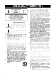
... personnel. 19 Damage Requiring Service - Unplug this product near water - in a fire or electric shock. The product may fall into such power lines or circuits. Use only with them , paying particular attention to the operating instructions. 12 Grounding or Polarization - If you are not ...- Do not use this product from the wall outlet and refer servicing to qualified service personnel under the following conditions: a) When the power-supply cord or plug is a safety feature. Do not use instructions should still fail to fit, contact your electrician to dangerous voltage ...
... personnel. 19 Damage Requiring Service - Unplug this product near water - in a fire or electric shock. The product may fall into such power lines or circuits. Use only with them , paying particular attention to the operating instructions. 12 Grounding or Polarization - If you are not ...- Do not use this product from the wall outlet and refer servicing to qualified service personnel under the following conditions: a) When the power-supply cord or plug is a safety feature. Do not use instructions should still fail to fit, contact your electrician to dangerous voltage ...
Owners Manual
Page 3
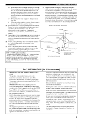
...NATIONAL ELECTRICAL CODE ANTENNA LEAD IN WIRE ANTENNA DISCHARGE UNIT (NEC SECTION 810-20) GROUNDING CONDUCTORS (NEC SECTION 810-21) GROUND CLAMPS POWER SERVICE GROUNDING ELECTRODE SYSTEM (NEC ART 250. Modifications not expressly approved by the FCC, to use of this product in a residential ...be sure the antenna or cable system is in all installation instructions. Failure to follow instructions could void your authority, granted by Yamaha may result in to provide some protection against voltage surges and built-up static charges. Upon completion of the National Electrical Code...
...NATIONAL ELECTRICAL CODE ANTENNA LEAD IN WIRE ANTENNA DISCHARGE UNIT (NEC SECTION 810-20) GROUNDING CONDUCTORS (NEC SECTION 810-21) GROUND CLAMPS POWER SERVICE GROUNDING ELECTRODE SYSTEM (NEC ART 250. Modifications not expressly approved by the FCC, to use of this product in a residential ...be sure the antenna or cable system is in all installation instructions. Failure to follow instructions could void your authority, granted by Yamaha may result in to provide some protection against voltage surges and built-up static charges. Upon completion of the National Electrical Code...
Owners Manual
Page 4
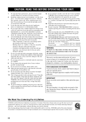
...AC power source as long as they may fall onto this unit and/or this unit may cause fire, damage to wide slot and fully insert. It may overheat, possibly causing damage. 9 Do not use force on the rear panel of your sensitive hearing. Contact qualified YAMAHA service... space below. In this state, this Owner's Manual in a well ventilated, cool, dry, clean place - We Want You Listening For A Lifetime YAMAHA and the Electronic Industries Association's Consumer Electronics Group want you to avoid prolonged exposure from cold to obstruct heat radiation. Use a clean, dry cloth. ...
...AC power source as long as they may fall onto this unit and/or this unit may cause fire, damage to wide slot and fully insert. It may overheat, possibly causing damage. 9 Do not use force on the rear panel of your sensitive hearing. Contact qualified YAMAHA service... space below. In this state, this Owner's Manual in a well ventilated, cool, dry, clean place - We Want You Listening For A Lifetime YAMAHA and the Electronic Industries Association's Consumer Electronics Group want you to avoid prolonged exposure from cold to obstruct heat radiation. Use a clean, dry cloth. ...
Owners Manual
Page 5
... player or an external decoder 22 Connecting a game console, a video camera or a portable audio player........... 22 Connecting the FM and AM antennas 23 Connecting the power cable 24 Setting the speaker impedance 25 Turning on this unit or setting it to the standby mode 26 BASIC SETUP 27 BASIC OPERATION PLAYBACK...
... player or an external decoder 22 Connecting a game console, a video camera or a portable audio player........... 22 Connecting the FM and AM antennas 23 Connecting the power cable 24 Setting the speaker impedance 25 Turning on this unit or setting it to the standby mode 26 BASIC SETUP 27 BASIC OPERATION PLAYBACK...
Owners Manual
Page 6
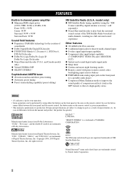
...and the remote control, the button name on the remote control is given in parentheses. • This manual is a trademark of YAMAHA CORPORATION. Manufactured under license from Digital Theater Systems, Inc. All right reserved. Neural Surround™ name and related logos are trademarks ... ◆ Minimum RMS output power (0.06% THD, 20 Hz to 20 kHz, 8 Ω) Front: 90 W + 90 W Center: 90 W Surround: 90 W + 90 W Surround back: 90 W Sound field features ◆ Proprietary YAMAHA technology for a portable audio player ◆ Compressed Music Enhancer mode to improve the sound quality of...
...and the remote control, the button name on the remote control is given in parentheses. • This manual is a trademark of YAMAHA CORPORATION. Manufactured under license from Digital Theater Systems, Inc. All right reserved. Neural Surround™ name and related logos are trademarks ... ◆ Minimum RMS output power (0.06% THD, 20 Hz to 20 kHz, 8 Ω) Front: 90 W + 90 W Center: 90 W Surround: 90 W + 90 W Surround back: 90 W Sound field features ◆ Proprietary YAMAHA technology for a portable audio player ◆ Compressed Music Enhancer mode to improve the sound quality of...
Owners Manual
Page 7
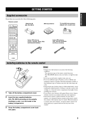
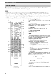
... the inside of the battery compartment. 3 Snap the battery compartment cover back into contact with general house waste; Remote control CODE SET TRANSMIT POWER TV POWER AV STANDBY POWER CD DVD MD CD-R CBL DTV SLEEP XM TUNER MULTI CH IN V-AUX DVR TV VOL TV CH AMP VOLUME SOURCE TV TV MUTE...
... the inside of the battery compartment. 3 Snap the battery compartment cover back into contact with general house waste; Remote control CODE SET TRANSMIT POWER TV POWER AV STANDBY POWER CD DVD MD CD-R CBL DTV SLEEP XM TUNER MULTI CH IN V-AUX DVR TV VOL TV CH AMP VOLUME SOURCE TV TV MUTE...
Owners Manual
Page 8
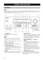
..., and DISPLAY) are operational only when "XM" is selected as the input source. Notes • In the standby mode, this unit consumes a small amount of power in order to receive infrared signals from the remote control (see page 8). 3 PRESET/TUNING, EDIT • Switches the function of PRESET/TUNING/CH l / h between selecting...
..., and DISPLAY) are operational only when "XM" is selected as the input source. Notes • In the standby mode, this unit consumes a small amount of power in order to receive infrared signals from the remote control (see page 8). 3 PRESET/TUNING, EDIT • Switches the function of PRESET/TUNING/CH l / h between selecting...
Owners Manual
Page 10
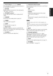
... is selected as the input source. Set the component selector switch to AMP to toggle as the input source. ■ Controlling this 2 CODE SET TRANSMIT POWER POWER STANDBY POWER A unit. 1 Infrared window TV AV B Outputs infrared control signals. Use DIRECT ST. Press this button repeatedly to control this window at the 3 CD DVD...
... is selected as the input source. Set the component selector switch to AMP to toggle as the input source. ■ Controlling this 2 CODE SET TRANSMIT POWER POWER STANDBY POWER A unit. 1 Infrared window TV AV B Outputs infrared control signals. Use DIRECT ST. Press this button repeatedly to control this window at the 3 CD DVD...
Owners Manual
Page 11
B POWER Turns on . E VOLUME +/- Increases or decreases the volume level. SOURCE Operates the component selected with an input selector button (see page 37). Notes • To ...
B POWER Turns on . E VOLUME +/- Increases or decreases the volume level. SOURCE Operates the component selected with an input selector button (see page 37). Notes • To ...
Owners Manual
Page 12
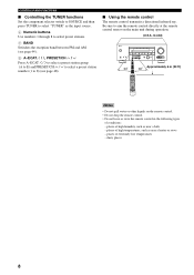
... TUNING MODE DISPLAY AUTO/MAN'L INPUT MULTI CH INPUT VOLUME VIDEO AUX VIDEO L AUDIO R PORTABLE Approximately 6 m (20 ft) 30 30 CODE SET TRANSMIT POWER TV POWER AV STANDBY POWER MD SLEEP CD CD-R XM CBL MULTI CH IN DVD DTV TUNER V-AUX DVR TV VOL TV CH AMP VOLUME SOURCE TV TV MUTE...
... TUNING MODE DISPLAY AUTO/MAN'L INPUT MULTI CH INPUT VOLUME VIDEO AUX VIDEO L AUDIO R PORTABLE Approximately 6 m (20 ft) 30 30 CODE SET TRANSMIT POWER TV POWER AV STANDBY POWER MD SLEEP CD CD-R XM CBL MULTI CH IN DVD DTV TUNER V-AUX DVR TV VOL TV CH AMP VOLUME SOURCE TV TV MUTE...

Owners Manual
Page 15
... and General models only) See page 24 for connection information. 6 XM jack (U.S.A. model only) See page 51 for connection information. 0 AC OUTLET(S) Use to supply power to your other audiovisual components. INTRODUCTION Rear panel 1 2 3 4 56 AUDIO AUDIO MULTI CH INPUT CENTER OUTPUT DIGITAL INPUT XM DVD DTV/CBL DVD IN MD...
... and General models only) See page 24 for connection information. 6 XM jack (U.S.A. model only) See page 51 for connection information. 0 AC OUTLET(S) Use to supply power to your other audiovisual components. INTRODUCTION Rear panel 1 2 3 4 56 AUDIO AUDIO MULTI CH INPUT CENTER OUTPUT DIGITAL INPUT XM DVD DTV/CBL DVD IN MD...
Owners Manual
Page 22
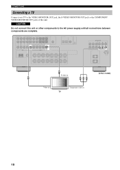
CONNECTIONS Connecting a TV Connect your TV to the VIDEO MONITOR OUT jack, the S VIDEO MONITOR OUT jack or the COMPONENT VIDEO MONITOR OUT jacks of this unit or other components to the AC power supply until all connections between components are complete. model) V Y PB PR Video in Component video in (U.S.A. CAUTION Do not connect this unit. VIDEO MONITOR OUT S VIDEO MONITOR OUT COMPONENT VIDEO Y PB PR MONITOR OUT S S-video in TV 18
CONNECTIONS Connecting a TV Connect your TV to the VIDEO MONITOR OUT jack, the S VIDEO MONITOR OUT jack or the COMPONENT VIDEO MONITOR OUT jacks of this unit or other components to the AC power supply until all connections between components are complete. model) V Y PB PR Video in Component video in (U.S.A. CAUTION Do not connect this unit. VIDEO MONITOR OUT S VIDEO MONITOR OUT COMPONENT VIDEO Y PB PR MONITOR OUT S S-video in TV 18
Owners Manual
Page 23
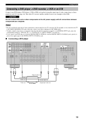
Notes • Be sure to make a digital connection to a component other components to the AC power supply until all connections between components are examples of this unit or other than the default component assigned to each DIGITAL INPUT jack, select the ...
Notes • Be sure to make a digital connection to a component other components to the AC power supply until all connections between components are examples of this unit or other than the default component assigned to each DIGITAL INPUT jack, select the ...
Owners Manual
Page 25
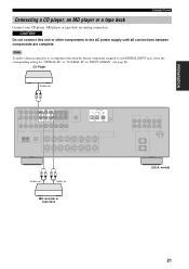
..." or "COAXIAL IN" in MD recorder or tape deck (U.S.A. CAUTION Do not connect this unit or other than the default component assigned to the AC power supply until all connections between components are complete.
..." or "COAXIAL IN" in MD recorder or tape deck (U.S.A. CAUTION Do not connect this unit or other than the default component assigned to the AC power supply until all connections between components are complete.
Owners Manual
Page 26
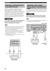
... out Subwoofer out Center out Multi-format player or external decoder 22 Be sure to match the left and right output jacks to the AC power supply until all connections between components are output only from a multi-format player, external decoder, sound processor or pre-amplifier. CAUTION Be sure to the...
... out Subwoofer out Center out Multi-format player or external decoder 22 Be sure to match the left and right output jacks to the AC power supply until all connections between components are output only from a multi-format player, external decoder, sound processor or pre-amplifier. CAUTION Be sure to the...
Owners Manual
Page 28
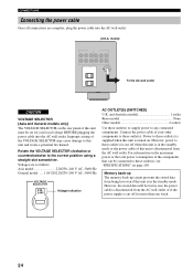
... VOLTAGE SELECTOR 230240V Voltage indication AC OUTLET(S) (SWITCHED) U.K. Rotate the VOLTAGE SELECTOR clockwise or counterclockwise to any connected components. Voltages are complete, plug the power cable into the AC wall outlet. However, the stored data will be lost even if this unit must be connected to these outlet(s) is supplied... when this unit is turned on the rear panel of this unit is in case the power cable is cut off for your other components to these outlet(s) is cut off when this unit is in the standby mode or the...
... VOLTAGE SELECTOR 230240V Voltage indication AC OUTLET(S) (SWITCHED) U.K. Rotate the VOLTAGE SELECTOR clockwise or counterclockwise to any connected components. Voltages are complete, plug the power cable into the AC wall outlet. However, the stored data will be lost even if this unit must be connected to these outlet(s) is supplied... when this unit is turned on the rear panel of this unit is in case the power cable is cut off for your other components to these outlet(s) is cut off when this unit is in the standby mode or the...
Owners Manual
Page 30
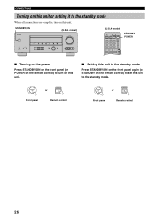
...CBL DTV SLEEP XM TUNER MULTI CH IN V-AUX DVR TV VOL TV CH AMP VOLUME SOURCE TV STANDBY POWER ■ Turning on the power Press STANDBY/ON on the front panel (or POWER on the remote control) to turn on this unit. ■ Setting this unit to the standby mode Press...(or STANDBY on the remote control) to set this unit to the standby mode When all connections are complete, turn on this unit. STANDBY /ON POWER or Front panel Remote control STANDBY /ON STANDBY or Front panel Remote control 26 model) STANDBY /ON PHONES SPEAKERS A B SILENT CINEMA PRESET/TUNING SEARCH...
...CBL DTV SLEEP XM TUNER MULTI CH IN V-AUX DVR TV VOL TV CH AMP VOLUME SOURCE TV STANDBY POWER ■ Turning on the power Press STANDBY/ON on the front panel (or POWER on the remote control) to turn on this unit. ■ Setting this unit to the standby mode Press...(or STANDBY on the remote control) to set this unit to the standby mode When all connections are complete, turn on this unit. STANDBY /ON POWER or Front panel Remote control STANDBY /ON STANDBY or Front panel Remote control 26 model) STANDBY /ON PHONES SPEAKERS A B SILENT CINEMA PRESET/TUNING SEARCH...
Owners Manual
Page 31
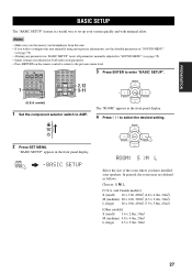
... adjusted in bold under each parameter. • Press RETURN on the remote control to return to the previous menu level. 1 CODE SET TRANSMIT POWER TV POWER AV STANDBY POWER CD DVD MD CD-R CBL DTV SLEEP XM TUNER MULTI CH IN V-AUX DVR TV VOL TV CH AMP VOLUME SOURCE TV (U.S.A. EFFECT SET...
... adjusted in bold under each parameter. • Press RETURN on the remote control to return to the previous menu level. 1 CODE SET TRANSMIT POWER TV POWER AV STANDBY POWER CD DVD MD CD-R CBL DTV SLEEP XM TUNER MULTI CH IN V-AUX DVR TV VOL TV CH AMP VOLUME SOURCE TV (U.S.A. EFFECT SET...
Owners Manual
Page 34
INPUT or CD DVD MD CD-R CBL DTV SLEEP XM TUNER MULTI CH IN 2 6 67 3 2 CODE SET TRANSMIT POWER TV POWER AV STANDBY POWER CD DVD MD CD-R CBL DTV SLEEP XM TUNER MULTI CH IN V-AUX DVR TV VOL TV CH AMP VOLUME SOURCE TV TV MUTE TV ...
INPUT or CD DVD MD CD-R CBL DTV SLEEP XM TUNER MULTI CH IN 2 6 67 3 2 CODE SET TRANSMIT POWER TV POWER AV STANDBY POWER CD DVD MD CD-R CBL DTV SLEEP XM TUNER MULTI CH IN V-AUX DVR TV VOL TV CH AMP VOLUME SOURCE TV TV MUTE TV ...
Owners Manual
Page 47
... of the input selector buttons on your VCR. • Digital signals input at the DIGITAL INPUT jacks are performed from . 2 2 CODE SET TRANSMIT POWER TV POWER AV STANDBY POWER CD DVD MD CD-R CBL DTV SLEEP XM TUNER MULTI CH IN V-AUX DVR TV VOL TV CH AMP VOLUME SOURCE TV (U.S.A. Therefore, when...
... of the input selector buttons on your VCR. • Digital signals input at the DIGITAL INPUT jacks are performed from . 2 2 CODE SET TRANSMIT POWER TV POWER AV STANDBY POWER CD DVD MD CD-R CBL DTV SLEEP XM TUNER MULTI CH IN V-AUX DVR TV VOL TV CH AMP VOLUME SOURCE TV (U.S.A. Therefore, when...


