
Owner's Manual
Page 1
Retain this unit in a safe place for future reference. MODEL: Serial No.: The serial number is located on the rear of this Owner's Manual in the space below. U HTR-5590 AV Receiver OWNER'S MANUAL IMPORTANT Please record the serial number of the unit.
Retain this unit in a safe place for future reference. MODEL: Serial No.: The serial number is located on the rear of this Owner's Manual in the space below. U HTR-5590 AV Receiver OWNER'S MANUAL IMPORTANT Please record the serial number of the unit.
Owner's Manual
Page 4
...long periods of this unit in the standby mode, and disconnect the AC power plug from the wall outlet. 18 VOLTAGE SELECTOR (For China model only) The VOLTAGE SELECTOR on the back of this unit. 3 Locate this unit away from other than specified is turned off. This Class...TROUBLESHOOTING" section on switches, knobs and/or cords. 10 When disconnecting the power cord from excessive volume levels. Keep it is too late, YAMAHA and the Electronic Industries Association's Consumer Electronics Group recommend you to this unit, and/or personal injury. 5 Avoid installing this unit where foreign ...
...long periods of this unit in the standby mode, and disconnect the AC power plug from the wall outlet. 18 VOLTAGE SELECTOR (For China model only) The VOLTAGE SELECTOR on the back of this unit. 3 Locate this unit away from other than specified is turned off. This Class...TROUBLESHOOTING" section on switches, knobs and/or cords. 10 When disconnecting the power cord from excessive volume levels. Keep it is too late, YAMAHA and the Electronic Industries Association's Consumer Electronics Group recommend you to this unit, and/or personal injury. 5 Avoid installing this unit where foreign ...
Owner's Manual
Page 5
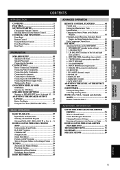
... THE LEVEL OF THE EFFECT SPEAKERS 66 SLEEP TIMER 67 Setting the Sleep Timer 67 Canceling the Sleep Timer 67 ZONE 2 (For U.S.A., Canada and Australia models 68 Remote Control in the Display Window 48 Clearing Learned Functions, Renamed Source Names, and Setup Manufacturer Codes 49 Each Component Control Area 50 SET...
... THE LEVEL OF THE EFFECT SPEAKERS 66 SLEEP TIMER 67 Setting the Sleep Timer 67 Canceling the Sleep Timer 67 ZONE 2 (For U.S.A., Canada and Australia models 68 Remote Control in the Display Window 48 Clearing Learned Functions, Renamed Source Names, and Setup Manufacturer Codes 49 Each Component Control Area 50 SET...

Owner's Manual
Page 6
...Decoder N Dolby Digital/Dolby Digital EX Decoder N DTS/DTS ES Matrix 6.1, Discrete 6.1, DTS Neo: 6 Decoder N CINEMA DSP: Combination of YAMAHA DSP Technology and Dolby Pro Logic, Dolby Digital or DTS N Virtual CINEMA DSP N SILENT CINEMA DSP Sophisticated AM/FM Tuner N 40-Station Random... Preset Manufacturer Codes and "Learning" Capability N PROCESSOR DIRECT for no alteration of the original signal N Custom Installation Facility (U.S.A., Canada and Australia models only) • y indicates a tip for the purpose of the improvement in this case the product has priority. In this manual. &#...
...Decoder N Dolby Digital/Dolby Digital EX Decoder N DTS/DTS ES Matrix 6.1, Discrete 6.1, DTS Neo: 6 Decoder N CINEMA DSP: Combination of YAMAHA DSP Technology and Dolby Pro Logic, Dolby Digital or DTS N Virtual CINEMA DSP N SILENT CINEMA DSP Sophisticated AM/FM Tuner N 40-Station Random... Preset Manufacturer Codes and "Learning" Capability N PROCESSOR DIRECT for no alteration of the original signal N Custom Installation Facility (U.S.A., Canada and Australia models only) • y indicates a tip for the purpose of the improvement in this case the product has priority. In this manual. &#...
Owner's Manual
Page 7
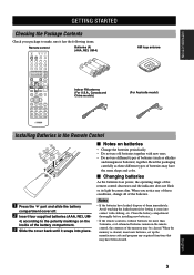
... 7 MOVIE THEATER 1 8 MOVIE THEATER 2 9 /DTS SUR. 10 0 SELECT 11 +10 EX/ES 12 CHP/INDEX Indoor FM antenna (For U.S.A., Canada and China models) AM loop antenna (For Australia model) Installing Batteries in the remote control, the contents of batteries (such as these conditions, change all of the batteries. Read the packaging carefully...
... 7 MOVIE THEATER 1 8 MOVIE THEATER 2 9 /DTS SUR. 10 0 SELECT 11 +10 EX/ES 12 CHP/INDEX Indoor FM antenna (For U.S.A., Canada and China models) AM loop antenna (For Australia model) Installing Batteries in the remote control, the contents of batteries (such as these conditions, change all of the batteries. Read the packaging carefully...
Owner's Manual
Page 13
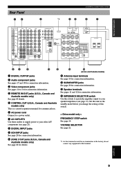
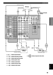
... 18 for connection information. 3 Video component jacks See pages 14 to your speaker impedance (see page 21). 8 DIGITAL INPUT jacks < China model only > FREQUENCY STEP switch See page 19. e Speaker terminals See pages 11 and 12 for commercial use. ADVANCED OPERATION ADDITIONAL INFORMATION APPENDIX English... information. VOLTAGE SELECTOR See page 21. 9 6CH INPUT jacks See page 20 for connection information. 0 ZONE 2 OUT jacks (U.S.A., Canada and Australia models only) See page 68 for details. *1 As this switch. 6 AC power cord Connect to a power outlet. 7 AC OUTLETS Use these outlets...
... 18 for connection information. 3 Video component jacks See pages 14 to your speaker impedance (see page 21). 8 DIGITAL INPUT jacks < China model only > FREQUENCY STEP switch See page 19. e Speaker terminals See pages 11 and 12 for commercial use. ADVANCED OPERATION ADDITIONAL INFORMATION APPENDIX English... information. VOLTAGE SELECTOR See page 21. 9 6CH INPUT jacks See page 20 for connection information. 0 ZONE 2 OUT jacks (U.S.A., Canada and Australia models only) See page 68 for details. *1 As this switch. 6 AC power cord Connect to a power outlet. 7 AC OUTLETS Use these outlets...
Owner's Manual
Page 14
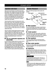
... equivalent performance with the same tonal quality. Turn it . We recommend that you place the speakers. The other terminals you use the models of the subwoofer is ideal for the center sounds (dialog, vocals, etc.). I Rear speakers Place these speakers behind your present stereo ...used for reproducing the LFE (low-frequency effect) channel with the full system. Best results, however, are not highly directional. The YAMAHA Active Servo Processing Subwoofer System is not so critical, because low bass sounds are obtained with high fidelity when the Dolby Digital signal ...
... equivalent performance with the same tonal quality. Turn it . We recommend that you place the speakers. The other terminals you use the models of the subwoofer is ideal for the center sounds (dialog, vocals, etc.). I Rear speakers Place these speakers behind your present stereo ...used for reproducing the LFE (low-frequency effect) channel with the full system. Best results, however, are not highly directional. The YAMAHA Active Servo Processing Subwoofer System is not so critical, because low bass sounds are obtained with high fidelity when the Dolby Digital signal ...
Owner's Manual
Page 15
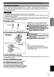
... bare speaker wires touch each of the speaker cables. 2 Twist the exposed wires of the MAIN A or B terminals. Banana plug y (For U.S.A., Canada, Australia and China models) • Banana plug connections are faulty, no sound will be connected to connect the left channel (L), right channel (R), "+" (red) and "-" (black) properly. INTRODUCTION PREPARATION BASIC...
... bare speaker wires touch each of the speaker cables. 2 Twist the exposed wires of the MAIN A or B terminals. Banana plug y (For U.S.A., Canada, Australia and China models) • Banana plug connections are faulty, no sound will be connected to connect the left channel (L), right channel (R), "+" (red) and "-" (black) properly. INTRODUCTION PREPARATION BASIC...
Owner's Manual
Page 16
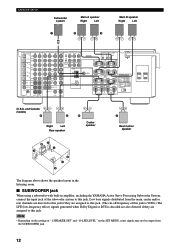
B - and Canada models) 4 5 Right Left Rear speaker 6 Center speaker 7 Rear Center speaker 62 1 3 4 7 5 The diagram above shows the speaker layout in amplifier, including the YAMAHA Active Servo Processing Subwoofer System, connect the input jack of the subwoofer system to this jack. (The cut-off frequency of "1 SPEAKER SET" and "10 ...
B - and Canada models) 4 5 Right Left Rear speaker 6 Center speaker 7 Rear Center speaker 62 1 3 4 7 5 The diagram above shows the speaker layout in amplifier, including the YAMAHA Active Servo Processing Subwoofer System, connect the input jack of the subwoofer system to this jack. (The cut-off frequency of "1 SPEAKER SET" and "10 ...

Owner's Manual
Page 17
.... Left Center The impedance must be 8 Ω or higher. Rear The impedance must be 8 Ω or higher. and Canada models] The impedance of the speakers in the standby mode. and Canada models) Rear The impedance of each speaker must be 6 Ω or higher. BASIC OPERATION ADVANCED OPERATION ADDITIONAL INFORMATION APPENDIX English 13...
.... Left Center The impedance must be 8 Ω or higher. Rear The impedance must be 8 Ω or higher. and Canada models] The impedance of the speakers in the standby mode. and Canada models) Rear The impedance of each speaker must be 6 Ω or higher. BASIC OPERATION ADVANCED OPERATION ADDITIONAL INFORMATION APPENDIX English 13...
Owner's Manual
Page 19
... S-video cables APPENDIX English 15 OUTPUT + - INTRODUCTION PREPARATION OPTICAL OUTPUT AUDIO OUTPUT DVD player CONNECTIONS COMPONENT OUTPUT VIDEO S VIDEO OUTPUT OUTPUT O LR V S VV V (U.S.A. and Canada models) DIGITAL OUTPUT OPTICAL MD/TAPE IN (PLAY) AUDIO R L CD-R MD/TAPE OUT (REC) CD CD-R IN (PLAY) CD-R OUT (REC) DVD CBL /SAT CD PHONO...
... S-video cables APPENDIX English 15 OUTPUT + - INTRODUCTION PREPARATION OPTICAL OUTPUT AUDIO OUTPUT DVD player CONNECTIONS COMPONENT OUTPUT VIDEO S VIDEO OUTPUT OUTPUT O LR V S VV V (U.S.A. and Canada models) DIGITAL OUTPUT OPTICAL MD/TAPE IN (PLAY) AUDIO R L CD-R MD/TAPE OUT (REC) CD CD-R IN (PLAY) CD-R OUT (REC) DVD CBL /SAT CD PHONO...
Owner's Manual
Page 20
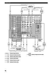
and Canada models) LR LR V V S S VIDEO OUTPUT VIDEO INPUT AUDIO INPUT AUDIO OUTPUT VCR 1 or VCR 2/ DVR (digital video recorder) S VIDEO OUTPUT S VIDEO INPUT indicates signal direction L indicates ...
and Canada models) LR LR V V S S VIDEO OUTPUT VIDEO INPUT AUDIO INPUT AUDIO OUTPUT VCR 1 or VCR 2/ DVR (digital video recorder) S VIDEO OUTPUT S VIDEO INPUT indicates signal direction L indicates ...

Owner's Manual
Page 22
and Canada models) OPTICAL INPUT OUTPUT CD recorder INPUT O LR O L R OPTICAL OUTPUT GND OUTPUT LR Turntable indicates signal direction L indicates left audio pin cables R indicates right audio pin ...
and Canada models) OPTICAL INPUT OUTPUT CD recorder INPUT O LR O L R OPTICAL OUTPUT GND OUTPUT LR Turntable indicates signal direction L indicates left audio pin cables R indicates right audio pin ...
Owner's Manual
Page 23
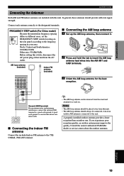
...the 75Ω UNBAL. Notes • The AM loop antenna should be placed away from the AC outlet. Consult the nearest authorized YAMAHA dealer or service center about the outdoor antennas. Ground (GND terminal) For maximum safety and minimum interference, connect the antenna GND terminal to...these antennas should always be removed from the stand and attached to the frequency spacing in your area. FREQUENCY STEP switch (For China model) Because the interstation frequency spacing 100kHz/10kHz differs in different areas, set the FREQUENCY STEP switch (locating on 50kHz/9kHz FM AM FREQUENCY...
...the 75Ω UNBAL. Notes • The AM loop antenna should be placed away from the AC outlet. Consult the nearest authorized YAMAHA dealer or service center about the outdoor antennas. Ground (GND terminal) For maximum safety and minimum interference, connect the antenna GND terminal to...these antennas should always be removed from the stand and attached to the frequency spacing in your area. FREQUENCY STEP switch (For China model) Because the interstation frequency spacing 100kHz/10kHz differs in different areas, set the FREQUENCY STEP switch (locating on 50kHz/9kHz FM AM FREQUENCY...

Owner's Manual
Page 25
...to the AC OUTLET(S) is turned on the rear panel of components) that can be connected to the wall outlet. and Canada models 80 W China model 50 W Australia model 100 W VOLTAGE SELECTOR VOLTAGE SELECTOR PEDANCE SELECTOR T BEFORE POWER ON N A OR B: 4ΩMIN. /SPEAKER A+B: 8ΩMIN...ΩMIN. /SPEAKER CENTER : 8ΩMIN. /SPEAKER REAR CENTER: 8ΩMIN. /SPEAKER REAR : 8ΩMIN. /SPEAKER AC OUTLETS I VOLTAGE SELECTOR (China model only) The VOLTAGE SELECTOR on . EDANCE SELECTOR T BEFORE POWER ON A OR B: 4ΩMIN. /SPEAKER A+B: 8ΩMIN. /SPEAKER ER : 6ΩMIN. ...
...to the AC OUTLET(S) is turned on the rear panel of components) that can be connected to the wall outlet. and Canada models 80 W China model 50 W Australia model 100 W VOLTAGE SELECTOR VOLTAGE SELECTOR PEDANCE SELECTOR T BEFORE POWER ON N A OR B: 4ΩMIN. /SPEAKER A+B: 8ΩMIN...ΩMIN. /SPEAKER CENTER : 8ΩMIN. /SPEAKER REAR CENTER: 8ΩMIN. /SPEAKER REAR : 8ΩMIN. /SPEAKER AC OUTLETS I VOLTAGE SELECTOR (China model only) The VOLTAGE SELECTOR on . EDANCE SELECTOR T BEFORE POWER ON A OR B: 4ΩMIN. /SPEAKER A+B: 8ΩMIN. /SPEAKER ER : 6ΩMIN. ...
Owner's Manual
Page 49
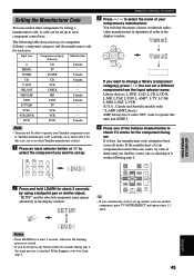
...initially set up in each component control area. MD/TAPE MD Yamaha CD-R CD-R Yamaha D-TV/LD TV - Library choices: L:DVD, L:LD, L:CD, L:CD-R, L:MD, L:TAP, L:TUN, L:AMP*, L:TV, L:CAB, L:DBS, L:SAT, L:VCR (U.S.A., Canada and Australia models only) *L:AMP (AMP Library) AMP Library has 2 codes: ...set as checking if it works following table shows factory-set a different component from step 2. 45 The following step 4. TUNER TUNER Yamaha CD CD Yamaha V-AUX VCR - CBL/SAT CABLE - CH + PRESET If you do not press any button within 30 seconds during step 3,...
...initially set up in each component control area. MD/TAPE MD Yamaha CD-R CD-R Yamaha D-TV/LD TV - Library choices: L:DVD, L:LD, L:CD, L:CD-R, L:MD, L:TAP, L:TUN, L:AMP*, L:TV, L:CAB, L:DBS, L:SAT, L:VCR (U.S.A., Canada and Australia models only) *L:AMP (AMP Library) AMP Library has 2 codes: ...set as checking if it works following table shows factory-set a different component from step 2. 45 The following step 4. TUNER TUNER Yamaha CD CD Yamaha V-AUX VCR - CBL/SAT CABLE - CH + PRESET If you do not press any button within 30 seconds during step 3,...
Owner's Manual
Page 72
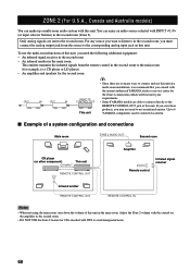
...or service center for the Zone 2 connections which will best meet your REMOTE requirements. OUT IN OUT IN CONTROL OUT • Some YAMAHA models are able to connect directly to avoid unexpected noise. 68 If you own these products, you may not need the following additional equipment: ... the second room. • DO NOT USE the Zone 2 feature for the second room y • Since there are sent to 6 This unit YAMAHA components can enjoy an audio source selected with this unit. Up to the second room. I Example of a system configuration and connections Main room ZONE 2...
...or service center for the Zone 2 connections which will best meet your REMOTE requirements. OUT IN OUT IN CONTROL OUT • Some YAMAHA models are able to connect directly to avoid unexpected noise. 68 If you own these products, you may not need the following additional equipment: ... the second room. • DO NOT USE the Zone 2 feature for the second room y • Since there are sent to 6 This unit YAMAHA components can enjoy an audio source selected with this unit. Up to the second room. I Example of a system configuration and connections Main room ZONE 2...
Owner's Manual
Page 84
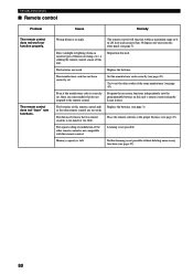
... weak. The batteries of the same maufacturer (see page 47). Wrong distance or angle. The manufacturer code has not been correctly set , there are some models that do not respond to set the other codes of this unit. The signal coding or modulation of the other remote control are weak. Reposition...
... weak. The batteries of the same maufacturer (see page 47). Wrong distance or angle. The manufacturer code has not been correctly set , there are some models that do not respond to set the other codes of this unit. The signal coding or modulation of the other remote control are weak. Reposition...


