
Owner's Manual
Page 2
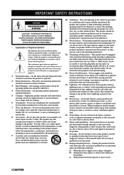
...been spilled, or objects have been adhered to persons. All operating and use instructions should be operated only from the type of overhead power lines or other sources, refer to the product. Do not use a mounting accessory recommended by the product manufacturer as contact with the ... tub; The product may cause hazards. 7 Water and Moisture - This plug will prevent damage to the product due to lightning and power-line surges. 15 Power Lines - An outside antenna system, extreme care should use this product on a bed, sofa, rug, or other hazards. When installing...
...been spilled, or objects have been adhered to persons. All operating and use instructions should be operated only from the type of overhead power lines or other sources, refer to the product. Do not use a mounting accessory recommended by the product manufacturer as contact with the ... tub; The product may cause hazards. 7 Water and Moisture - This plug will prevent damage to the product due to lightning and power-line surges. 15 Power Lines - An outside antenna system, extreme care should use this product on a bed, sofa, rug, or other hazards. When installing...
Owner's Manual
Page 3
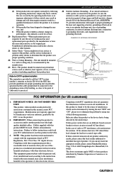
...the National Electrical Code, ANSI/NFPA 70, provides information with other electronic devices. Modifications not expressly approved by Yamaha may result in harmful interference with regard to grounding electrodes, and requirements for service. 20 Replacement Parts - ...Yamaha Corporation of radio or TV interference, relocate/reorient the antenna. EXAMPLE OF ANTENNA GROUNDING MAST GROUND CLAMP ELECTRIC SERVICE EQUIPMENT NEC - NATIONAL ELECTRICAL CODE ANTENNA LEAD IN WIRE ANTENNA DISCHARGE UNIT (NEC SECTION 810-20) GROUNDING CONDUCTORS (NEC SECTION 810-21) GROUND CLAMPS POWER...
...the National Electrical Code, ANSI/NFPA 70, provides information with other electronic devices. Modifications not expressly approved by Yamaha may result in harmful interference with regard to grounding electrodes, and requirements for service. 20 Replacement Parts - ...Yamaha Corporation of radio or TV interference, relocate/reorient the antenna. EXAMPLE OF ANTENNA GROUNDING MAST GROUND CLAMP ELECTRIC SERVICE EQUIPMENT NEC - NATIONAL ELECTRICAL CODE ANTENNA LEAD IN WIRE ANTENNA DISCHARGE UNIT (NEC SECTION 810-20) GROUNDING CONDUCTORS (NEC SECTION 810-21) GROUND CLAMPS POWER...
Owner's Manual
Page 4
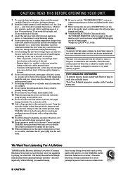
... components, as they may overheat, possibly causing damage. 9 Do not use this unit for future reference. 2 Install this manual carefully. YAMAHA will not be held responsible for any damage resulting from use of your local main voltage BEFORE plugging into the AC main supply. WARNING... place for long periods of plug to the wall outlet, even if this unit. vacation), disconnect the AC power plug from loud sounds is too late, YAMAHA and the Electronic Industries Association's Consumer Electronics Group recommend you to get the most importantly, without annoying blaring or...
... components, as they may overheat, possibly causing damage. 9 Do not use this unit for future reference. 2 Install this manual carefully. YAMAHA will not be held responsible for any damage resulting from use of your local main voltage BEFORE plugging into the AC main supply. WARNING... place for long periods of plug to the wall outlet, even if this unit. vacation), disconnect the AC power plug from loud sounds is too late, YAMAHA and the Electronic Industries Association's Consumer Electronics Group recommend you to get the most importantly, without annoying blaring or...
Owner's Manual
Page 5
... 14 Connecting Audio Components 17 Connecting the Antennas 19 Connecting to a Subwoofer 20 Connecting to the 6CH INPUT Jacks 20 Connecting the Power Supply Cords 21 Turning on the Power 22 ON-SCREEN DISPLAY (OSD 23 OSD Modes 23 Selecting the OSD Mode 23 SPEAKER MODE SETTINGS 24 Summary of SPEAKER SET...
... 14 Connecting Audio Components 17 Connecting the Antennas 19 Connecting to a Subwoofer 20 Connecting to the 6CH INPUT Jacks 20 Connecting the Power Supply Cords 21 Turning on the Power 22 ON-SCREEN DISPLAY (OSD 23 OSD Modes 23 Selecting the OSD Mode 23 SPEAKER MODE SETTINGS 24 Summary of SPEAKER SET...

Owner's Manual
Page 6
...the product has priority. Design and specifications are trademarks of Digital Theater System, Inc. 2 FEATURES Built-in 6-Channel Power Amplifier N Minimum RMS Output Power (0.04% THD, 20 Hz - 20 kHz, 8Ω) Main: 100 W + 100 W Center: 100 ...W Rear: 100 W + 100 W Rear center: 100 W Multi-Mode Digital Sound Field Processing N Dolby Pro Logic/Dolby Pro Logic Decoder N Dolby Digital/Dolby Digital EX Decoder N DTS/DTS ES Matrix 6.1, Discrete 6.1, DTS Neo: 6 Decoder N CINEMA DSP: Combination of YAMAHA...
...the product has priority. Design and specifications are trademarks of Digital Theater System, Inc. 2 FEATURES Built-in 6-Channel Power Amplifier N Minimum RMS Output Power (0.04% THD, 20 Hz - 20 kHz, 8Ω) Main: 100 W + 100 W Center: 100 ...W Rear: 100 W + 100 W Rear center: 100 W Multi-Mode Digital Sound Field Processing N Dolby Pro Logic/Dolby Pro Logic Decoder N Dolby Digital/Dolby Digital EX Decoder N DTS/DTS ES Matrix 6.1, Discrete 6.1, DTS Neo: 6 Decoder N CINEMA DSP: Combination of YAMAHA...
Owner's Manual
Page 7
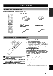
... Batteries (4) (AAA, R03, UM-4) A PHONO TUNER CD V-AUX CBL/SAT MD/TAPE CD-R D-TV/LD VCR 1 VCR2/DVR DVD SELECT POWER TV REC DISC SKIP POWER AV AMP AUDIO + VOL - ADVANCED OPERATION ADDITIONAL INFORMATION APPENDIX English 3 TV MUTE SELECT CH + PRESET TEST RETURN HALL 1 TV VOL - CHURCH... in the remote control, the contents of the memory may have leaked, dispose of them immediately. I Changing batteries As the batteries lose power, the operating range of the remote control decreases and the indicator does not flash or its light becomes dim. Notes • If the...
... Batteries (4) (AAA, R03, UM-4) A PHONO TUNER CD V-AUX CBL/SAT MD/TAPE CD-R D-TV/LD VCR 1 VCR2/DVR DVD SELECT POWER TV REC DISC SKIP POWER AV AMP AUDIO + VOL - ADVANCED OPERATION ADDITIONAL INFORMATION APPENDIX English 3 TV MUTE SELECT CH + PRESET TEST RETURN HALL 1 TV VOL - CHURCH... in the remote control, the contents of the memory may have leaked, dispose of them immediately. I Changing batteries As the batteries lose power, the operating range of the remote control decreases and the indicator does not flash or its light becomes dim. Notes • If the...
Owner's Manual
Page 8
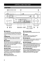
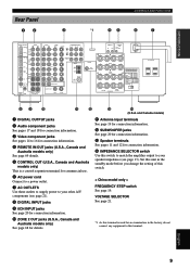
... sensor Receives signals from the remote control. 6 Front panel display Shows information about the operational status of this unit. 7 VOLUME Controls the output level of power to receive infrared-signals from the remote control. 2 6CH (INPUT) Selects the source connected to two or more input jacks of the original signal. 4
... sensor Receives signals from the remote control. 6 Front panel display Shows information about the operational status of this unit. 7 VOLUME Controls the output level of power to receive infrared-signals from the remote control. 2 6CH (INPUT) Selects the source connected to two or more input jacks of the original signal. 4
Owner's Manual
Page 10
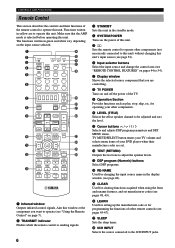
...remote controls (see pages 48, 49). t CLEAR Used for changing the input source name in green and white vary depending on and off the power of the remote control to operate this unit. y LEARN Used for setting up the manufacturer code or for operating your DVD player when their .... Make sure that the AMP mode is sending signals. 3 STANDBY Sets this unit in yellow are controlling. 8 TV POWER Turns on the input source selected. 1 2 3 4 5 6 TRANSMIT RE-NAME CLEAR LEARN SYSTEM POWER STANDBY SLEEP 6CH INPUT A PHONO TUNER CD V-AUX CBL/SAT MD/TAPE CD-R D-TV/LD VCR 1 VCR2/DVR ...
...remote controls (see pages 48, 49). t CLEAR Used for changing the input source name in green and white vary depending on and off the power of the remote control to operate this unit. y LEARN Used for setting up the manufacturer code or for operating your DVD player when their .... Make sure that the AMP mode is sending signals. 3 STANDBY Sets this unit in yellow are controlling. 8 TV POWER Turns on the input source selected. 1 2 3 4 5 6 TRANSMIT RE-NAME CLEAR LEARN SYSTEM POWER STANDBY SLEEP 6CH INPUT A PHONO TUNER CD V-AUX CBL/SAT MD/TAPE CD-R D-TV/LD VCR 1 VCR2/DVR ...
Owner's Manual
Page 11
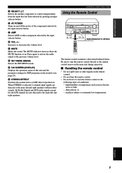
... or other component selected by the input selector button. high humidity or temperature such as near a heater, stove or bath; - or - p AV POWER Turns on and off the power of this unit and the parameter settings for the LFE channel are directed to aim the remote control directly at the remote control...
... or other component selected by the input selector button. high humidity or temperature such as near a heater, stove or bath; - or - p AV POWER Turns on and off the power of this unit and the parameter settings for the LFE channel are directed to aim the remote control directly at the remote control...
Owner's Manual
Page 13
...OPERATION ADDITIONAL INFORMATION APPENDIX English 9 r IMPEDANCE SELECTOR switch Use this switch. 6 AC power cord Connect to a power outlet. 7 AC OUTLETS Use these outlets to supply power to 16 for connection information. 4 REMOTE IN/OUT jacks (U.S.A., Canada and Australia models...R+ REMOTE IN OUT CONTROL OUT +12V 15mA MAX. -A - +L OUTPUT SUB WOOFER + R+ + - REAR (SURROUND) - - - + +L + IMPEDANCE SELECTOR SET BEFORE POWER ON MAIN A OR B: 4ΩMIN. /SPEAKER A+B: 8ΩMIN. /SPEAKER CENTER : 6ΩMIN. /SPEAKER REAR CENTER: 6ΩMIN. /SPEAKER REAR : 6ΩMIN...
...OPERATION ADDITIONAL INFORMATION APPENDIX English 9 r IMPEDANCE SELECTOR switch Use this switch. 6 AC power cord Connect to a power outlet. 7 AC OUTLETS Use these outlets to supply power to 16 for connection information. 4 REMOTE IN/OUT jacks (U.S.A., Canada and Australia models...R+ REMOTE IN OUT CONTROL OUT +12V 15mA MAX. -A - +L OUTPUT SUB WOOFER + R+ + - REAR (SURROUND) - - - + +L + IMPEDANCE SELECTOR SET BEFORE POWER ON MAIN A OR B: 4ΩMIN. /SPEAKER A+B: 8ΩMIN. /SPEAKER CENTER : 6ΩMIN. /SPEAKER REAR CENTER: 6ΩMIN. /SPEAKER REAR : 6ΩMIN...
Owner's Manual
Page 14
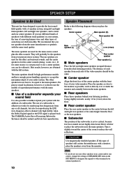
... manufacturer or speakers with the front face of a subwoofer. The other speakers do not have to be high-performance models and have enough power-handling capacity to accept the maximum output of the center speaker with the same tonal quality. I Rear center speaker Place the rear center...main speakers, left and right main speakers an equal distance from the ideal listening position. The rear speakers are not highly directional. The YAMAHA Active Servo Processing Subwoofer System is not so critical, because low bass sounds are used for some reason it is not practical to ...
... manufacturer or speakers with the front face of a subwoofer. The other speakers do not have to be high-performance models and have enough power-handling capacity to accept the maximum output of the center speaker with the same tonal quality. I Rear center speaker Place the rear center...main speakers, left and right main speakers an equal distance from the ideal listening position. The rear speakers are not highly directional. The YAMAHA Active Servo Processing Subwoofer System is not so critical, because low bass sounds are used for some reason it is not practical to ...
Owner's Manual
Page 16
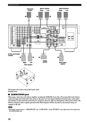
... Rear speaker 6 Center speaker 7 Rear Center speaker 62 1 3 4 7 5 The diagram above shows the speaker layout in amplifier, including the YAMAHA Active Servo Processing Subwoofer System, connect the input jack of "1 SPEAKER SET" and "10 LFE LEVEL" on the settings of the subwoofer system to...OUT IN VCR 1 OUT IN VCR 2 /DVR OUT TUNER AM ANT GND FM ANT 75Ω UNBAL. REAR (SURROUND) - - - + +L + IMPEDANCE SELECTOR SET BEFORE POWER ON MAIN A OR B: 4ΩMIN. /SPEAKER A+B: 8ΩMIN. /SPEAKER CENTER : 6ΩMIN. /SPEAKER REAR CENTER: 6ΩMIN. /SPEAKER REAR : 6ΩMIN....
... Rear speaker 6 Center speaker 7 Rear Center speaker 62 1 3 4 7 5 The diagram above shows the speaker layout in amplifier, including the YAMAHA Active Servo Processing Subwoofer System, connect the input jack of "1 SPEAKER SET" and "10 LFE LEVEL" on the settings of the subwoofer system to...OUT IN VCR 1 OUT IN VCR 2 /DVR OUT TUNER AM ANT GND FM ANT 75Ω UNBAL. REAR (SURROUND) - - - + +L + IMPEDANCE SELECTOR SET BEFORE POWER ON MAIN A OR B: 4ΩMIN. /SPEAKER A+B: 8ΩMIN. /SPEAKER CENTER : 6ΩMIN. /SPEAKER REAR CENTER: 6ΩMIN. /SPEAKER REAR : 6ΩMIN....

Owner's Manual
Page 17
.... [U.S.A. If you use two sets of main speakers, the impedance of each speaker must be 8 Ω or higher. IMPEDANCE SELECTOR switch IMPEDANCE SELECTOR SET BEFORE POWER ON MAIN A OR B: 4ΩMIN. /SPEAKER A+B: 8ΩMIN. /SPEAKER CENTER : 6ΩMIN. /SPEAKER REAR CENTER: 6ΩMIN. /SPEAKER REAR : 6ΩMIN. /SPEAKER MAIN... English 13 INTRODUCTION PREPARATION I IMPEDANCE SELECTOR switch SPEAKER SETUP WARNING Do not change the IMPEDANCE SELECTOR switch setting while the power of this unit is in the standby mode. If this unit fails to turn on when STANDBY/ON (or SYSTEM...
.... [U.S.A. If you use two sets of main speakers, the impedance of each speaker must be 8 Ω or higher. IMPEDANCE SELECTOR switch IMPEDANCE SELECTOR SET BEFORE POWER ON MAIN A OR B: 4ΩMIN. /SPEAKER A+B: 8ΩMIN. /SPEAKER CENTER : 6ΩMIN. /SPEAKER REAR CENTER: 6ΩMIN. /SPEAKER REAR : 6ΩMIN. /SPEAKER MAIN... English 13 INTRODUCTION PREPARATION I IMPEDANCE SELECTOR switch SPEAKER SETUP WARNING Do not change the IMPEDANCE SELECTOR switch setting while the power of this unit is in the standby mode. If this unit fails to turn on when STANDBY/ON (or SYSTEM...
Owner's Manual
Page 18
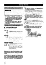
... jack on the SET MENU (see pages 61 and 62 for the COMPONENT VIDEO A and B jacks according to your monitor and other components to mains power until all connections are separated into luminance (Y) and color difference (PB / CB, PR/CR) to achieve high-quality color reproduction. CONNECTIONS Before Connecting Components CAUTION...
... jack on the SET MENU (see pages 61 and 62 for the COMPONENT VIDEO A and B jacks according to your monitor and other components to mains power until all connections are separated into luminance (Y) and color difference (PB / CB, PR/CR) to achieve high-quality color reproduction. CONNECTIONS Before Connecting Components CAUTION...
Owner's Manual
Page 21
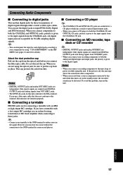
...-head amplifier when connecting to reduce noise in the signal. If you have a turntable with an MM or high-output MC cartridge. If the power is set in place. y • Connect your component by using the optical jack, be distorted. You can designate the input for each digital...GND terminal for a CD player which has coaxial or optical digital output jacks. • When you connect a recording component to this unit, keep its power on this unit. All digital input jacks are not using "7 I Connecting a CD player y • The COAXIAL CD and OPTICAL CD jacks are output...
...-head amplifier when connecting to reduce noise in the signal. If you have a turntable with an MM or high-output MC cartridge. If the power is set in place. y • Connect your component by using the optical jack, be distorted. You can designate the input for each digital...GND terminal for a CD player which has coaxial or optical digital output jacks. • When you connect a recording component to this unit, keep its power on this unit. All digital input jacks are not using "7 I Connecting a CD player y • The COAXIAL CD and OPTICAL CD jacks are output...
Owner's Manual
Page 23
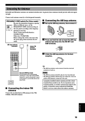
...indoor FM antenna to the 75Ω UNBAL. FM ANT terminal. 3 Orient the AM loop antenna for the beat reception. Consult the nearest authorized YAMAHA dealer or service center about the outdoor antennas. North, Central and South America: 100 kHz/10 kHz Other area: 50 kHz/9 kHz Before setting ...this switch, disconnect the AC power plug of this unit from this unit. • The AM loop antenna should always be connected, even if an outdoor AM antenna is a metal...
...indoor FM antenna to the 75Ω UNBAL. FM ANT terminal. 3 Orient the AM loop antenna for the beat reception. Consult the nearest authorized YAMAHA dealer or service center about the outdoor antennas. North, Central and South America: 100 kHz/10 kHz Other area: 50 kHz/9 kHz Before setting ...this switch, disconnect the AC power plug of this unit from this unit. • The AM loop antenna should always be connected, even if an outdoor AM antenna is a metal...

Owner's Manual
Page 25
... main voltage BEFORE plugging into the wall outlet. and Canada models 80 W China model 50 W Australia model 100 W VOLTAGE SELECTOR VOLTAGE SELECTOR PEDANCE SELECTOR T BEFORE POWER ON N A OR B: 4ΩMIN. /SPEAKER A+B: 8ΩMIN. /SPEAKER TER : 6ΩMIN. /SPEAKER R CENTER: 6ΩMIN. /SPEAKER R : 6ΩMIN. /SPEAKER ...rear panel of components) that can be set for your components to this unit's STANDBY/ON (or SYSTEM POWER and STANDBY). The maximum power (total power consumption of this unit must be connected to the wall outlet. and Canada models) To AC outlet Plug ...
... main voltage BEFORE plugging into the wall outlet. and Canada models 80 W China model 50 W Australia model 100 W VOLTAGE SELECTOR VOLTAGE SELECTOR PEDANCE SELECTOR T BEFORE POWER ON N A OR B: 4ΩMIN. /SPEAKER A+B: 8ΩMIN. /SPEAKER TER : 6ΩMIN. /SPEAKER R CENTER: 6ΩMIN. /SPEAKER R : 6ΩMIN. /SPEAKER ...rear panel of components) that can be set for your components to this unit's STANDBY/ON (or SYSTEM POWER and STANDBY). The maximum power (total power consumption of this unit must be connected to the wall outlet. and Canada models) To AC outlet Plug ...
Owner's Manual
Page 26
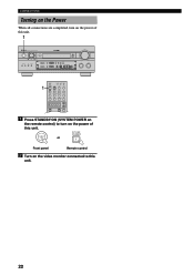
... MODE EDIT PHONES MAN'L/AUTO FM AUTO/MAN'L MONO S VIDEO VIDEO L AUDIO R OPTICAL SILENT VIDEO AUX VOLUME BASS TREBLE - + - + 1 TRANSMIT RE-NAME CLEAR LEARN SYSTEM POWER STANDBY SLEEP 6CH INPUT A PHONO TUNER CD V-AUX CBL/SAT MD/TAPE CD-R D-TV/LD VCR 1 VCR2/DVR DVD... POWER TV REC SELECT POWER AV AMP 1 Press STANDBY/ON (SYSTEM POWER on the remote control) to turn on the video monitor connected to this unit. CONNECTIONS Turning on the Power When all connections are completed, turn on the...
... MODE EDIT PHONES MAN'L/AUTO FM AUTO/MAN'L MONO S VIDEO VIDEO L AUDIO R OPTICAL SILENT VIDEO AUX VOLUME BASS TREBLE - + - + 1 TRANSMIT RE-NAME CLEAR LEARN SYSTEM POWER STANDBY SLEEP 6CH INPUT A PHONO TUNER CD V-AUX CBL/SAT MD/TAPE CD-R D-TV/LD VCR 1 VCR2/DVR DVD... POWER TV REC SELECT POWER AV AMP 1 Press STANDBY/ON (SYSTEM POWER on the remote control) to turn on the video monitor connected to this unit. CONNECTIONS Turning on the Power When all connections are completed, turn on the...
Owner's Manual
Page 27
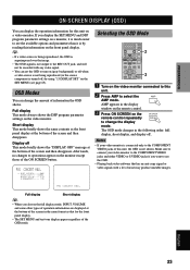
... than it is not shown. P01 CONCERT HALL ≥ DSP LEVEL............0dB INIT.DLY............45ms ROOM SIZE............1.O LIVENESS 5 Selecting the OSD Mode SELECT POWER TV REC DISC SKIP POWER AV AMP AUDIO + VOL - AMP appears in the display window on the remote control. 3 Press ON SCREEN on the front panel display. P01...
... than it is not shown. P01 CONCERT HALL ≥ DSP LEVEL............0dB INIT.DLY............45ms ROOM SIZE............1.O LIVENESS 5 Selecting the OSD Mode SELECT POWER TV REC DISC SKIP POWER AV AMP AUDIO + VOL - AMP appears in the display window on the remote control. 3 Press ON SCREEN on the front panel display. P01...
Owner's Manual
Page 29
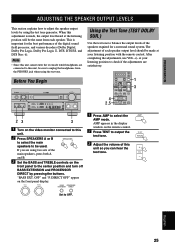
... AUX VOLUME BASS TREBLE - + - + Using the Test Tone (TEST DOLBY SUR.) Use the test tone to check if the adjustments are satisfactory. 4 2,5 SELECT POWER TV REC DISC SKIP POWER AV AMP AUDIO + VOL - at the listening position will be the same from the PHONES jack when using the test tone generator. PRESET...
... AUX VOLUME BASS TREBLE - + - + Using the Test Tone (TEST DOLBY SUR.) Use the test tone to check if the adjustments are satisfactory. 4 2,5 SELECT POWER TV REC DISC SKIP POWER AV AMP AUDIO + VOL - at the listening position will be the same from the PHONES jack when using the test tone generator. PRESET...


