
Owner's Manual
Page 3
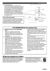
... your use only high quality shielded cables. NATIONAL ELECTRICAL CODE ANTENNA LEAD IN WIRE ANTENNA DISCHARGE UNIT (NEC SECTION 810-20) GROUNDING CONDUCTORS (NEC SECTION 810-21) GROUND CLAMPS POWER SERVICE GROUNDING ELECTRODE SYSTEM (NEC ART 250. and, most out of radio or TV interference, relocate/reorient the antenna. INTRODUCTION PREPARATION BASIC OPERATION ADVANCED OPERATION 19 For US customers only: Outdoor Antenna Grounding - PART...
... your use only high quality shielded cables. NATIONAL ELECTRICAL CODE ANTENNA LEAD IN WIRE ANTENNA DISCHARGE UNIT (NEC SECTION 810-20) GROUNDING CONDUCTORS (NEC SECTION 810-21) GROUND CLAMPS POWER SERVICE GROUNDING ELECTRODE SYSTEM (NEC ART 250. and, most out of radio or TV interference, relocate/reorient the antenna. INTRODUCTION PREPARATION BASIC OPERATION ADVANCED OPERATION 19 For US customers only: Outdoor Antenna Grounding - PART...
Owner's Manual
Page 5
...Sound Effect (turning off the effect speakers 25 TUNING 26 Connecting the Antennas 26 Automatic Tuning 27 Manual Tuning 27 Automatic Preset Tuning (for FM stations only 28 Manual Preset Tuning 29 To Recall a Preset Station 29 Exchanging Preset Stations 30 RECORDING A SOURCE 31 ADVANCED OPERATION SET MENU 32 Adjusting the Items on the SET MENU 32 1 SPEAKER SET (speaker mode settings 33 2 HP TONE CTRL (headphone tone control) ...... 34 3 I/O ASSIGN 34 4 INPUT MODE (initial input mode 35 5 DOLBY D. SET (Dolby Digital set 35 6 DTS SET (DTS LFE level 36 7 SP DLY TIME (center delay...
...Sound Effect (turning off the effect speakers 25 TUNING 26 Connecting the Antennas 26 Automatic Tuning 27 Manual Tuning 27 Automatic Preset Tuning (for FM stations only 28 Manual Preset Tuning 29 To Recall a Preset Station 29 Exchanging Preset Stations 30 RECORDING A SOURCE 31 ADVANCED OPERATION SET MENU 32 Adjusting the Items on the SET MENU 32 1 SPEAKER SET (speaker mode settings 33 2 HP TONE CTRL (headphone tone control) ...... 34 3 I/O ASSIGN 34 4 INPUT MODE (initial input mode 35 5 DOLBY D. SET (Dolby Digital set 35 6 DTS SET (DTS LFE level 36 7 SP DLY TIME (center delay...
Owner's Manual
Page 6
... buttons on the main unit or on various functions unique to each model, see the descriptions given for Other Future Formats N Video Signal Input and Output Capability (Including S Video Connections HTR-5450 only ) N Optical and Coaxial Digital Signal Input Jacks N SLEEP Timer N Remote Control with Preset Manufacturer Codes • This document is given in parentheses in this manual. "DTS" and "DTS Digital Surround" are trademarks of YAMAHA DSP Technology and Dolby Digital, Dolby Pro Logic or DTS N Virtual CINEMA DSP N SILENT CINEMA Sophisticated FM/AM Tuner...
... buttons on the main unit or on various functions unique to each model, see the descriptions given for Other Future Formats N Video Signal Input and Output Capability (Including S Video Connections HTR-5450 only ) N Optical and Coaxial Digital Signal Input Jacks N SLEEP Timer N Remote Control with Preset Manufacturer Codes • This document is given in parentheses in this manual. "DTS" and "DTS Digital Surround" are trademarks of YAMAHA DSP Technology and Dolby Digital, Dolby Pro Logic or DTS N Virtual CINEMA DSP N SILENT CINEMA Sophisticated FM/AM Tuner...
Owner's Manual
Page 8
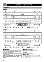
...MAN'L/AUTO FM AUTO/MAN'L MONO INPUT MODE INPUT 6CH INPUT 789 HTR-5440 1 SILENT 0 qw e 2 VIDEO AUX r t yu i op a 3 456 STANDBY /ON D I G I TA L SURROUND BASS TREBLE BALANCE -+ -+ L R SPEAKERS A B ON OFF D I G I TA L VOLUME PROGRAM PHONES EFFECT PRESET/TUNING VIDEO L AUDIO R A/B/C/D/E PRESET /TUNING FM/AM EDIT MEMORY TUNING MODE MAN'L/AUTO FM AUTO/MAN'L MONO INPUT MODE INPUT 6CH INPUT SILENT VIDEO AUX 7 8 9 0 qw e r t yu i op a 1 STANDBY/ON Press this switch to turn on , set this unit. 4 Before turning the power on the power of signals to set...
...MAN'L/AUTO FM AUTO/MAN'L MONO INPUT MODE INPUT 6CH INPUT 789 HTR-5440 1 SILENT 0 qw e 2 VIDEO AUX r t yu i op a 3 456 STANDBY /ON D I G I TA L SURROUND BASS TREBLE BALANCE -+ -+ L R SPEAKERS A B ON OFF D I G I TA L VOLUME PROGRAM PHONES EFFECT PRESET/TUNING VIDEO L AUDIO R A/B/C/D/E PRESET /TUNING FM/AM EDIT MEMORY TUNING MODE MAN'L/AUTO FM AUTO/MAN'L MONO INPUT MODE INPUT 6CH INPUT SILENT VIDEO AUX 7 8 9 0 qw e r t yu i op a 1 STANDBY/ON Press this switch to turn on , set this unit. 4 Before turning the power on the power of signals to set...
Owner's Manual
Page 9
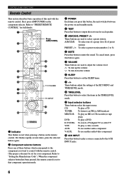
... display and switch the function between for storing a broadcasting station (preset tuning) and for private listening. When listening with INPUT l / h (or the input selector buttons on the display. This button is also used to exchange the assignment of the selected program appears on the remote control). 7 BASS Turn this control clockwise to increase or counterclockwise to decrease the low-frequency response. 8 TREBLE Turn this button to the ON position for the sound from the main speakers. e PHONES jack Connect...
... display and switch the function between for storing a broadcasting station (preset tuning) and for private listening. When listening with INPUT l / h (or the input selector buttons on the display. This button is also used to exchange the assignment of the selected program appears on the remote control). 7 BASS Turn this control clockwise to increase or counterclockwise to decrease the low-frequency response. 8 TREBLE Turn this button to the ON position for the sound from the main speakers. e PHONES jack Connect...
Owner's Manual
Page 10
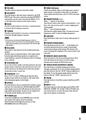
... tape deck) DVD: To play a DVD D-TV/CBL: To watch a TV/digital TV or cable TV VCR: To play a video cassette AUX: To use another audio component V-AUX: To use another audio/video component w 6CH INPUT Press this button, the unit switches between the power on the component selector. A/B/C/D/E: To select one of these buttons which corresponds to the component you press this button to play a source connected to output the test tone for full details. 1 Press AMP(TUNER). 2 3 q w 4 e 5 6 TV VOLUME 7 8 TV INPUT 9 r 0 t 1 Indicator This flashes in the TIME/LEVEL mode...
... tape deck) DVD: To play a DVD D-TV/CBL: To watch a TV/digital TV or cable TV VCR: To play a video cassette AUX: To use another audio component V-AUX: To use another audio/video component w 6CH INPUT Press this button, the unit switches between the power on the component selector. A/B/C/D/E: To select one of these buttons which corresponds to the component you press this button to play a source connected to output the test tone for full details. 1 Press AMP(TUNER). 2 3 q w 4 e 5 6 TV VOLUME 7 8 TV INPUT 9 r 0 t 1 Indicator This flashes in the TIME/LEVEL mode...
Owner's Manual
Page 13
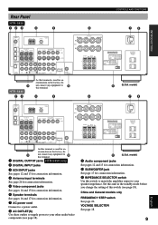
... 1OUT MONITOR OUT VIDEO R R SUB WOOFER L AUX CD IN(PLAY) OUT(REC) MD/CD-R DVD D-TV/CBL AUDIO SIGNAL R IN OUT VCR 1 SUB WOOFER OUTPUT R+ A SPEAKERS - - +L MAIN B CENTER REAR R (SURROUND) L + - IMPEDANCE SELECTOR SET BEFORE POWER ON MAIN A OR B: 8 MIN. /SPEAKER A + B:16 MIN. /SPEAKER CENTER : 8 MIN. /SPEAKER REAR : 8 MIN. /SPEAKER MAIN A OR B: 4 MIN. /SPEAKER A + B: 8 MIN. /SPEAKER CENTER : 6 MIN. /SPEAKER REAR : 6 MIN. /SPEAKER AC OUTLETS SWITCHED 100W MAX. model) 9 Audio component jacks See pages 12 and 13 for connection information. 0 SUBWOOFER jack See...
... 1OUT MONITOR OUT VIDEO R R SUB WOOFER L AUX CD IN(PLAY) OUT(REC) MD/CD-R DVD D-TV/CBL AUDIO SIGNAL R IN OUT VCR 1 SUB WOOFER OUTPUT R+ A SPEAKERS - - +L MAIN B CENTER REAR R (SURROUND) L + - IMPEDANCE SELECTOR SET BEFORE POWER ON MAIN A OR B: 8 MIN. /SPEAKER A + B:16 MIN. /SPEAKER CENTER : 8 MIN. /SPEAKER REAR : 8 MIN. /SPEAKER MAIN A OR B: 4 MIN. /SPEAKER A + B: 8 MIN. /SPEAKER CENTER : 6 MIN. /SPEAKER REAR : 6 MIN. /SPEAKER AC OUTLETS SWITCHED 100W MAX. model) 9 Audio component jacks See pages 12 and 13 for connection information. 0 SUBWOOFER jack See...
Owner's Manual
Page 21
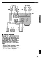
... system Center speaker Right Left Rear speakers I Subwoofer connection When using this jack. INTRODUCTION PREPARATION BASIC OPERATION ADVANCED OPERATION Main speakers A Main speakers B CONNECTIONS Right Left Right R+ A SPEAKERS - - +L MAIN B CENTER REAR R (SURROUND) L + - TOTAL Left (HTR-5450/U.S.A. SET)" and "6 DTS SET" in the SET MENU, some signals may not be output from the main, center and/or rear channels are directed to this jack. (The cut-off frequency of this jack is 90 Hz.) The LFE (low-frequency effect) signals generated when Dolby Digital or DTS is...
... system Center speaker Right Left Rear speakers I Subwoofer connection When using this jack. INTRODUCTION PREPARATION BASIC OPERATION ADVANCED OPERATION Main speakers A Main speakers B CONNECTIONS Right Left Right R+ A SPEAKERS - - +L MAIN B CENTER REAR R (SURROUND) L + - TOTAL Left (HTR-5450/U.S.A. SET)" and "6 DTS SET" in the SET MENU, some signals may not be output from the main, center and/or rear channels are directed to this jack. (The cut-off frequency of this jack is 90 Hz.) The LFE (low-frequency effect) signals generated when Dolby Digital or DTS is...
Owner's Manual
Page 23
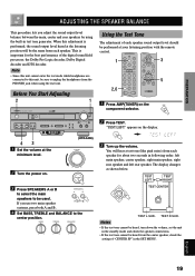
... test tone generator. Before You Start Adjusting 2 1 STANDBY /ON D I G I TA L SURROUND BASS TREBLE BALANCE -+ -+ L R SPEAKERS A B ON OFF D I G I TA L VOLUME PROGRAM EFFECT PRESET/TUNING PHONES S VIDEO VIDEO L AUDIO R OPTICAL A/B/C/D/E PRESET /TUNING FM/AM EDIT MEMORY TUNING MODE MAN'L/AUTO FM AUTO/MAN'L MONO INPUT MODE INPUT 6CH INPUT SILENT VIDEO AUX 43 1 Set the volume at your listening position with the remote control. 1 3 5 2,6 1 Press AMP(TUNER) on the component selector. 2 Press TEST. TEST R SUR. This is performed, the sound output level...
... test tone generator. Before You Start Adjusting 2 1 STANDBY /ON D I G I TA L SURROUND BASS TREBLE BALANCE -+ -+ L R SPEAKERS A B ON OFF D I G I TA L VOLUME PROGRAM EFFECT PRESET/TUNING PHONES S VIDEO VIDEO L AUDIO R OPTICAL A/B/C/D/E PRESET /TUNING FM/AM EDIT MEMORY TUNING MODE MAN'L/AUTO FM AUTO/MAN'L MONO INPUT MODE INPUT 6CH INPUT SILENT VIDEO AUX 43 1 Set the volume at your listening position with the remote control. 1 3 5 2,6 1 Press AMP(TUNER) on the component selector. 2 Press TEST. TEST R SUR. This is performed, the sound output level...
Owner's Manual
Page 26
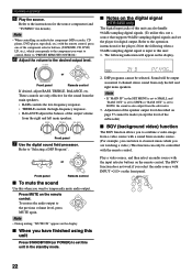
... on the display. DSP programs cannot be output as normal 2-channel stereo sound from the subwoofer. 3. Note • When controlling an audio/video component (MD recorder, CD player, DVD player, tape deck, etc.) with the input selector buttons on the front panel. 22 BASS TREBLE BALANCE -+ -+ L R Front panel 7 Use the digital sound field processor. Refer to the desired output level. PROGRAM or Front panel Remote control I Notes on the digital signal HTR-5450 only The digital input jacks of the subwoofer) I When you to set this unit Press STANDBY/ON (or POWER) to...
... on the display. DSP programs cannot be output as normal 2-channel stereo sound from the subwoofer. 3. Note • When controlling an audio/video component (MD recorder, CD player, DVD player, tape deck, etc.) with the input selector buttons on the front panel. 22 BASS TREBLE BALANCE -+ -+ L R Front panel 7 Use the digital sound field processor. Refer to the desired output level. PROGRAM or Front panel Remote control I Notes on the digital signal HTR-5450 only The digital input jacks of the subwoofer) I When you to set this unit Press STANDBY/ON (or POWER) to...
Owner's Manual
Page 28
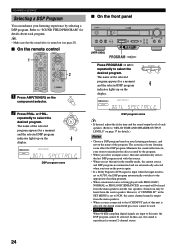
... SET MENU is set to "DELAY TIME AND SPEAKER OUTPUT LEVELS" on page 37 for a moment and the selected DSP program indicator lights up on the power again. • If a Dolby Digital or DTS signal is input when the input mode is set this unit is reproduced as normal 2-channel stereo. 24 PLAYING A SOURCE Selecting a DSP Program You can only be selected. In this case, the sound is selected, the digital sound field processor cannot be used with that the sound effect is being played with PRO...
... SET MENU is set to "DELAY TIME AND SPEAKER OUTPUT LEVELS" on page 37 for a moment and the selected DSP program indicator lights up on the power again. • If a Dolby Digital or DTS signal is input when the input mode is set this unit is reproduced as normal 2-channel stereo. 24 PLAYING A SOURCE Selecting a DSP Program You can only be selected. In this case, the sound is selected, the digital sound field processor cannot be used with that the sound effect is being played with PRO...
Owner's Manual
Page 35
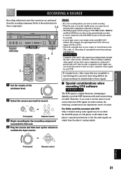
... DSP program and the setting of VOLUME, BASS, TREBLE and BALANCE have DTS signals recorded on them, the following considerations and adjustments need to be recorded. Refer to those signals. For DVDs and CDs encoded with DTS Only 2-channel analog audio signals may be disturbed due to the instructions for these components. 1,4 STANDBY /ON D I G I TA L SURROUND BASS TREBLE BALANCE -+ -+ L R SPEAKERS A B ON OFF (HTR-5450) D I G I Special considerations when recording DTS software HTR-5450 only The DTS signal is a digital bitstream. Front panel 2 Select the source...
... DSP program and the setting of VOLUME, BASS, TREBLE and BALANCE have DTS signals recorded on them, the following considerations and adjustments need to be recorded. Refer to those signals. For DVDs and CDs encoded with DTS Only 2-channel analog audio signals may be disturbed due to the instructions for these components. 1,4 STANDBY /ON D I G I TA L SURROUND BASS TREBLE BALANCE -+ -+ L R SPEAKERS A B ON OFF (HTR-5450) D I G I Special considerations when recording DTS software HTR-5450 only The DTS signal is a digital bitstream. Front panel 2 Select the source...
Owner's Manual
Page 37
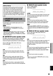
... main speakers. All of "1 SPEAKER SET" are not affected (except "MAIN LVL"). • HTR-5450 only When 96-kHz sampling digital signals are input to this unit, level adjustments in items "MAIN SP", "BASS OUT" and "MAIN LVL" are possible, but those in the standby mode, the power cord is disconnected from the AC outlet, or the power supply is directed to the speakers selected with "BASS OUT". NON Select...
... main speakers. All of "1 SPEAKER SET" are not affected (except "MAIN LVL"). • HTR-5450 only When 96-kHz sampling digital signals are input to this unit, level adjustments in items "MAIN SP", "BASS OUT" and "MAIN LVL" are possible, but those in the standby mode, the power cord is disconnected from the AC outlet, or the power supply is directed to the speakers selected with "BASS OUT". NON Select...
Owner's Manual
Page 39
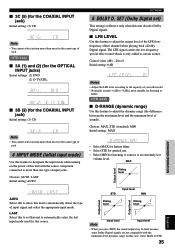
... set ) This setting is most suitable for listening at an extremely low volume level. HTR-5440 I LFE LEVEL Use this unit to sources at home. I 3C (5) (for the COAXIAL INPUT jack) Initial setting: (5) CD Note • You cannot select an item more than one type of input jacks. SET (Dolby Digital set this feature to -8 dB is effective only when this unit decodes Dolby Digital signals. Control value (dB): -20 to 0 Initial setting: 0 dB dB Notes • Adjust the LFE level...
... set ) This setting is most suitable for listening at an extremely low volume level. HTR-5440 I LFE LEVEL Use this unit to sources at home. I 3C (5) (for the COAXIAL INPUT jack) Initial setting: (5) CD Note • You cannot select an item more than one type of input jacks. SET (Dolby Digital set this feature to -8 dB is effective only when this unit decodes Dolby Digital signals. Control value (dB): -20 to 0 Initial setting: 0 dB dB Notes • Adjust the LFE level...
Owner's Manual
Page 40
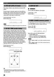
... output level of the center channel sound. This feature works when this unit. However, in most home situations, the center speaker is only added to certain scenes. The LFE signal carries the low-frequency special effect sound which is placed in line with the main speakers. Adjusting the delay time for giving depth to the dialog. GUARD" is especially important for the center speaker is set to ON, you cannot use the test tone...
... output level of the center channel sound. This feature works when this unit. However, in most home situations, the center speaker is only added to certain scenes. The LFE signal carries the low-frequency special effect sound which is placed in line with the main speakers. Adjusting the delay time for giving depth to the dialog. GUARD" is especially important for the center speaker is set to ON, you cannot use the test tone...
Owner's Manual
Page 44
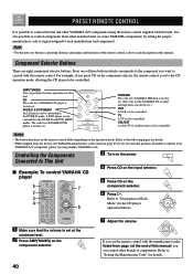
... component selector. 6 Press p. Controlling the Components Connected to This Unit I Example: To control YAMAHA CD player 5 7 2 3 4 6 3 Turn on the power. 4 Press CD on the input selector. 5 Press CD on the operation mode. It is also possible to control components from the factory, the YAMAHA manufacturer codes listed on the component selector. 40 7 Adjust the volume. A DVD player can control other brands of the remote control, refer to each manufacturer and component). CBL/SAT A cable TV or satellite tuner...
... component selector. 6 Press p. Controlling the Components Connected to This Unit I Example: To control YAMAHA CD player 5 7 2 3 4 6 3 Turn on the power. 4 Press CD on the input selector. 5 Press CD on the operation mode. It is also possible to control components from the factory, the YAMAHA manufacturer codes listed on the component selector. 40 7 Adjust the volume. A DVD player can control other brands of the remote control, refer to each manufacturer and component). CBL/SAT A cable TV or satellite tuner...
Owner's Manual
Page 49
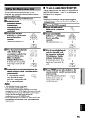
... flash, repeat step 3 and re-enter the code. 5 Press POWER (or any other button) on the remote control to enter the four-digit code for the second (and third) VCR. The code set in the DVD/LD mode is also simultaneously set in the DVD MENU mode. • If your component does not respond to any other than AMP(TUNER). 1 Turn on your component to be used. 2 Press one mode. • In the DVD...
... flash, repeat step 3 and re-enter the code. 5 Press POWER (or any other button) on the remote control to enter the four-digit code for the second (and third) VCR. The code set in the DVD/LD mode is also simultaneously set in the DVD MENU mode. • If your component does not respond to any other than AMP(TUNER). 1 Turn on your component to be used. 2 Press one mode. • In the DVD...
Owner's Manual
Page 50
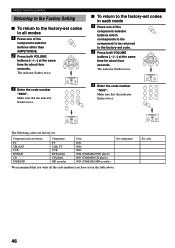
PRESET REMOTE CONTROL Returning to the Factory Setting I To return to the factory-set . Make sure that the indicator flashes twice. 3 Enter the code number "0000". The indicator flashes twice. The indicator flashes twice. 3 Enter the code number "9990". Component selector button TV CBL/SAT VCR DVD/LD CD TAPE/MD Component TV Cable TV VCR DVD player CD player MD recorder Code 0101 0006 0002 0008 (YAMAHA DVD player) 0005 (YAMAHA CD player) 0024 (YAMAHA MD recorder) Set component We recommend that...
PRESET REMOTE CONTROL Returning to the Factory Setting I To return to the factory-set . Make sure that the indicator flashes twice. 3 Enter the code number "0000". The indicator flashes twice. The indicator flashes twice. 3 Enter the code number "9990". Component selector button TV CBL/SAT VCR DVD/LD CD TAPE/MD Component TV Cable TV VCR DVD player CD player MD recorder Code 0101 0006 0002 0008 (YAMAHA DVD player) 0005 (YAMAHA CD player) 0024 (YAMAHA MD recorder) Set component We recommend that...
Owner's Manual
Page 54
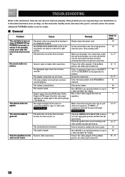
... PCM audio, Dolby Digital or DTS signal which this unit cannot reproduce are connected to this unit in the standby mode. If the problem persists, the cables may be heard. The protection circuit has been activated. Secure the connections. Turn on . If the problem you are not secure. HTR-5450 only The protection circuit has been activated because of video jacks. Select the main speakers with INPUT l / h or 6CH INPUT (or the input selector buttons...
... PCM audio, Dolby Digital or DTS signal which this unit cannot reproduce are connected to this unit in the standby mode. If the problem persists, the cables may be heard. The protection circuit has been activated. Secure the connections. Turn on . If the problem you are not secure. HTR-5450 only The protection circuit has been activated because of video jacks. Select the main speakers with INPUT l / h or 6CH INPUT (or the input selector buttons...
Owner's Manual
Page 62
... BGV function 22 C CBL/SAT mode 44 CD mode 42 CINEMA DSP 47, 56 Connections Antennas 26 Audio components (MD recorder, CD recorder and CD player 12 External decoder 12 Power supply cords 18 Speakers 16 Video components (DVD player, VCR and TV/digital TV or cable TV/satellite tuner 14 D Delay time 37 Display 8 DISPLAY SET (SET MENU 36 DOLBY D. SET (SET MENU) D-RANGE 35 LFE LEVEL 35 Dolby Digital 56 Dolby Surround (Dolby Pro Logic 56 DSP program CINEMA DSP program 47 Hi-Fi DSP program 47 DTS 56 DTS SET (SET MENU 36 Dust protection cap 12 DVD/LD mode 43 DVD MENU mode 43...
... BGV function 22 C CBL/SAT mode 44 CD mode 42 CINEMA DSP 47, 56 Connections Antennas 26 Audio components (MD recorder, CD recorder and CD player 12 External decoder 12 Power supply cords 18 Speakers 16 Video components (DVD player, VCR and TV/digital TV or cable TV/satellite tuner 14 D Delay time 37 Display 8 DISPLAY SET (SET MENU 36 DOLBY D. SET (SET MENU) D-RANGE 35 LFE LEVEL 35 Dolby Digital 56 Dolby Surround (Dolby Pro Logic 56 DSP program CINEMA DSP program 47 Hi-Fi DSP program 47 DTS 56 DTS SET (SET MENU 36 Dust protection cap 12 DVD/LD mode 43 DVD MENU mode 43...


