

Owner's Manual
Page 1
POWER AMPLIFIER Owner's Manual POWER TEMP PROTECTION POWER ON OFF POWER AMPLIFIER 20 15 L CLIP R 20 15 25 10 25 10 30 LEVEL 30 6 6 40 3 40 3 0 L -dB 0 R Keep This Manual For Future Reference. E
POWER AMPLIFIER Owner's Manual POWER TEMP PROTECTION POWER ON OFF POWER AMPLIFIER 20 15 L CLIP R 20 15 25 10 25 10 30 LEVEL 30 6 6 40 3 40 3 0 L -dB 0 R Keep This Manual For Future Reference. E
Owner's Manual
Page 3
.... • Do not scratch, bend, twist, pull, or heat the power cord. Dirty contacts may generate heat. • Use only speaker cables when connecting speakers to amplifier outputs. If you continue using the CP2000 Warnings • Do not allow water to enter this unit. Blocked ventilation... unit will heat up inside the unit, turn the power switch off immediately. Using other than driving loudspeakers. If you notice any purpose other types of this unit or allow enough free space around the unit for repair. CP2000-Owner's Manual If the airflow is necessary,...
.... • Do not scratch, bend, twist, pull, or heat the power cord. Dirty contacts may generate heat. • Use only speaker cables when connecting speakers to amplifier outputs. If you continue using the CP2000 Warnings • Do not allow water to enter this unit. Blocked ventilation... unit will heat up inside the unit, turn the power switch off immediately. Using other than driving loudspeakers. If you notice any purpose other types of this unit or allow enough free space around the unit for repair. CP2000-Owner's Manual If the airflow is necessary,...
Owner's Manual
Page 4
... 11 Daisy Chaining Inputs 12 Troubleshooting 13 Appendix 14 Specifications 14 Dimensions 15 Block Diagram 16 CP2000-Owner's Manual All other trademarks are hereby acknowledged. ii Contents Package Contents The CP2000 package should contain the following items. Contact your Yamaha dealer if anything is missing. • CP2000 Power Amplifier • This manual Trademarks...
... 11 Daisy Chaining Inputs 12 Troubleshooting 13 Appendix 14 Specifications 14 Dimensions 15 Block Diagram 16 CP2000-Owner's Manual All other trademarks are hereby acknowledged. ii Contents Package Contents The CP2000 package should contain the following items. Contact your Yamaha dealer if anything is missing. • CP2000 Power Amplifier • This manual Trademarks...
Owner's Manual
Page 5
...jack output connectors. • Signal and CLIP indicators on a new improved version of Yamaha's EEEngine amplifier technology, the CP2000 is a versatile two-channel power amplifier, offering high-power, superb sonic performance, and reliability, all backed by up to 50% and cut...8486; bridged. • Yamaha Speaker Processing matches the CP2000 to 35%. • Built-in which both amplifier and speakers if heatsink overheating occurs or a DC offset is idle, the fan stops for choosing the Yamaha CP2000 Power Amplifier. While the CP2000 is detected at the outputs...
...jack output connectors. • Signal and CLIP indicators on a new improved version of Yamaha's EEEngine amplifier technology, the CP2000 is a versatile two-channel power amplifier, offering high-power, superb sonic performance, and reliability, all backed by up to 50% and cut...8486; bridged. • Yamaha Speaker Processing matches the CP2000 to 35%. • Built-in which both amplifier and speakers if heatsink overheating occurs or a DC offset is idle, the fan stops for choosing the Yamaha CP2000 Power Amplifier. While the CP2000 is detected at the outputs...
Owner's Manual
Page 6
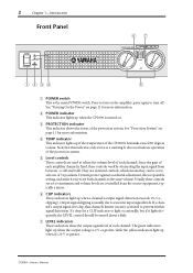
... these controls are set to maximum and volume levels are controlled from between -∞ dB and 0 dB. B POWER indicator This indicator lights up when the CP2000 is activated to excessive input signal levels. Note that channel's limiter circuit is turned on page 11 for more information...it lights frequently, the LEVEL control should be turned down a little. See "Turning On the Power" on . G LEVEL indicators These indicators show the output signal level of each channel. CP2000-Owner's Manual Press to adjust the volume level of each channel. See "Protection System" on...
... these controls are set to maximum and volume levels are controlled from between -∞ dB and 0 dB. B POWER indicator This indicator lights up when the CP2000 is activated to excessive input signal levels. Note that channel's limiter circuit is turned on page 11 for more information...it lights frequently, the LEVEL control should be turned down a little. See "Turning On the Power" on . G LEVEL indicators These indicators show the output signal level of each channel. CP2000-Owner's Manual Press to adjust the volume level of each channel. See "Protection System" on...
Owner's Manual
Page 8
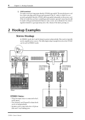
... this terminal to a good ground point or the chassis of the AC outlet to which it 's important that the CP2000 is grounded. The attached power cord has a three-pin plug, and if the ground terminal of the mixer, preamp, etc. 2 Hookup Examples ...Stereo Hookup In STEREO mode, the L and R channels operate independently. This mode is typically used in STEREO mode. STEREO BRIDGE PARALLEL CHANNEL R 2 1 3 INPUT STEREO BRIDGE PARALLEL OFF ON CHANNEL L (BRIDGE) NEUTRIK 2 1 3 YAMAHA...
... this terminal to a good ground point or the chassis of the AC outlet to which it 's important that the CP2000 is grounded. The attached power cord has a three-pin plug, and if the ground terminal of the mixer, preamp, etc. 2 Hookup Examples ...Stereo Hookup In STEREO mode, the L and R channels operate independently. This mode is typically used in STEREO mode. STEREO BRIDGE PARALLEL CHANNEL R 2 1 3 INPUT STEREO BRIDGE PARALLEL OFF ON CHANNEL L (BRIDGE) NEUTRIK 2 1 3 YAMAHA...
Owner's Manual
Page 13
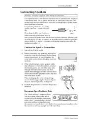
... in such a way that they may cause a short. When attaching speaker cables with the correct polarity, otherwise, the sound qual- CP2000-Owner's Manual Be sure to the binding post labelled (-). When connecting an external wire to this terminal, it is necessary either to ... Speakers 9 Connecting Speakers Warning: Turn off all equipment before making your connections. 3 When attaching bare-ended speaker cables, strip off the POWER switch. 2 Before connecting any connections. For optimum performance, use leads or a cord that have been manufactured in the posts, and then...
... in such a way that they may cause a short. When attaching speaker cables with the correct polarity, otherwise, the sound qual- CP2000-Owner's Manual Be sure to the binding post labelled (-). When connecting an external wire to this terminal, it is necessary either to ... Speakers 9 Connecting Speakers Warning: Turn off all equipment before making your connections. 3 When attaching bare-ended speaker cables, strip off the POWER switch. 2 Before connecting any connections. For optimum performance, use leads or a cord that have been manufactured in the posts, and then...
Owner's Manual
Page 15
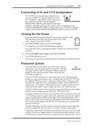
... (especially the 115IV). In addition to allowing the protection system to OFF. Once the heatsink has cooled down . The POWER indicator goes out. OFF ON mizes the CP2000 for best performance the YAMAHA SPEAKER PROCESSING switch should be set to perform various checks, protects the speakers against damage due to ON. When using...
... (especially the 115IV). In addition to allowing the protection system to OFF. Once the heatsink has cooled down . The POWER indicator goes out. OFF ON mizes the CP2000 for best performance the YAMAHA SPEAKER PROCESSING switch should be set to perform various checks, protects the speakers against damage due to ON. When using...
Owner's Manual
Page 16
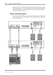
..., reconnecting the power, the POWER indicator lights up, and normal operation is resumed. CHANNEL R 2 1 3 INPUT STEREO BRIDGE PARALLEL OFF ON CHANNEL L (BRIDGE) NEUTRIK 2 1 3 YAMAHA SPEAKER PROCESSING 2 1 1 2 CHANNEL R (-) BRIDGE (+) SPEAKERS CHANNEL L CHANNEL R 2 1 3 INPUT STEREO BRIDGE PARALLEL OFF ON CHANNEL L (BRIDGE) NEUTRIK 2 1 3 YAMAHA SPEAKER PROCESSING ST OUT Mixer CP2000-Owner's Manual ...;ers by daisy chaining the inputs, as shown below. 12 Chapter 3-Using the CP2000 disconnects the AC power when the transformer reaches a certain temperature and the...
..., reconnecting the power, the POWER indicator lights up, and normal operation is resumed. CHANNEL R 2 1 3 INPUT STEREO BRIDGE PARALLEL OFF ON CHANNEL L (BRIDGE) NEUTRIK 2 1 3 YAMAHA SPEAKER PROCESSING 2 1 1 2 CHANNEL R (-) BRIDGE (+) SPEAKERS CHANNEL L CHANNEL R 2 1 3 INPUT STEREO BRIDGE PARALLEL OFF ON CHANNEL L (BRIDGE) NEUTRIK 2 1 3 YAMAHA SPEAKER PROCESSING ST OUT Mixer CP2000-Owner's Manual ...;ers by daisy chaining the inputs, as shown below. 12 Chapter 3-Using the CP2000 disconnects the AC power when the transformer reaches a certain temperature and the...
Owner's Manual
Page 17
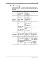
... control settings. There is in which they may light up, and what action to take if and when they do. CP2000-Owner's Manual Symptom POWER indicator not lit No sound Stereo sources sound odd CLIP indicator lit TEMP indicator lit PROTECTION indicator lit Possible Cause...temperature has exceeded 85˚C. Locate and remove the short. Make sure that 2Ω (STEREO/PARALLEL) or 4Ω (BRIDGE). - - - Contact your Yamaha dealer or service center. A DC offset of ±2 V or more was detected at the speaker terminals, amplifier terminals, or in the speaker ...
... control settings. There is in which they may light up, and what action to take if and when they do. CP2000-Owner's Manual Symptom POWER indicator not lit No sound Stereo sources sound odd CLIP indicator lit TEMP indicator lit PROTECTION indicator lit Possible Cause...temperature has exceeded 85˚C. Locate and remove the short. Make sure that 2Ω (STEREO/PARALLEL) or 4Ω (BRIDGE). - - - Contact your Yamaha dealer or service center. A DC offset of ±2 V or more was detected at the speaker terminals, amplifier terminals, or in the speaker ...
Owner's Manual
Page 18
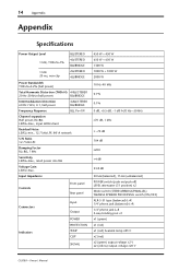
... dB 104 dB ≥200 +4 dB 33.8 dB 30 kΩ (balanced), 15 kΩ (unbalanced) POWER switch (push on/push off) LEVEL attenuator (31 position) x2 Mode switch (STEREO/BRIDGE/PARALLEL) YAMAHA SPEAKER PROCESSING switch (ON/OFF) XLR-3-31 type (balanced) L+R 1/4" phone jack (balanced) L+R 1/4" phone ...jack L+R 5-way binding post x1 x1 (green) x1 (red) x1 (red) heatsink temp ≥85°C x2 (red) x2 (green) output voltage ≥2 V x2 (yellow) output voltage ≥20 V CP2000...
... dB 104 dB ≥200 +4 dB 33.8 dB 30 kΩ (balanced), 15 kΩ (unbalanced) POWER switch (push on/push off) LEVEL attenuator (31 position) x2 Mode switch (STEREO/BRIDGE/PARALLEL) YAMAHA SPEAKER PROCESSING switch (ON/OFF) XLR-3-31 type (balanced) L+R 1/4" phone jack (balanced) L+R 1/4" phone ...jack L+R 5-way binding post x1 x1 (green) x1 (red) x1 (red) heatsink temp ≥85°C x2 (red) x2 (green) output voltage ≥2 V x2 (yellow) output voltage ≥20 V CP2000...
Owner's Manual
Page 19
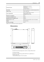
..., E3 and E4 CP2000-Owner's Manual For European Model Purchaser/User Information specified in EN55103-1 and EN55103-2. Dimensions 15 Protection Circuit Fan Circuit Limiter Circuit Power requirements Idle Power Consumption 1/8 Power Consumption (4Ω) Maximum Power Consumption (4Ω) Dimensions (W × H × D) Weight AC Power cord length 0 dB=0.775 V rms, half power=1/2 power output level POWER switch on/off...
..., E3 and E4 CP2000-Owner's Manual For European Model Purchaser/User Information specified in EN55103-1 and EN55103-2. Dimensions 15 Protection Circuit Fan Circuit Limiter Circuit Power requirements Idle Power Consumption 1/8 Power Consumption (4Ω) Maximum Power Consumption (4Ω) Dimensions (W × H × D) Weight AC Power cord length 0 dB=0.775 V rms, half power=1/2 power output level POWER switch on/off...
Owner's Manual
Page 20
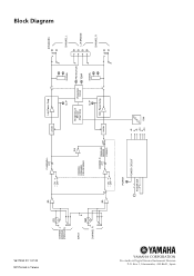
Box 3, Hamamatsu, 430-8651, Japan V617350 R1 1 IP 20 NP Printed in Taiwan CHANNEL L (BRIDGE) (PARALLEL) INPUT CHANNEL R BA CHANNEL L ATT • ON • OFF INV YAMAHA SPEAKER PROCESSING BA CHANNEL ATT R PARALLEL BRIDGE • ON • OFF STEREO POWER POWER CIRCUIT POWER SW Limiter Lch Power Amp CLIP Temperature Sensor (Heat Sink) Protection Circuit CLIP SIGNAL PROTECTION TEMP SIGNAL Limiter Rch Power Amp +B E -B +24 E -24 FAN SPEAKERS CHANNEL L L+R BRIDGE CHANNEL R Block Diagram YAMAHA CORPORATION Pro Audio & Digital Musical Instrument Division P.O.
Box 3, Hamamatsu, 430-8651, Japan V617350 R1 1 IP 20 NP Printed in Taiwan CHANNEL L (BRIDGE) (PARALLEL) INPUT CHANNEL R BA CHANNEL L ATT • ON • OFF INV YAMAHA SPEAKER PROCESSING BA CHANNEL ATT R PARALLEL BRIDGE • ON • OFF STEREO POWER POWER CIRCUIT POWER SW Limiter Lch Power Amp CLIP Temperature Sensor (Heat Sink) Protection Circuit CLIP SIGNAL PROTECTION TEMP SIGNAL Limiter Rch Power Amp +B E -B +24 E -24 FAN SPEAKERS CHANNEL L L+R BRIDGE CHANNEL R Block Diagram YAMAHA CORPORATION Pro Audio & Digital Musical Instrument Division P.O.


