

Owner's Manual
Page 1
E POWER AMPLIFIER Owner's Manual POWER TEMP PROTECTION POWER ON OFF POWER AMPLIFIER 20 15 L CLIP R 20 15 25 10 25 10 30 LEVEL 30 6 6 40 3 40 3 0 L -dB 0 R Keep This Manual For Future Reference.
E POWER AMPLIFIER Owner's Manual POWER TEMP PROTECTION POWER ON OFF POWER AMPLIFIER 20 15 L CLIP R 20 15 25 10 25 10 30 LEVEL 30 6 6 40 3 40 3 0 L -dB 0 R Keep This Manual For Future Reference.
Owner's Manual
Page 2
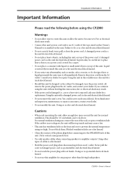
...plug, proceed as follows: The wire which is coloured GREEN and YELLOW must be connected to products distributed by the safety earth symbol or coloured GREEN and YELLOW. WARNING: THIS APPARATUS MUST BE EARTHED IMPORTANT THE WIRES IN THIS MAINS LEAD ARE COLOURED IN ACCORDANCE WITH THE FOLLOWING CODE... with the letter N or coloured BLACK. The wire which is coloured BROWN must be connected to the terminal which is marked with the letter L or coloured RED. * This applies only to the terminal in the plug which is marked by the letter E or by YAMAHA KEMBLE MUSIC (U.K.) LTD.
...plug, proceed as follows: The wire which is coloured GREEN and YELLOW must be connected to products distributed by the safety earth symbol or coloured GREEN and YELLOW. WARNING: THIS APPARATUS MUST BE EARTHED IMPORTANT THE WIRES IN THIS MAINS LEAD ARE COLOURED IN ACCORDANCE WITH THE FOLLOWING CODE... with the letter N or coloured BLACK. The wire which is coloured BROWN must be connected to the terminal which is marked with the letter L or coloured RED. * This applies only to the terminal in the plug which is marked by the letter E or by YAMAHA KEMBLE MUSIC (U.K.) LTD.
Owner's Manual
Page 3
... the unit, turn the power switch off immediately. Dirty contacts may result. • If the power cord is damaged (i.e., cut or a bare wire is a fire and electrical shock hazard. • Do not place heavy objects, including this instruction, fire or electrical shock may generate heat. • Use only speaker cables when connecting speakers to place heavy objects on a power cord covered by...
... the unit, turn the power switch off immediately. Dirty contacts may result. • If the power cord is damaged (i.e., cut or a bare wire is a fire and electrical shock hazard. • Do not place heavy objects, including this instruction, fire or electrical shock may generate heat. • Use only speaker cables when connecting speakers to place heavy objects on a power cord covered by...
Owner's Manual
Page 4
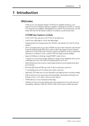
All rights reserved. Contents 1 Introduction 1 Welcome 1 Front Panel 2 Rear Panel 3 2 Hookup Examples 4 Stereo Hookup 4 Parallel Hookup 5 Bridge Mode Hookup 6 3 Using the CP2000 7 Installation 7 Connecting Inputs 7 Connecting Speakers 9 Connecting S115 and S112 loudspeakers 11 Turning On the Power 11 Protection System 11 Daisy Chaining Inputs 12 Troubleshooting 13 Appendix 14 Specifications 14 Dimensions 15 Block Diagram 16 CP2000-Owner's Manual Copyright No part of this Owner's Manual may be reproduced or distributed in any form or by any means without the prior...
All rights reserved. Contents 1 Introduction 1 Welcome 1 Front Panel 2 Rear Panel 3 2 Hookup Examples 4 Stereo Hookup 4 Parallel Hookup 5 Bridge Mode Hookup 6 3 Using the CP2000 7 Installation 7 Connecting Inputs 7 Connecting Speakers 9 Connecting S115 and S112 loudspeakers 11 Turning On the Power 11 Protection System 11 Daisy Chaining Inputs 12 Troubleshooting 13 Appendix 14 Specifications 14 Dimensions 15 Block Diagram 16 CP2000-Owner's Manual Copyright No part of this Owner's Manual may be reproduced or distributed in any form or by any means without the prior...
Owner's Manual
Page 5
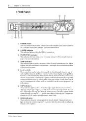
... balanced XLR-type and 1/4" phone jack input connectors. • 5-way binding posts and 1/4" phone jack output connectors. • Signal and CLIP indicators on each channel provide signal presence and clip warning. • Relay-based protection system protects both amplifier and speakers if heatsink overheating occurs or a DC offset is idle, the fan stops for choosing the Yamaha CP2000 Power Amplifier. CP2000...
... balanced XLR-type and 1/4" phone jack input connectors. • 5-way binding posts and 1/4" phone jack output connectors. • Signal and CLIP indicators on each channel provide signal presence and clip warning. • Relay-based protection system protects both amplifier and speakers if heatsink overheating occurs or a DC offset is idle, the fan stops for choosing the Yamaha CP2000 Power Amplifier. CP2000...
Owner's Manual
Page 6
... for more information. They are used to adjust the volume level of each channel. Usually these controls work by attenuating the input signal from the source equipment, typically a mixer. F CLIP indicators These indicators light up if the temperature of 31 positions. CP2000-Owner's Manual Press to turn off. D TEMP indicator This indicator lights up when a channel's output signal distortion exceeds 1% (i.e., clipping). E Level controls These controls are detented controls, which means they can be...
... for more information. They are used to adjust the volume level of each channel. Usually these controls work by attenuating the input signal from the source equipment, typically a mixer. F CLIP indicators These indicators light up if the temperature of 31 positions. CP2000-Owner's Manual Press to turn off. D TEMP indicator This indicator lights up when a channel's output signal distortion exceeds 1% (i.e., clipping). E Level controls These controls are detented controls, which means they can be...
Owner's Manual
Page 7
... watt single-channel amplifier. STEREO-In this mode, the L and R channels are used, this mode, the L and R channels operate independently but the input signal for both channels is sourced from the Channel L inputs, the volume level is sourced from the Channel L inputs. The 1/4" phone jacks accept 1/4" phone plugs, while the 5-way binding posts offer several methods of 5-way binding posts. CP2000-Owner's Manual See also "Hookup Examples" on page 12 for more information. C YAMAHA SPEAKER PROCESSING switch...
... watt single-channel amplifier. STEREO-In this mode, the L and R channels are used, this mode, the L and R channels operate independently but the input signal for both channels is sourced from the Channel L inputs, the volume level is sourced from the Channel L inputs. The 1/4" phone jacks accept 1/4" phone plugs, while the 5-way binding posts offer several methods of 5-way binding posts. CP2000-Owner's Manual See also "Hookup Examples" on page 12 for more information. C YAMAHA SPEAKER PROCESSING switch...
Owner's Manual
Page 8
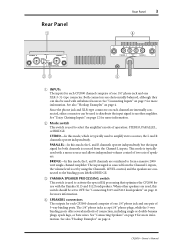
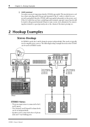
... R channels operate independently. If hum or noise occurs, try to eliminate it by connecting this ground terminal. 4 Chapter 2-Hookup Examples E GND terminal For safety reasons it's important that the CP2000 is connected to the L and R inputs. • The Channel L and Channel R volume levels can be set independently. • Speakers can be used to amplify stereo sources. This mode is grounded, then the CP2000 will be grounded adequately via the power cord...
... R channels operate independently. If hum or noise occurs, try to eliminate it by connecting this ground terminal. 4 Chapter 2-Hookup Examples E GND terminal For safety reasons it's important that the CP2000 is connected to the L and R inputs. • The Channel L and Channel R volume levels can be set independently. • Speakers can be used to amplify stereo sources. This mode is grounded, then the CP2000 will be grounded adequately via the power cord...
Owner's Manual
Page 9
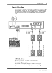
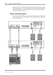
The following hookup example shows how the CP2000 can be used with a mono source and allows independent volume control of two sets of speakers. CP2000-Owner's Manual Parallel Hookup 5 Parallel Hookup In PARALLEL mode, the L and R channels operate independently but the input signal for both channels is typically used in PARALLEL mode. STEREO BRIDGE PARALLEL CHANNEL R 2 1 3 INPUT STEREO BRIDGE PARALLEL OFF ON CHANNEL L (BRIDGE) NEUTRIK 2 1 3 YAMAHA SPEAKER PROCESSING MONO OUT 2 1 1 2 CHANNEL R (-) BRIDGE (+) SPEAKERS CHANNEL L Total impedance: 2Ω min (1000 W) ...
The following hookup example shows how the CP2000 can be used with a mono source and allows independent volume control of two sets of speakers. CP2000-Owner's Manual Parallel Hookup 5 Parallel Hookup In PARALLEL mode, the L and R channels operate independently but the input signal for both channels is typically used in PARALLEL mode. STEREO BRIDGE PARALLEL CHANNEL R 2 1 3 INPUT STEREO BRIDGE PARALLEL OFF ON CHANNEL L (BRIDGE) NEUTRIK 2 1 3 YAMAHA SPEAKER PROCESSING MONO OUT 2 1 1 2 CHANNEL R (-) BRIDGE (+) SPEAKERS CHANNEL L Total impedance: 2Ω min (1000 W) ...
Owner's Manual
Page 10
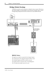
... 2 1 3 YAMAHA SPEAKER PROCESSING 2 1 1 2 CHANNEL R (-) BRIDGE (+) SPEAKERS CHANNEL L Total impedance: 4Ω min (2000 W) 8Ω (1300 W) MONO OUT Mixer BRIDGE Notes: • The input source must not be used in BRIDGE mode. CP2000-Owner's Manual 6 Chapter 2-Hookup Examples Bridge Mode Hookup In BRIDGE mode, the L and R channels are inactive. • The speakers must be connected to the 5-way binding posts. • The 1/4" phone jack outputs must be connected to the Channel L inputs. • The volume level is sourced from the Channel L inputs.
... 2 1 3 YAMAHA SPEAKER PROCESSING 2 1 1 2 CHANNEL R (-) BRIDGE (+) SPEAKERS CHANNEL L Total impedance: 4Ω min (2000 W) 8Ω (1300 W) MONO OUT Mixer BRIDGE Notes: • The input source must not be used in BRIDGE mode. CP2000-Owner's Manual 6 Chapter 2-Hookup Examples Bridge Mode Hookup In BRIDGE mode, the L and R channels are inactive. • The speakers must be connected to the 5-way binding posts. • The 1/4" phone jack outputs must be connected to the Channel L inputs. • The volume level is sourced from the Channel L inputs.
Owner's Manual
Page 11
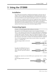
... the same channel. For correct operation, it from the rear. Connecting Inputs Warning: Turn off all equipment before using the CP2000. The inputs for input connections. Male XLR plugs should be wired as shown. The CP2000 uses a variable-speed low-noise fan to regulate the system temperature, which offer additional support and should be fixed to the rear of one 1/4" phone jack and one sound source to the front-panel rack...
... the same channel. For correct operation, it from the rear. Connecting Inputs Warning: Turn off all equipment before using the CP2000. The inputs for input connections. Male XLR plugs should be wired as shown. The CP2000 uses a variable-speed low-noise fan to regulate the system temperature, which offer additional support and should be fixed to the rear of one 1/4" phone jack and one sound source to the front-panel rack...
Owner's Manual
Page 12
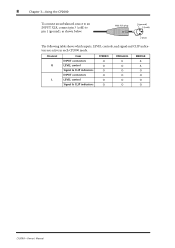
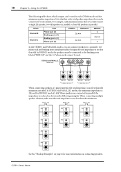
Channel R L Item INPUT connectors LEVEL control Signal & CLIP indicators INPUT connectors LEVEL control Signal & CLIP indicators STEREO O O O O O O PARALLEL X O O O O O BRIDGE X X O O O O CP2000-Owner's Manual Male XLR plug 1 (ground) 3 (cold) 2 (hot) The following table shows which inputs, LEVEL controls, and signal and CLIP indicators are active in each CP2000 mode. 8 Chapter 3-Using the CP2000 To connect an unbalanced source to an INPUT XLR, connect pin 3 (cold) to pin 1 (ground), as shown below.
Channel R L Item INPUT connectors LEVEL control Signal & CLIP indicators INPUT connectors LEVEL control Signal & CLIP indicators STEREO O O O O O O PARALLEL X O O O O O BRIDGE X X O O O O CP2000-Owner's Manual Male XLR plug 1 (ground) 3 (cold) 2 (hot) The following table shows which inputs, LEVEL controls, and signal and CLIP indicators are active in each CP2000 mode. 8 Chapter 3-Using the CP2000 To connect an unbalanced source to an INPUT XLR, connect pin 3 (cold) to pin 1 (ground), as shown below.
Owner's Manual
Page 13
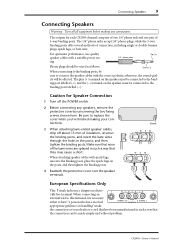
..., the sound qual- When attaching speaker cables with a suitable power rat- 1/4" phone plug ing. The 1/4" phone jacks accept 1/4" phone plugs, while the 5-way binding posts offer several methods of 5-way binding posts. The outputs for Speaker Connection 1 Turn off about 15 mm of the bare wires are splayed in the posts, and then tighten the binding posts. Caution for each CP2000 channel comprise of...
..., the sound qual- When attaching speaker cables with a suitable power rat- 1/4" phone plug ing. The 1/4" phone jacks accept 1/4" phone plugs, while the 5-way binding posts offer several methods of 5-way binding posts. The outputs for Speaker Connection 1 Turn off about 15 mm of the bare wires are splayed in the posts, and then tighten the binding posts. Caution for each CP2000 channel comprise of...
Owner's Manual
Page 14
...; 8Ω 4Ω 8Ω 8Ω See the "Hookup Examples" on connecting speakers. For example, a 2Ω minimum means that can be used . CP2000-Owner's Manual When speakers are connected in parallel, the impedance is not less than the minimum specified. In BRIDGE mode, the speakers must be used in each channel. Mode Channel R Channel L Item Phone jack (2) Binding posts (1) Binding posts (1) Phone jack (2) STEREO PARALLEL 2Ω min 2Ω min BRIDGE...
...; 8Ω 4Ω 8Ω 8Ω See the "Hookup Examples" on connecting speakers. For example, a 2Ω minimum means that can be used . CP2000-Owner's Manual When speakers are connected in parallel, the impedance is not less than the minimum specified. In BRIDGE mode, the speakers must be used in each channel. Mode Channel R Channel L Item Phone jack (2) Binding posts (1) Binding posts (1) Phone jack (2) STEREO PARALLEL 2Ω min 2Ω min BRIDGE...
Owner's Manual
Page 15
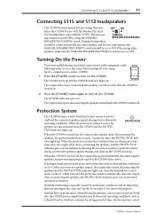
... the CP2000 and the PROTECTION indicator lights up . When the protection system is present at a speaker output, the output relay opens, disconnecting the speakers, and the PROTECTION indicator lights up . Heatsink overheating is turned on , the output relay remains open, disconnecting the speakers, for best performance the YAMAHA SPEAKER PROCESSING switch should be set to ON. When using the YAMAHA YAMAHA SPEAKER PROCESSING SPEAKER PROCESSING switch. Another layer of time, the thermostatic cutout CP2000-Owner's Manual The POWER indicator...
... the CP2000 and the PROTECTION indicator lights up . When the protection system is present at a speaker output, the output relay opens, disconnecting the speakers, and the PROTECTION indicator lights up . Heatsink overheating is turned on , the output relay remains open, disconnecting the speakers, for best performance the YAMAHA SPEAKER PROCESSING switch should be set to ON. When using the YAMAHA YAMAHA SPEAKER PROCESSING SPEAKER PROCESSING switch. Another layer of time, the thermostatic cutout CP2000-Owner's Manual The POWER indicator...
Owner's Manual
Page 16
...the POWER indicator goes out. Once the transformer has cooled down, the thermostatic cutout automatically closes, reconnecting the power, the POWER indicator lights up, and normal operation is resumed. CHANNEL R 2 1 3 INPUT STEREO BRIDGE PARALLEL OFF ON CHANNEL L (BRIDGE) NEUTRIK 2 1 3 YAMAHA SPEAKER PROCESSING 2 1 1 2 CHANNEL R (-) BRIDGE (+) SPEAKERS CHANNEL L CHANNEL R 2 1 3 INPUT STEREO BRIDGE PARALLEL OFF ON CHANNEL L (BRIDGE) NEUTRIK 2 1 3 YAMAHA SPEAKER PROCESSING ST OUT Mixer CP2000-Owner's Manual 2 1 1 2 CHANNEL R (-) BRIDGE (+) SPEAKERS CHANNEL...
...the POWER indicator goes out. Once the transformer has cooled down, the thermostatic cutout automatically closes, reconnecting the power, the POWER indicator lights up, and normal operation is resumed. CHANNEL R 2 1 3 INPUT STEREO BRIDGE PARALLEL OFF ON CHANNEL L (BRIDGE) NEUTRIK 2 1 3 YAMAHA SPEAKER PROCESSING 2 1 1 2 CHANNEL R (-) BRIDGE (+) SPEAKERS CHANNEL L CHANNEL R 2 1 3 INPUT STEREO BRIDGE PARALLEL OFF ON CHANNEL L (BRIDGE) NEUTRIK 2 1 3 YAMAHA SPEAKER PROCESSING ST OUT Mixer CP2000-Owner's Manual 2 1 1 2 CHANNEL R (-) BRIDGE (+) SPEAKERS CHANNEL...
Owner's Manual
Page 17
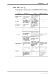
..., amplifier terminals, or in the speaker cable. Contact your Yamaha dealer or service center. Incorrect speaker polarity. Reduce the input signal level, or turn down . The limiter circuit prevents further clipping distortion. The protection circuit activates, opening the output relay and disconnecting the speakers. Input signal not connected or LEVEL controls turned down the LEVEL control. Check the input connections and LEVEL control settings. Locate and remove the short. The heatsink temperature warning circuit...
..., amplifier terminals, or in the speaker cable. Contact your Yamaha dealer or service center. Incorrect speaker polarity. Reduce the input signal level, or turn down . The limiter circuit prevents further clipping distortion. The protection circuit activates, opening the output relay and disconnecting the speakers. Input signal not connected or LEVEL controls turned down the LEVEL control. Check the input connections and LEVEL control settings. Locate and remove the short. The heatsink temperature warning circuit...
Owner's Manual
Page 18
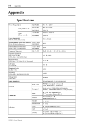
...; (unbalanced) POWER switch (push on/push off) LEVEL attenuator (31 position) x2 Mode switch (STEREO/BRIDGE/PARALLEL) YAMAHA SPEAKER PROCESSING switch (ON/OFF) XLR-3-31 type (balanced) L+R 1/4" phone jack (balanced) L+R 1/4" phone jack L+R 5-way binding post x1 x1 (green) x1 (red) x1 (red) heatsink temp ≥85°C x2 (red) x2 (green) output voltage ≥2 V x2 (yellow) output voltage ≥20 V CP2000-Owner's Manual 14 Appendix Appendix Specifications Power Output Level 8Ω/STEREO 1 kHz...
...; (unbalanced) POWER switch (push on/push off) LEVEL attenuator (31 position) x2 Mode switch (STEREO/BRIDGE/PARALLEL) YAMAHA SPEAKER PROCESSING switch (ON/OFF) XLR-3-31 type (balanced) L+R 1/4" phone jack (balanced) L+R 1/4" phone jack L+R 5-way binding post x1 x1 (green) x1 (red) x1 (red) heatsink temp ≥85°C x2 (red) x2 (green) output voltage ≥2 V x2 (yellow) output voltage ≥20 V CP2000-Owner's Manual 14 Appendix Appendix Specifications Power Output Level 8Ω/STEREO 1 kHz...
Owner's Manual
Page 19
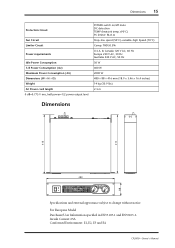
...Protection Circuit Fan Circuit Limiter Circuit Power requirements Idle Power Consumption 1/8 Power Consumption (4Ω) Maximum Power Consumption (4Ω) Dimensions (W × H × D) Weight AC Power cord length 0 dB=0.775 V rms, half power=1/2 power output level POWER switch on/off mute DC detection TEMP (heatsink temp ≥90°C) PC limiter: RL≤1Ω Stop-low... subject to change without notice. For European Model Purchaser/User Information specified in EN55103-1 and EN55103-2. Inrush Current: 65A Conformed Environment: E1, E2, E3 and E4 CP2000-Owner's Manual
...Protection Circuit Fan Circuit Limiter Circuit Power requirements Idle Power Consumption 1/8 Power Consumption (4Ω) Maximum Power Consumption (4Ω) Dimensions (W × H × D) Weight AC Power cord length 0 dB=0.775 V rms, half power=1/2 power output level POWER switch on/off mute DC detection TEMP (heatsink temp ≥90°C) PC limiter: RL≤1Ω Stop-low... subject to change without notice. For European Model Purchaser/User Information specified in EN55103-1 and EN55103-2. Inrush Current: 65A Conformed Environment: E1, E2, E3 and E4 CP2000-Owner's Manual
Owner's Manual
Page 20
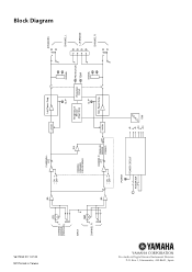
Box 3, Hamamatsu, 430-8651, Japan V617350 R1 1 IP 20 NP Printed in Taiwan CHANNEL L (BRIDGE) (PARALLEL) INPUT CHANNEL R BA CHANNEL L ATT • ON • OFF INV YAMAHA SPEAKER PROCESSING BA CHANNEL ATT R PARALLEL BRIDGE • ON • OFF STEREO POWER POWER CIRCUIT POWER SW Limiter Lch Power Amp CLIP Temperature Sensor (Heat Sink) Protection Circuit CLIP SIGNAL PROTECTION TEMP SIGNAL Limiter Rch Power Amp +B E -B +24 E -24 FAN SPEAKERS CHANNEL L L+R BRIDGE CHANNEL R Block Diagram YAMAHA CORPORATION Pro Audio & Digital Musical Instrument Division P.O.
Box 3, Hamamatsu, 430-8651, Japan V617350 R1 1 IP 20 NP Printed in Taiwan CHANNEL L (BRIDGE) (PARALLEL) INPUT CHANNEL R BA CHANNEL L ATT • ON • OFF INV YAMAHA SPEAKER PROCESSING BA CHANNEL ATT R PARALLEL BRIDGE • ON • OFF STEREO POWER POWER CIRCUIT POWER SW Limiter Lch Power Amp CLIP Temperature Sensor (Heat Sink) Protection Circuit CLIP SIGNAL PROTECTION TEMP SIGNAL Limiter Rch Power Amp +B E -B +24 E -24 FAN SPEAKERS CHANNEL L L+R BRIDGE CHANNEL R Block Diagram YAMAHA CORPORATION Pro Audio & Digital Musical Instrument Division P.O.


