

Owner's Manual
Page 1
POWER AMPLIFIER Owner's Manual POWER TEMP PROTECTION POWER ON OFF POWER AMPLIFIER 20 15 L CLIP R 20 15 25 10 25 10 30 LEVEL 30 6 6 40 3 40 3 0 L -dB 0 R Keep This Manual For Future Reference. E
POWER AMPLIFIER Owner's Manual POWER TEMP PROTECTION POWER ON OFF POWER AMPLIFIER 20 15 L CLIP R 20 15 25 10 25 10 30 LEVEL 30 6 6 40 3 40 3 0 L -dB 0 R Keep This Manual For Future Reference. E
Owner's Manual
Page 3
...the rack or open a ventilation hole. Blocked ventilation holes are a fire and electrical shock hazard. • If you continue using the CP2000 Warnings • Do not allow water to enter this unit or allow enough free space around the unit for repair. A damaged power cord is ...wet hands. Dirty contacts may generate heat. • Use only speaker cables when connecting speakers to prevent the internal temperature rising too high. CP2000-Owner's Manual You could receive an electrical shock. Cautions • When rack-mounting the unit, allow the unit to do so is a fi...
...the rack or open a ventilation hole. Blocked ventilation holes are a fire and electrical shock hazard. • If you continue using the CP2000 Warnings • Do not allow water to enter this unit or allow enough free space around the unit for repair. A damaged power cord is ...wet hands. Dirty contacts may generate heat. • Use only speaker cables when connecting speakers to prevent the internal temperature rising too high. CP2000-Owner's Manual You could receive an electrical shock. Cautions • When rack-mounting the unit, allow the unit to do so is a fi...
Owner's Manual
Page 4
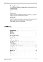
... 12 Troubleshooting 13 Appendix 14 Specifications 14 Dimensions 15 Block Diagram 16 CP2000-Owner's Manual ii Contents Package Contents The CP2000 package should contain the following items. Contact your Yamaha dealer if anything is missing. • CP2000 Power Amplifier • This manual Trademarks Yamaha is a trademark of their respective holders and are the property of...
... 12 Troubleshooting 13 Appendix 14 Specifications 14 Dimensions 15 Block Diagram 16 CP2000-Owner's Manual ii Contents Package Contents The CP2000 package should contain the following items. Contact your Yamaha dealer if anything is missing. • CP2000 Power Amplifier • This manual Trademarks Yamaha is a trademark of their respective holders and are the property of...
Owner's Manual
Page 5
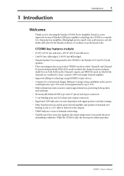
... fan stops for choosing the Yamaha CP2000 Power Amplifier. Based on each channel provide signal presence and clip warning. • Relay-based protection system protects both fed from the Channel L inputs, and BRIDGE mode in professional audio. CP2000-Owner's Manual 1 Introduction Introduction 1 Welcome Thank you for silent operation. CP2000 key features include •...
... fan stops for choosing the Yamaha CP2000 Power Amplifier. Based on each channel provide signal presence and clip warning. • Relay-based protection system protects both fed from the Channel L inputs, and BRIDGE mode in professional audio. CP2000-Owner's Manual 1 Introduction Introduction 1 Welcome Thank you for silent operation. CP2000 key features include •...
Owner's Manual
Page 6
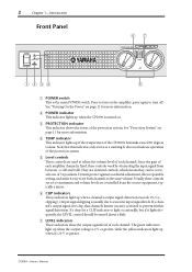
...of each amplifier channel is the main POWER switch. G LEVEL indicators These indicators show the output signal level of the CP2000's heatsinks exceed 85 degrees Celsius. 2 Chapter 1-Introduction Front Panel POWER TEMP PROTECTION POWER ON OFF 67 POWER AMPLIFIER 20 15 L... amplifier; Press to prevent further signal distortion. C PROTECTION indicator This indicator shows the status of the protection system. CP2000-Owner's Manual If a channel's output signal does clip, that this indicator only serves as a warning. It does not indicate operation of ...
...of each amplifier channel is the main POWER switch. G LEVEL indicators These indicators show the output signal level of the CP2000's heatsinks exceed 85 degrees Celsius. 2 Chapter 1-Introduction Front Panel POWER TEMP PROTECTION POWER ON OFF 67 POWER AMPLIFIER 20 15 L... amplifier; Press to prevent further signal distortion. C PROTECTION indicator This indicator shows the status of the protection system. CP2000-Owner's Manual If a channel's output signal does clip, that this indicator only serves as a warning. It does not indicate operation of ...
Owner's Manual
Page 7
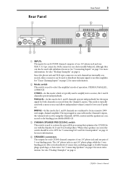
...more information. B Mode switch This switch is typically used to activate the special EQ processing that optimizes the CP2000 for use with unbalanced sources. CP2000-Owner's Manual The input signal is used with a mono source and allows independent volume control of two sets of speakers.... BRIDGE. D SPEAKERS connectors The outputs for both channels is sourced from the Channel L inputs, the volume level is typically used with the Yamaha S115 and S112 loudspeakers. See also "Hookup Examples" on page 4. See also "Hookup Examples" on page 4. STEREO-In this mode, ...
...more information. B Mode switch This switch is typically used to activate the special EQ processing that optimizes the CP2000 for use with unbalanced sources. CP2000-Owner's Manual The input signal is used with a mono source and allows independent volume control of two sets of speakers.... BRIDGE. D SPEAKERS connectors The outputs for both channels is sourced from the Channel L inputs, the volume level is typically used with the Yamaha S115 and S112 loudspeakers. See also "Hookup Examples" on page 4. See also "Hookup Examples" on page 4. STEREO-In this mode, ...
Owner's Manual
Page 8
...E GND terminal For safety reasons it is connected is grounded, then the CP2000 will be used to which it 's important that the CP2000 is grounded. If hum or noise occurs, try to eliminate it by... connecting this ground terminal. STEREO BRIDGE PARALLEL CHANNEL R 2 1 3 INPUT STEREO BRIDGE PARALLEL OFF ON CHANNEL L (BRIDGE) NEUTRIK 2 1 3 YAMAHA SPEAKER PROCESSING 2 1 ... following hookup example shows how the CP2000 can be made to this terminal to the 1/4" phone jacks and 5-way binding posts...
...E GND terminal For safety reasons it is connected is grounded, then the CP2000 will be used to which it 's important that the CP2000 is grounded. If hum or noise occurs, try to eliminate it by... connecting this ground terminal. STEREO BRIDGE PARALLEL CHANNEL R 2 1 3 INPUT STEREO BRIDGE PARALLEL OFF ON CHANNEL L (BRIDGE) NEUTRIK 2 1 3 YAMAHA SPEAKER PROCESSING 2 1 ... following hookup example shows how the CP2000 can be made to this terminal to the 1/4" phone jacks and 5-way binding posts...
Owner's Manual
Page 9
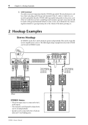
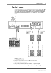
... the input signal for both channels is typically used in PARALLEL mode. CP2000-Owner's Manual This mode is sourced from the Channel L inputs. STEREO BRIDGE PARALLEL CHANNEL R 2 1 3 INPUT STEREO BRIDGE PARALLEL OFF ON CHANNEL L (BRIDGE) NEUTRIK 2 1 3 YAMAHA SPEAKER PROCESSING MONO OUT 2 1 1 2 CHANNEL R (-) BRIDGE (+)...; The input source must be connected to the 1/4" phone jacks and 5-way binding posts. The following hookup example shows how the CP2000 can be connected to the Channel L inputs. • The Channel R inputs are inactive. • The Channel L and Channel...
... the input signal for both channels is typically used in PARALLEL mode. CP2000-Owner's Manual This mode is sourced from the Channel L inputs. STEREO BRIDGE PARALLEL CHANNEL R 2 1 3 INPUT STEREO BRIDGE PARALLEL OFF ON CHANNEL L (BRIDGE) NEUTRIK 2 1 3 YAMAHA SPEAKER PROCESSING MONO OUT 2 1 1 2 CHANNEL R (-) BRIDGE (+)...; The input source must be connected to the 1/4" phone jacks and 5-way binding posts. The following hookup example shows how the CP2000 can be connected to the Channel L inputs. • The Channel R inputs are inactive. • The Channel L and Channel...
Owner's Manual
Page 10
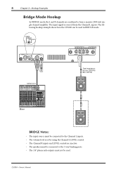
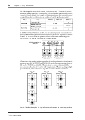
... be connected to form a massive 2000 watt single-channel amplifier. STEREO BRIDGE PARALLEL CHANNEL R 2 1 3 INPUT STEREO BRIDGE PARALLEL OFF ON CHANNEL L (BRIDGE) NEUTRIK 2 1 3 YAMAHA SPEAKER PROCESSING 2 1 1 2 CHANNEL R (-) BRIDGE (+) SPEAKERS CHANNEL L Total impedance: 4Ω min (2000 W) 8Ω (1300 W) MONO OUT Mixer BRIDGE Notes: • The input source must not be... Channel L LEVEL control. • The Channel R inputs and LEVEL control are combined to the 5-way binding posts. • The 1/4" phone jack outputs must be used . CP2000-Owner's Manual
... be connected to form a massive 2000 watt single-channel amplifier. STEREO BRIDGE PARALLEL CHANNEL R 2 1 3 INPUT STEREO BRIDGE PARALLEL OFF ON CHANNEL L (BRIDGE) NEUTRIK 2 1 3 YAMAHA SPEAKER PROCESSING 2 1 1 2 CHANNEL R (-) BRIDGE (+) SPEAKERS CHANNEL L Total impedance: 4Ω min (2000 W) 8Ω (1300 W) MONO OUT Mixer BRIDGE Notes: • The input source must not be... Channel L LEVEL control. • The Channel R inputs and LEVEL control are combined to the 5-way binding posts. • The 1/4" phone jack outputs must be used . CP2000-Owner's Manual
Owner's Manual
Page 11
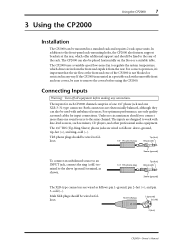
... 3 (cold) 2 (hot) CP2000-Owner's Manual For correct operation, it from the rear. The inputs for input connections. For optimum performance, use only quality screened cables for each CP2000 channel comprise of one 1/4" phone jack and one sound source to the same channel. The CP2000 uses a variable-speed low-noise ... as follows: pin 1-ground, pin 2-hot (+), and pin 3-cold (-). Connecting Inputs Warning: Turn off all equipment before using the CP2000. If the CP2000 is not blocked or restricted in from the front and expels it 's important that the air flow at the rear, which ...
... 3 (cold) 2 (hot) CP2000-Owner's Manual For correct operation, it from the rear. The inputs for input connections. For optimum performance, use only quality screened cables for each CP2000 channel comprise of one 1/4" phone jack and one sound source to the same channel. The CP2000 uses a variable-speed low-noise ... as follows: pin 1-ground, pin 2-hot (+), and pin 3-cold (-). Connecting Inputs Warning: Turn off all equipment before using the CP2000. If the CP2000 is not blocked or restricted in from the front and expels it 's important that the air flow at the rear, which ...
Owner's Manual
Page 12
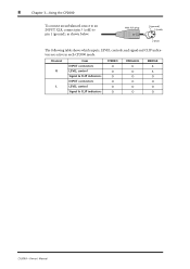
Channel R L Item INPUT connectors LEVEL control Signal & CLIP indicators INPUT connectors LEVEL control Signal & CLIP indicators STEREO O O O O O O PARALLEL X O O O O O BRIDGE X X O O O O CP2000-Owner's Manual Male XLR plug 1 (ground) 3 (cold) 2 (hot) The following table shows which inputs, LEVEL controls, and signal and CLIP indicators are active in each CP2000 mode. 8 Chapter 3-Using the CP2000 To connect an unbalanced source to an INPUT XLR, connect pin 3 (cold) to pin 1 (ground), as shown below.
Channel R L Item INPUT connectors LEVEL control Signal & CLIP indicators INPUT connectors LEVEL control Signal & CLIP indicators STEREO O O O O O O PARALLEL X O O O O O BRIDGE X X O O O O CP2000-Owner's Manual Male XLR plug 1 (ground) 3 (cold) 2 (hot) The following table shows which inputs, LEVEL controls, and signal and CLIP indicators are active in each CP2000 mode. 8 Chapter 3-Using the CP2000 To connect an unbalanced source to an INPUT XLR, connect pin 3 (cold) to pin 1 (ground), as shown below.
Owner's Manual
Page 13
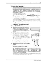
Caution for each CP2000 channel comprise of one 1/4" phone jack and one pair of the bare wires are splayed in such a way that the connection can be connected to ... none of 5-way binding posts. For optimum performance, use leads or a cord that have been manufactured in the posts, and then tighten the binding posts. CP2000-Owner's Manual The 1/4" phone jacks accept 1/4" phone plugs, while the 5-way binding posts offer several methods of insulation, unscrew the binding posts, and insert the bare...
Caution for each CP2000 channel comprise of one 1/4" phone jack and one pair of the bare wires are splayed in such a way that the connection can be connected to ... none of 5-way binding posts. For optimum performance, use leads or a cord that have been manufactured in the posts, and then tighten the binding posts. CP2000-Owner's Manual The 1/4" phone jacks accept 1/4" phone plugs, while the 5-way binding posts offer several methods of insulation, unscrew the binding posts, and insert the bare...
Owner's Manual
Page 14
...cabinets, make sure the total impedance is reduced, as the total impedance is 2Ω, and for more information on connecting speakers. CP2000-Owner's Manual When speakers are connected in parallel, the impedance is not less than the minimum. Mode Channel R Channel L Item Phone jack ... and PARALLEL modes, the minimum impedance is not less than the minimum specified. In BRIDGE mode, the speakers must be connected to each CP2000 mode and the minimum speaker impedance. STEREO and PARALLEL mode only 2 1 1 2 CHANNEL R (-) BRIDGE (+) SPEAKERS CHANNEL L 4Ω min ...
...cabinets, make sure the total impedance is reduced, as the total impedance is 2Ω, and for more information on connecting speakers. CP2000-Owner's Manual When speakers are connected in parallel, the impedance is not less than the minimum. Mode Channel R Channel L Item Phone jack ... and PARALLEL modes, the minimum impedance is not less than the minimum specified. In BRIDGE mode, the speakers must be connected to each CP2000 mode and the minimum speaker impedance. STEREO and PARALLEL mode only 2 1 1 2 CHANNEL R (-) BRIDGE (+) SPEAKERS CHANNEL L 4Ω min ...
Owner's Manual
Page 15
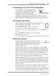
...turning off your equipment)-sound sources, mixer, CP2000. 1 Press the [POWER] switch to OFF. Heatsink overheating is set to abnormal operating conditions. Another layer of time, the thermostatic cutout CP2000-Owner's Manual Yamaha loudspeakers should be connected just like any other... speakers, make sure the YAMAHA SPEAKER PROCESSING switch is typically caused by inadequate ventilation and it's important ...
...turning off your equipment)-sound sources, mixer, CP2000. 1 Press the [POWER] switch to OFF. Heatsink overheating is set to abnormal operating conditions. Another layer of time, the thermostatic cutout CP2000-Owner's Manual Yamaha loudspeakers should be connected just like any other... speakers, make sure the YAMAHA SPEAKER PROCESSING switch is typically caused by inadequate ventilation and it's important ...
Owner's Manual
Page 16
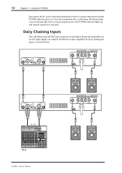
... inputs, as shown below. CHANNEL R 2 1 3 INPUT STEREO BRIDGE PARALLEL OFF ON CHANNEL L (BRIDGE) NEUTRIK 2 1 3 YAMAHA SPEAKER PROCESSING 2 1 1 2 CHANNEL R (-) BRIDGE (+) SPEAKERS CHANNEL L CHANNEL R 2 1 3 INPUT STEREO BRIDGE PARALLEL OFF ON CHANNEL L (BRIDGE) NEUTRIK 2 1 3 YAMAHA SPEAKER PROCESSING ST OUT Mixer CP2000-Owner's Manual 2 1 1 2 CHANNEL R (-) BRIDGE (+) SPEAKERS CHANNEL L Once the transformer has cooled down, the thermostatic cutout automatically...
... inputs, as shown below. CHANNEL R 2 1 3 INPUT STEREO BRIDGE PARALLEL OFF ON CHANNEL L (BRIDGE) NEUTRIK 2 1 3 YAMAHA SPEAKER PROCESSING 2 1 1 2 CHANNEL R (-) BRIDGE (+) SPEAKERS CHANNEL L CHANNEL R 2 1 3 INPUT STEREO BRIDGE PARALLEL OFF ON CHANNEL L (BRIDGE) NEUTRIK 2 1 3 YAMAHA SPEAKER PROCESSING ST OUT Mixer CP2000-Owner's Manual 2 1 1 2 CHANNEL R (-) BRIDGE (+) SPEAKERS CHANNEL L Once the transformer has cooled down, the thermostatic cutout automatically...
Owner's Manual
Page 17
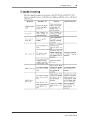
The heatsink temperature has exceeded 90˚C. Check the input connections and LEVEL control settings. The limiter circuit prevents further clipping distortion. Contact your Yamaha dealer or service center. The protection circuit activates, opening the output relay and disconnecting the speakers. Symptom POWER indicator not lit No sound Stereo sources ... circuit activates. A DC offset of the speaker connections and correct if necessary. There is too high. Make sure that 2Ω (STEREO/PARALLEL) or 4Ω (BRIDGE). - - - CP2000-Owner's Manual
The heatsink temperature has exceeded 90˚C. Check the input connections and LEVEL control settings. The limiter circuit prevents further clipping distortion. Contact your Yamaha dealer or service center. The protection circuit activates, opening the output relay and disconnecting the speakers. Symptom POWER indicator not lit No sound Stereo sources ... circuit activates. A DC offset of the speaker connections and correct if necessary. There is too high. Make sure that 2Ω (STEREO/PARALLEL) or 4Ω (BRIDGE). - - - CP2000-Owner's Manual
Owner's Manual
Page 18
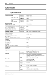
... +4 dB 33.8 dB 30 kΩ (balanced), 15 kΩ (unbalanced) POWER switch (push on/push off) LEVEL attenuator (31 position) x2 Mode switch (STEREO/BRIDGE/PARALLEL) YAMAHA SPEAKER PROCESSING switch (ON/OFF) XLR-3-31 type (balanced) L+R 1/4" phone jack (balanced) L+R 1/4" phone jack L+R 5-way binding post x1 x1 (green) x1 (red) x1 (red) heatsink...
... +4 dB 33.8 dB 30 kΩ (balanced), 15 kΩ (unbalanced) POWER switch (push on/push off) LEVEL attenuator (31 position) x2 Mode switch (STEREO/BRIDGE/PARALLEL) YAMAHA SPEAKER PROCESSING switch (ON/OFF) XLR-3-31 type (balanced) L+R 1/4" phone jack (balanced) L+R 1/4" phone jack L+R 5-way binding post x1 x1 (green) x1 (red) x1 (red) heatsink...
Owner's Manual
Page 19
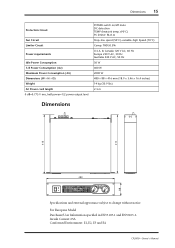
Inrush Current: 65A Conformed Environment: E1, E2, E3 and E4 CP2000-Owner's Manual Dimensions 15 Protection Circuit Fan Circuit Limiter Circuit Power requirements Idle Power Consumption 1/8 Power Consumption (4Ω) Maximum Power Consumption (4Ω) Dimensions (W × H × D) Weight AC ...
Inrush Current: 65A Conformed Environment: E1, E2, E3 and E4 CP2000-Owner's Manual Dimensions 15 Protection Circuit Fan Circuit Limiter Circuit Power requirements Idle Power Consumption 1/8 Power Consumption (4Ω) Maximum Power Consumption (4Ω) Dimensions (W × H × D) Weight AC ...


