
Owner's Manual
Page 1
E POWER AMPLIFIER Owner's Manual POWER TEMP PROTECTION POWER ON OFF POWER AMPLIFIER 20 15 L CLIP R 20 15 25 10 25 10 30 LEVEL 30 6 6 40 3 40 3 0 L -dB 0 R Keep This Manual For Future Reference.
E POWER AMPLIFIER Owner's Manual POWER TEMP PROTECTION POWER ON OFF POWER AMPLIFIER 20 15 L CLIP R 20 15 25 10 25 10 30 LEVEL 30 6 6 40 3 40 3 0 L -dB 0 R Keep This Manual For Future Reference.
Owner's Manual
Page 6
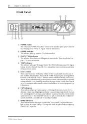
... clipping). Note that channel's limiter circuit is usually due to excessive input signal levels. F CLIP indicators These indicators light up when the CP2000 is turned on the amplifier; See "Protection System" on page 11 for more information. E Level controls These controls are used ... the status of each amplifier channel is the main POWER switch. 2 Chapter 1-Introduction Front Panel POWER TEMP PROTECTION POWER ON OFF 67 POWER AMPLIFIER 20 15 L CLIP R 20 15 25 10 25 10 30 LEVEL 30 6 6 40 3 40 3 0 L -dB 0 R 1 234 5 A POWER switch ...
... clipping). Note that channel's limiter circuit is usually due to excessive input signal levels. F CLIP indicators These indicators light up when the CP2000 is turned on the amplifier; See "Protection System" on page 11 for more information. E Level controls These controls are used ... the status of each amplifier channel is the main POWER switch. 2 Chapter 1-Introduction Front Panel POWER TEMP PROTECTION POWER ON OFF 67 POWER AMPLIFIER 20 15 L CLIP R 20 15 25 10 25 10 30 LEVEL 30 6 6 40 3 40 3 0 L -dB 0 R 1 234 5 A POWER switch ...
Owner's Manual
Page 7
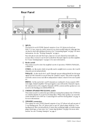
... using the Channel L LEVEL control, and the speakers are connected to activate the special EQ processing that optimizes the CP2000 for use with the Yamaha S115 and S112 loudspeakers. See "Connecting S115 and S112 loudspeakers" on each channel are used to the binding posts labelled...Channel L inputs, the volume level is used , this mode, the L and R channels are electronically balanced, although they can be used to amplify stereo sources, the L and R channels operate independently. D SPEAKERS connectors The outputs for both channels is typically used with a mono source and ...
... using the Channel L LEVEL control, and the speakers are connected to activate the special EQ processing that optimizes the CP2000 for use with the Yamaha S115 and S112 loudspeakers. See "Connecting S115 and S112 loudspeakers" on each channel are used to the binding posts labelled...Channel L inputs, the volume level is used , this mode, the L and R channels are electronically balanced, although they can be used to amplify stereo sources, the L and R channels operate independently. D SPEAKERS connectors The outputs for both channels is typically used with a mono source and ...
Owner's Manual
Page 8
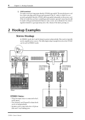
... a good ground point or the chassis of the AC outlet to amplify stereo sources. This mode is typically used in STEREO mode. 4 Chapter... channels operate independently. STEREO BRIDGE PARALLEL CHANNEL R 2 1 3 INPUT STEREO BRIDGE PARALLEL OFF ON CHANNEL L (BRIDGE) NEUTRIK 2 1 3 YAMAHA SPEAKER PROCESSING 2 1 1 2 CHANNEL R (-) BRIDGE (+) SPEAKERS CHANNEL L or ST OUT Total impedance: 2Ω min (1000 W) ...CP2000-Owner's Manual The following hookup example shows how the CP2000 can be connected to eliminate it 's important that the CP2000 is grounded, then the CP2000...
... a good ground point or the chassis of the AC outlet to amplify stereo sources. This mode is typically used in STEREO mode. 4 Chapter... channels operate independently. STEREO BRIDGE PARALLEL CHANNEL R 2 1 3 INPUT STEREO BRIDGE PARALLEL OFF ON CHANNEL L (BRIDGE) NEUTRIK 2 1 3 YAMAHA SPEAKER PROCESSING 2 1 1 2 CHANNEL R (-) BRIDGE (+) SPEAKERS CHANNEL L or ST OUT Total impedance: 2Ω min (1000 W) ...CP2000-Owner's Manual The following hookup example shows how the CP2000 can be connected to eliminate it 's important that the CP2000 is grounded, then the CP2000...

