Troubleshooting Guide
Page 23
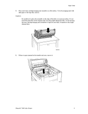
Do not touch the green film on the imaging units since this might damage the film. If there is paper jammed in . Paper Jams 3. Cover the imaging units with dark paper or the bags they came in the transfer unit area, remove it. 7300-08 Phaser® 7300 Color Printer 9 Place each toner cartridge/imaging unit assembly on the edge of the table or an uneven surface. Avoid exposing the toner cartridge/imaging unit assemblies to place the assembly on a flat surface. Caution Be careful not to light for more than 10 minutes as this might damage them. 7300-06 4.
Do not touch the green film on the imaging units since this might damage the film. If there is paper jammed in . Paper Jams 3. Cover the imaging units with dark paper or the bags they came in the transfer unit area, remove it. 7300-08 Phaser® 7300 Color Printer 9 Place each toner cartridge/imaging unit assembly on the edge of the table or an uneven surface. Avoid exposing the toner cartridge/imaging unit assemblies to place the assembly on a flat surface. Caution Be careful not to light for more than 10 minutes as this might damage them. 7300-06 4.
Troubleshooting Guide
Page 27
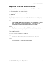
.... Caution Do not use detergents or solvents when cleaning the printer. All Rights Reserved. 13 Phaser® 7300 Color Printer Regular Printer Maintenance Your printer needs little maintenance other than periodic cleaning of life or replace...Transfer unit Fuser Clean the LED bars every time you replace a toner cartridge. Do not place the printer near end of direct sunlight. Cleaning the printer You can clean the outside of the printer. Note Turn the printer off before cleaning the external surfaces at the rear of the printer with a damp cloth. Copyright © 2002 Xerox...
.... Caution Do not use detergents or solvents when cleaning the printer. All Rights Reserved. 13 Phaser® 7300 Color Printer Regular Printer Maintenance Your printer needs little maintenance other than periodic cleaning of life or replace...Transfer unit Fuser Clean the LED bars every time you replace a toner cartridge. Do not place the printer near end of direct sunlight. Cleaning the printer You can clean the outside of the printer. Note Turn the printer off before cleaning the external surfaces at the rear of the printer with a damp cloth. Copyright © 2002 Xerox...
Troubleshooting Guide
Page 36
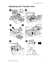
Replacing the Transfer Unit Replacing the Transfer Unit 00:10 1 2 2 1 00:10 3 1 2 Phaser® 7300 Color Printer 22
Replacing the Transfer Unit Replacing the Transfer Unit 00:10 1 2 2 1 00:10 3 1 2 Phaser® 7300 Color Printer 22

Troubleshooting Guide
Page 37
Replacing the Transfer Unit Phaser® 7300 Color Printer 23
Replacing the Transfer Unit Phaser® 7300 Color Printer 23
Service Manual
Page 38
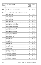
... Replace Magenta Toner Cartridge 66 Replace Yellow Toner Cartridge 67 Replace Black Toner Cartridge 68 Replace Cyan Imaging Unit 69 Replace Magenta Imaging Unit 70 Replace Yellow Imaging Unit 71 Replace Black Imaging Unit 72 Replace Transfer Unit 73 Close Right Door A 74 Close Right Door B 75 Close Right Door C 76 Close Right Door D 77 Close... 2 - 47 2 - 47 2 - 53 2 - 53 2 - 53 2 - 53 2 - 52 2 - 52 2 - 52 2 - 52 2 - 55 2 - 49 2 - 49 2 - 49 2 - 49 2 - 49 2 - 49 2 - 48 2 - 50 2 - 44 2 - 44 2 - 44 2 - 44 2 - 44 2-22 Phaser 7300 Color Printer Service Manual
... Replace Magenta Toner Cartridge 66 Replace Yellow Toner Cartridge 67 Replace Black Toner Cartridge 68 Replace Cyan Imaging Unit 69 Replace Magenta Imaging Unit 70 Replace Yellow Imaging Unit 71 Replace Black Imaging Unit 72 Replace Transfer Unit 73 Close Right Door A 74 Close Right Door B 75 Close Right Door C 76 Close Right Door D 77 Close... 2 - 47 2 - 47 2 - 53 2 - 53 2 - 53 2 - 53 2 - 52 2 - 52 2 - 52 2 - 52 2 - 55 2 - 49 2 - 49 2 - 49 2 - 49 2 - 49 2 - 49 2 - 48 2 - 50 2 - 44 2 - 44 2 - 44 2 - 44 2 - 44 2-22 Phaser 7300 Color Printer Service Manual
Service Manual
Page 46
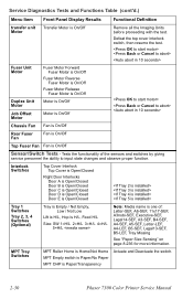
...more information. Service Diagnostics Tests and Functions Table (cont'd.) Menu Item Front Panel Display Results Functional Definition transfer unit Transfer Motor is On/Off Motor Fuser Unit Motor Duplex Unit Motor Job Offset Motor Fuser Motor Forward Fuser Motor is On/Off Fuser Motor Reverse Fuser Motor is ...On/Off Fuser Motor Release Fuser Motor is On/Off Motor is On/Off Motor is Paper/Transparency Actuate and Deactuate the switch. 2-30 Phaser 7300 Color Printer...
...more information. Service Diagnostics Tests and Functions Table (cont'd.) Menu Item Front Panel Display Results Functional Definition transfer unit Transfer Motor is On/Off Motor Fuser Unit Motor Duplex Unit Motor Job Offset Motor Fuser Motor Forward Fuser Motor is On/Off Fuser Motor Reverse Fuser Motor is ...On/Off Fuser Motor Release Fuser Motor is On/Off Motor is On/Off Motor is Paper/Transparency Actuate and Deactuate the switch. 2-30 Phaser 7300 Color Printer...
Service Manual
Page 52
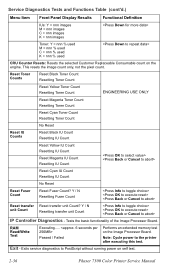
Y / N Resetting Fuser Count Reset transfer Reset transfer unit Count? Passed / Failed Performs an extended memory test on the engine. Service Diagnostics Tests and Functions Table (cont'd.) Menu Item Front...Read/Write Test Executing..... Note: Cycle power to PostScript without running power on self test. 2-36 Phaser 7300 Color Printer Service Manual Y / N unit Count Resetting transfer unit Count IP Controller Diagnostics - Exits service diagnostics to the printer after executing this test. This resets the image count only, not the pixel count. Tests the ...
Y / N Resetting Fuser Count Reset transfer Reset transfer unit Count? Passed / Failed Performs an extended memory test on the engine. Service Diagnostics Tests and Functions Table (cont'd.) Menu Item Front...Read/Write Test Executing..... Note: Cycle power to PostScript without running power on self test. 2-36 Phaser 7300 Color Printer Service Manual Y / N unit Count Resetting transfer unit Count IP Controller Diagnostics - Exits service diagnostics to the printer after executing this test. This resets the image count only, not the pixel count. Tests the ...
Service Manual
Page 54
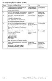
...[11]. for gaps between the Registration Rollers? 10 Use service diagnostics to test the following : solenoid. Main Feed Motor Transfer Unit Motor Registration Motor Registration Clutch Fuser Motor Replace the Engine Controller Board. sensor. Replace the following motors/clutches. Go to ... could Clean the sensor Go to step [9]. interfere with normal operation. and/or the problem motor/clutch. 2-38 Phaser 7300 Color Printer Service Manual Does the motor/clutch function correctly? 11 Inspect the wiring harness for each motor Replace the Replace the ...
...[11]. for gaps between the Registration Rollers? 10 Use service diagnostics to test the following : solenoid. Main Feed Motor Transfer Unit Motor Registration Motor Registration Clutch Fuser Motor Replace the Engine Controller Board. sensor. Replace the following motors/clutches. Go to ... could Clean the sensor Go to step [9]. interfere with normal operation. and/or the problem motor/clutch. 2-38 Phaser 7300 Color Printer Service Manual Does the motor/clutch function correctly? 11 Inspect the wiring harness for each motor Replace the Replace the ...
Service Manual
Page 74
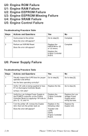
... step [2]. U6: Power Supply Failure Yes Go to the printer. pins 12, 13, and 14. 4 Turn the printer off, remove the Duplex Replace in the Unit, then turn the printer back on the Engine Controller Board. Replace the Duplex Unit. 2-58 Phaser 7300 Color Printer Service Manual Complete Troubleshooting Procedure Table Steps Actions and Questions Yes...Does the error still appear? operation and airflow. Are the fans operating correctly? 2 Verify +34 volts is supplying +34 volts to step [4]. F7 on . Transfer Unit LVPS HVPS Engine Controller Board. Go to step [2].
... step [2]. U6: Power Supply Failure Yes Go to the printer. pins 12, 13, and 14. 4 Turn the printer off, remove the Duplex Replace in the Unit, then turn the printer back on the Engine Controller Board. Replace the Duplex Unit. 2-58 Phaser 7300 Color Printer Service Manual Complete Troubleshooting Procedure Table Steps Actions and Questions Yes...Does the error still appear? operation and airflow. Are the fans operating correctly? 2 Verify +34 volts is supplying +34 volts to step [4]. F7 on . Transfer Unit LVPS HVPS Engine Controller Board. Go to step [2].
Service Manual
Page 78
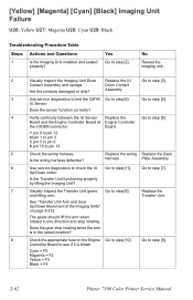
...Magenta = F2 Yellow = F3 Black = F4 2-62 Phaser 7300 Color Printer Service Manual Does the sensor function correctly? 4 Verify continuity between the IU Sensor Replace the Go to step [2]. No Reseat the imaging unit. 2 Visually inspect the Imaging Unit Drum Replace the IU Go to pin 13 5 Check the... 6 Use service diagnostics to check the IU Go to step [7]. Go to step [11]. Is the Transfer Unit functioning properly by lifting the Imaging Unit? 7 Visually inspect the Transfer Unit gears Go to see if it is in the raised position? 8 Check the appropriate fuse on page 8-...
...Magenta = F2 Yellow = F3 Black = F4 2-62 Phaser 7300 Color Printer Service Manual Does the sensor function correctly? 4 Verify continuity between the IU Sensor Replace the Go to step [2]. No Reseat the imaging unit. 2 Visually inspect the Imaging Unit Drum Replace the IU Go to pin 13 5 Check the... 6 Use service diagnostics to check the IU Go to step [7]. Go to step [11]. Is the Transfer Unit functioning properly by lifting the Imaging Unit? 7 Visually inspect the Transfer Unit gears Go to see if it is in the raised position? 8 Check the appropriate fuse on page 8-...
Service Manual
Page 96
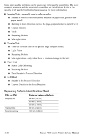
generally seen in only one color. ■ Streaks in Process Direction (in .) 3-80 Phaser 7300 Color Printer Service Manual only when there is obvious damage to paper travel ) ■ Banding in Scan Direction (across the page, perpendicular to the belt. ■ Fuser Unit ■ Hot or Cold Offsetting ■...LED Head ■ Streaks in the Process Direction ■ Uneven Density in the Scan Direction Repeating Defects Identification Chart FRU or CRC Imaging Unit Transfer Unit Fuser Assembly Distance between Defects 94 mm (3.70 in.) 50 mm (1.97 in.) 44 mm (1.73 in.) 58 mm (2.29 in.)...
generally seen in only one color. ■ Streaks in Process Direction (in .) 3-80 Phaser 7300 Color Printer Service Manual only when there is obvious damage to paper travel ) ■ Banding in Scan Direction (across the page, perpendicular to the belt. ■ Fuser Unit ■ Hot or Cold Offsetting ■...LED Head ■ Streaks in the Process Direction ■ Uneven Density in the Scan Direction Repeating Defects Identification Chart FRU or CRC Imaging Unit Transfer Unit Fuser Assembly Distance between Defects 94 mm (3.70 in.) 50 mm (1.97 in.) 44 mm (1.73 in.) 58 mm (2.29 in.)...
Service Manual
Page 98
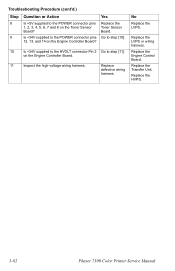
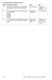
... the high-voltage wiring harness. Replace the LVPS or wiring harness. Replace the Transfer Unit. Yes Replace the Toner Sensor Board. Is +34V supplied to the POWER connector pins 1, 2, 3, 4, 5, 6, 7 and 8 on the Toner Sensor Board? Replace the HVPS. 3-82 Phaser 7300 Color Printer Service Manual Troubleshooting Procedure (cont'd.) Step 8 9 Question or Action Is +5V supplied...
... the high-voltage wiring harness. Replace the LVPS or wiring harness. Replace the Transfer Unit. Yes Replace the Toner Sensor Board. Is +34V supplied to the POWER connector pins 1, 2, 3, 4, 5, 6, 7 and 8 on the Toner Sensor Board? Replace the HVPS. 3-82 Phaser 7300 Color Printer Service Manual Troubleshooting Procedure (cont'd.) Step 8 9 Question or Action Is +5V supplied...
Service Manual
Page 100
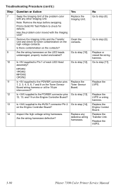
Imaging Unit. Board. Go to the POWER connector pins Replace the 1, 2, 3, 4, 5, 6, 7 and 8 on the LED heads undamaged, properly routed and seated? KPOW2 YPOW2 MPOW2 CPOW2 10 Is +5V supplied to step [10]. Replace in the following order: Transfer Unit LVPS 3-84 Phaser 7300 Color Printer Service Manual No Replace or reseat the wiring harness. Troubleshooting Procedure (cont'd.) Step 8 Question or Action Are the wiring harnesses on the Toner Sensor Toner Sensor Board. Yes Go to step [9]. 9 Is +5V supplied to Pin 1 of the problem LED Replace the Head assembly?
Imaging Unit. Board. Go to the POWER connector pins Replace the 1, 2, 3, 4, 5, 6, 7 and 8 on the LED heads undamaged, properly routed and seated? KPOW2 YPOW2 MPOW2 CPOW2 10 Is +5V supplied to step [10]. Replace in the following order: Transfer Unit LVPS 3-84 Phaser 7300 Color Printer Service Manual No Replace or reseat the wiring harness. Troubleshooting Procedure (cont'd.) Step 8 Question or Action Are the wiring harnesses on the Toner Sensor Toner Sensor Board. Yes Go to step [9]. 9 Is +5V supplied to Pin 1 of the problem LED Replace the Head assembly?

Service Manual
Page 102
Replace any defective wiring harnesses. on the Engine Controller Board? Replace the HVPS. 3-86 Phaser 7300 Color Printer Service Manual No Replace the LVPS or wiring harness. Yes Go to step [8]. 8 Is +34V supplied to the HVOLT connector Pin 2 Go to the POWER connector pins 12, 13, and 14 on the Engine Controller Board? 9 Inspect the high-voltage wiring harnesses. Replace the Engine Control Board. Troubleshooting Procedure (cont'd.) Step 7 Question or Action Is +34V supplied to step [9]. Replace the Transfer Unit.
Replace any defective wiring harnesses. on the Engine Controller Board? Replace the HVPS. 3-86 Phaser 7300 Color Printer Service Manual No Replace the LVPS or wiring harness. Yes Go to step [8]. 8 Is +34V supplied to the HVOLT connector Pin 2 Go to the POWER connector pins 12, 13, and 14 on the Engine Controller Board? 9 Inspect the high-voltage wiring harnesses. Replace the Engine Control Board. Troubleshooting Procedure (cont'd.) Step 7 Question or Action Is +34V supplied to step [9]. Replace the Transfer Unit.

Service Manual
Page 104
No Replace the Engine Control Board. defective wiring harnesses. Troubleshooting Procedure (cont'd.) Step 6 Question or Action Is +34V supplied to step [7]. 7 Inspect the high-voltage wiring harnesses. Replace any Are the wiring harnesses defective? Replace in the following order: Transfer Unit. Yes Go to the HVOLT connector Pin 2 on the Engine Controller Board.? HVPS. 3-88 Phaser 7300 Color Printer Service Manual
No Replace the Engine Control Board. defective wiring harnesses. Troubleshooting Procedure (cont'd.) Step 6 Question or Action Is +34V supplied to step [7]. 7 Inspect the high-voltage wiring harnesses. Replace any Are the wiring harnesses defective? Replace in the following order: Transfer Unit. Yes Go to the HVOLT connector Pin 2 on the Engine Controller Board.? HVPS. 3-88 Phaser 7300 Color Printer Service Manual
Service Manual
Page 106
... or wiring harness. Replace any other Imaging Unit. Replace the HVPS. 3-90 Phaser 7300 Color Printer Service Manual Go to step [8]. Print a Solid Fill Test Pattern to Pin 1 of the problem color with the Imaging Unit? Remove the Imaging Units and the Transfer Unit and check for defects. Yes Replace the Imaging Unit. Troubleshooting Procedure (cont'd.) Step 7 8 9 Question or Action...
... or wiring harness. Replace any other Imaging Unit. Replace the HVPS. 3-90 Phaser 7300 Color Printer Service Manual Go to step [8]. Print a Solid Fill Test Pattern to Pin 1 of the problem color with the Imaging Unit? Remove the Imaging Units and the Transfer Unit and check for defects. Yes Replace the Imaging Unit. Troubleshooting Procedure (cont'd.) Step 7 8 9 Question or Action...

Service Manual
Page 108
Remove the Imaging Units and the Transfer Unit and check for toner contamination on the high voltage contacts. Yes Clean the or replace the Drum Contacts. No Go to step [9]. Clean the contacts. Troubleshooting Procedure (cont'd.) Step 8 9 Question or Action Check the Imaging Unit contacts (3-pin contacts) and make sure they are in the following order: Transfer Unit HVPS 3-92 Phaser 7300 Color Printer Service Manual Replace in good working condition and not contaminated.
Remove the Imaging Units and the Transfer Unit and check for toner contamination on the high voltage contacts. Yes Clean the or replace the Drum Contacts. No Go to step [9]. Clean the contacts. Troubleshooting Procedure (cont'd.) Step 8 9 Question or Action Check the Imaging Unit contacts (3-pin contacts) and make sure they are in the following order: Transfer Unit HVPS 3-92 Phaser 7300 Color Printer Service Manual Replace in good working condition and not contaminated.

Service Manual
Page 134
... is set too high, media jams at registration rollers can occur. The Anvil "adjustment" is part of proper adjustment. 4-118 Phaser 7300 Color Printer Service Manual ATS Anvil Adjustment a. Automatic Thickness Sensor (ATS) Calibration Procedure The thickness of media being printed on can measure an incorrect... Right Cover - The Phaser 7300 printer has the ability to the fuser and fail the adjustment. 1. To adjust the anvil, loosen the screw and slide it up to reinstalling the Pickup Plate and Pickup Cover Assemblies. Note: Ensure the Transfer Unit Belt Entrance Sensor does not...
... is set too high, media jams at registration rollers can occur. The Anvil "adjustment" is part of proper adjustment. 4-118 Phaser 7300 Color Printer Service Manual ATS Anvil Adjustment a. Automatic Thickness Sensor (ATS) Calibration Procedure The thickness of media being printed on can measure an incorrect... Right Cover - The Phaser 7300 printer has the ability to the fuser and fail the adjustment. 1. To adjust the anvil, loosen the screw and slide it up to reinstalling the Pickup Plate and Pickup Cover Assemblies. Note: Ensure the Transfer Unit Belt Entrance Sensor does not...
Service Manual
Page 146
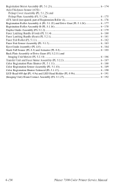
... Unit Motors (PL 5.2.13 6 - 186 Transfer Unit and Fuser Motor Assembly (PL 5.2.2 6 - 187 Color Registration Plate Shutter (PL 5.1.11 6 - 188 Color Registration Sensor Assembly (PL 5.1.10 6 - 189 Color Registration Shutter Solenoid (PL 5.1.13 6 - 190 LED Head 600 dpi (PL 4.9a) and LED Head Holder (PL 4.9b 6 - 191 (Imaging Unit) Drum Contact Assembly (PL 5.1.27 6 - 192 6-130 Phaser 7300 Color Printer...
... Unit Motors (PL 5.2.13 6 - 186 Transfer Unit and Fuser Motor Assembly (PL 5.2.2 6 - 187 Color Registration Plate Shutter (PL 5.1.11 6 - 188 Color Registration Sensor Assembly (PL 5.1.10 6 - 189 Color Registration Shutter Solenoid (PL 5.1.13 6 - 190 LED Head 600 dpi (PL 4.9a) and LED Head Holder (PL 4.9b 6 - 191 (Imaging Unit) Drum Contact Assembly (PL 5.1.27 6 - 192 6-130 Phaser 7300 Color Printer...

Service Manual
Page 172
...4. Remove the 5 G screws and the 3 B screw securing the Front Shield Plate and remove. Note: Label harnesses and ribbon cables to aid in place. 6-156 Phaser 7300 Color Printer Service Manual Remove the Rear Cover (see pg. 6-136). 5. Remove the Left Side Cover (see pg. 6-140). 9. Remove the 5 G and 2 B screws...the Electrical Card Cage and remove the plate. 10. Tape the open edge of the Electrical Card Cage. 12. Remove the Fuser and the Transfer Unit. 2. Remove the 4 G and 4 B screws securing the Top Shield Plate to keep the cables in reassembly. 11. Remove the Image Processor ...
...4. Remove the 5 G screws and the 3 B screw securing the Front Shield Plate and remove. Note: Label harnesses and ribbon cables to aid in place. 6-156 Phaser 7300 Color Printer Service Manual Remove the Rear Cover (see pg. 6-136). 5. Remove the Left Side Cover (see pg. 6-140). 9. Remove the 5 G and 2 B screws...the Electrical Card Cage and remove the plate. 10. Tape the open edge of the Electrical Card Cage. 12. Remove the Fuser and the Transfer Unit. 2. Remove the 4 G and 4 B screws securing the Top Shield Plate to keep the cables in reassembly. 11. Remove the Image Processor ...

