Quick Reference Guide
Page 2
This printing: January 2001 071-0725-00 To avoid personal injury, do so. PHASER® 2135 COLOR PRINTER Service Quick Reference Guide Warning The following servicing instructions are qualified to do not perform any servicing other than that contained in operating instructions unless you are for use by qualified service personnel only.
This printing: January 2001 071-0725-00 To avoid personal injury, do so. PHASER® 2135 COLOR PRINTER Service Quick Reference Guide Warning The following servicing instructions are qualified to do not perform any servicing other than that contained in operating instructions unless you are for use by qualified service personnel only.

Quick Reference Guide
Page 3
...Sun Microsystems®, and Sun Microsystems Computer Corporation® are registered trademarks of Sun Microsystems, Incorporated.Other marks are associated. Phaser®, PhaserShare®, ColorStix®, the TekColor® icon, Made For Each Other®, DocuPrint®, WorkSet®, Ethernet®,... the stylized X, and XEROX® are service marks of Xerox Corporation. FTP® Software is a registered trademark of Xerox Corporation. TE/sn Contents of this publication may not be reproduced in any form without ...
...Sun Microsystems®, and Sun Microsystems Computer Corporation® are registered trademarks of Sun Microsystems, Incorporated.Other marks are associated. Phaser®, PhaserShare®, ColorStix®, the TekColor® icon, Made For Each Other®, DocuPrint®, WorkSet®, Ethernet®,... the stylized X, and XEROX® are service marks of Xerox Corporation. FTP® Software is a registered trademark of Xerox Corporation. TE/sn Contents of this publication may not be reproduced in any form without ...
Quick Reference Guide
Page 6
Contents General Information 1 The Phaser 2135 Color Printer 2 Printer RAM and printer capabilities 4 CRC life counter behavior 4 Print engine assemblies 5 The image processor board 8 The control panel 9 On Line LED 9 ! Fault 9 Rear panel 10 Accessing special operating ... 17 Troubleshooting 29 Fault History Log 29 Power on self-diagnostic test 30 Print engine troubleshooting 31 Testing the print engine controller board 31 Verifying printer operation by using its self-test print 32 Verifying power supply operation 32 Measuring power supply voltages 32 Inspecting the low-voltage power supply fuse...
Contents General Information 1 The Phaser 2135 Color Printer 2 Printer RAM and printer capabilities 4 CRC life counter behavior 4 Print engine assemblies 5 The image processor board 8 The control panel 9 On Line LED 9 ! Fault 9 Rear panel 10 Accessing special operating ... 17 Troubleshooting 29 Fault History Log 29 Power on self-diagnostic test 30 Print engine troubleshooting 31 Testing the print engine controller board 31 Verifying printer operation by using its self-test print 32 Verifying power supply operation 32 Measuring power supply voltages 32 Inspecting the low-voltage power supply fuse...
Quick Reference Guide
Page 7
...installed 43 Imaging drum up/down error 43 Fan error 44 Fuser unit error 44 Other problems 45 The printer continuously displays "Booting" or "Initializing." 45 False "No toner cartridge installed" message 45 False "No...colors 56 Image is skewed on the paper 57 Image is not centered on the print 57 The print is wrinkled 57 Macintosh printing problems 58 Image never prints 58 Image is rotated 90 degrees 58 Image prints in black-and-white 58 Printer... isn't in the Chooser 59 Windows printing problems 59 Image never prints 59 vi Phaser 2135 Color Printer
...installed 43 Imaging drum up/down error 43 Fan error 44 Fuser unit error 44 Other problems 45 The printer continuously displays "Booting" or "Initializing." 45 False "No toner cartridge installed" message 45 False "No...colors 56 Image is skewed on the paper 57 Image is not centered on the print 57 The print is wrinkled 57 Macintosh printing problems 58 Image never prints 58 Image is rotated 90 degrees 58 Image prints in black-and-white 58 Printer... isn't in the Chooser 59 Windows printing problems 59 Image never prints 59 vi Phaser 2135 Color Printer

Quick Reference Guide
Page 9
... handle (front) 132 Fuser latching handle (rear) 134 Fuser exit roller 135 Exit sensor assembly 137 Eject guide assembly 138 Stack full sensor 139 viii Phaser 2135 Color Printer
... handle (front) 132 Fuser latching handle (rear) 134 Fuser exit roller 135 Exit sensor assembly 137 Eject guide assembly 138 Stack full sensor 139 viii Phaser 2135 Color Printer

Quick Reference Guide
Page 11
...The Phaser 2135 Color Printer with lower tray assembly and lower tray deck 1 Print engine circuit boards 5 Print engine sensor and switch locations 6 Print engine motors, clutches and solenoids 7 Features of the controller board 8 The control panel 9 The printer rear ... Removing the electrical card cage 99 Disconnecting the registration motor in-line connector (HOPFF) 100 Removing the printer unit chassis 101 Removing the top shield plate 103 Removing the left plate assembly 104 Removing the system ...main feeder assembly 118 Removing the multi-sheet bypass feeder 120 x Phaser 2135 Color Printer
...The Phaser 2135 Color Printer with lower tray assembly and lower tray deck 1 Print engine circuit boards 5 Print engine sensor and switch locations 6 Print engine motors, clutches and solenoids 7 Features of the controller board 8 The control panel 9 The printer rear ... Removing the electrical card cage 99 Disconnecting the registration motor in-line connector (HOPFF) 100 Removing the printer unit chassis 101 Removing the top shield plate 103 Removing the left plate assembly 104 Removing the system ...main feeder assembly 118 Removing the multi-sheet bypass feeder 120 x Phaser 2135 Color Printer
Quick Reference Guide
Page 13
... and top cover 154 FRU part list of the top cover inner frame 156 FRU part list of the printer chassis (1 of 2) 158 FRU of the printer chassis (2 of 2) 160 FRU of the paper tray and paper tray guides 162 Electrical components FRUs 164 FRUs... flag kit 170 Customer supplies and accessories 170 xii Phaser 2135 Color Printer Tables Entering special operating modes 11 Paper size detection 12 Physical dimensions 13 Printer clearances 13 Functional specifications 14 Electrical specifications 15 Environmental specifications 15 Printer fault messages 17 System controller board diagnostic error codes ...
... and top cover 154 FRU part list of the top cover inner frame 156 FRU part list of the printer chassis (1 of 2) 158 FRU of the printer chassis (2 of 2) 160 FRU of the paper tray and paper tray guides 162 Electrical components FRUs 164 FRUs... flag kit 170 Customer supplies and accessories 170 xii Phaser 2135 Color Printer Tables Entering special operating modes 11 Paper size detection 12 Physical dimensions 13 Printer clearances 13 Functional specifications 14 Electrical specifications 15 Environmental specifications 15 Printer fault messages 17 System controller board diagnostic error codes ...
Quick Reference Guide
Page 14
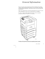
General Information This service guide contains information useful for troubleshooting, repairing, adjusting, and maintaining the Xerox Phaser® 2135 Color Printer. Topics such as printer theory of the product, Xerox recommends participation in Phaser 2135 printer service training. 0725-56 The Phaser 2135 Color Printer with lower tray assembly and lower tray deck Service Guide 1 This manual includes troubleshooting guides, adjustment procedures...
General Information This service guide contains information useful for troubleshooting, repairing, adjusting, and maintaining the Xerox Phaser® 2135 Color Printer. Topics such as printer theory of the product, Xerox recommends participation in Phaser 2135 printer service training. 0725-56 The Phaser 2135 Color Printer with lower tray assembly and lower tray deck Service Guide 1 This manual includes troubleshooting guides, adjustment procedures...

Quick Reference Guide
Page 15
...Page Preview" mode and a secure print job "password" mode. For 600 x 1200 dpi (enhanced) color printing, the printer prints color at 600 x 600 dpi. The Phaser 2135N prints at a color resolutions of RAM. The resolution supported is a function of memory, an auto-duplexer, an internal hard ...-sheet bypass feeder from which specialty media, cardstock and envelopes can be fed. 2 Phaser 2135 Color Printer Print speeds depend on the Phaser 2135N) allows the printer to 5 trays. The printer also features a built-in fonts. The auto-duplexer unit (optional on the chosen ...
...Page Preview" mode and a secure print job "password" mode. For 600 x 1200 dpi (enhanced) color printing, the printer prints color at 600 x 600 dpi. The Phaser 2135N prints at a color resolutions of RAM. The resolution supported is a function of memory, an auto-duplexer, an internal hard ...-sheet bypass feeder from which specialty media, cardstock and envelopes can be fed. 2 Phaser 2135 Color Printer Print speeds depend on the Phaser 2135N) allows the printer to 5 trays. The printer also features a built-in fonts. The auto-duplexer unit (optional on the chosen ...
Quick Reference Guide
Page 17
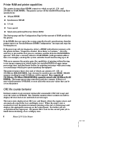
...defective RAM DIMM is reached for the current print job to use off-the-shelf RAM meeting these counters in the printer. The printer features three slots each of current page and displays the appropriate message on the control panel. Press Enter to store all...processing controller board also contains 16-kbytes of printing without having to finish before declaring a Low or Empty state. 4 Phaser 2135 Color Printer If the power-up at the end of which gives greater printing throughput). CRC life counter behavior Internal counters track customer replaceable ...
...defective RAM DIMM is reached for the current print job to use off-the-shelf RAM meeting these counters in the printer. The printer features three slots each of current page and displays the appropriate message on the control panel. Press Enter to store all...processing controller board also contains 16-kbytes of printing without having to finish before declaring a Low or Empty state. 4 Phaser 2135 Color Printer If the power-up at the end of which gives greater printing throughput). CRC life counter behavior Internal counters track customer replaceable ...
Quick Reference Guide
Page 19
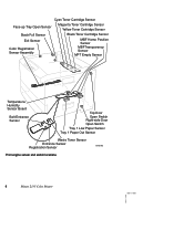
Cyan Toner Cartridge Sensor Face-up Tray Open Sensor Magenta Toner Cartridge Sensor Yellow Toner Cartridge Sensor Stack Full Sensor Black Toner Cartridge Sensor Exit Sensor Color Registration Sensor Assembly MBF Home Position Sensor MBFTransparency Sensor MPT Empty Sensor Temperature/ Humidity Sensor Board Belt Entrance Sensor Top Door Open Switch Right-side Door Open Switch Tray 1 Low Paper Sensor Tray 1 Paper Out Sensor Waste Toner Sensor Entrance Sensor Registration Sensor 0725-63 Print engine sensor and switch locations 6 Phaser 2135 Color Printer
Cyan Toner Cartridge Sensor Face-up Tray Open Sensor Magenta Toner Cartridge Sensor Yellow Toner Cartridge Sensor Stack Full Sensor Black Toner Cartridge Sensor Exit Sensor Color Registration Sensor Assembly MBF Home Position Sensor MBFTransparency Sensor MPT Empty Sensor Temperature/ Humidity Sensor Board Belt Entrance Sensor Top Door Open Switch Right-side Door Open Switch Tray 1 Low Paper Sensor Tray 1 Paper Out Sensor Waste Toner Sensor Entrance Sensor Registration Sensor 0725-63 Print engine sensor and switch locations 6 Phaser 2135 Color Printer
Quick Reference Guide
Page 21
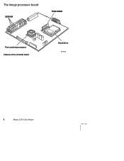
The image processor board SDRAM ROM DIMM Fan cooled processor Features of the controller board Hard drive 0728-05 8 Phaser 2135 Color Printer
The image processor board SDRAM ROM DIMM Fan cooled processor Features of the controller board Hard drive 0728-05 8 Phaser 2135 Color Printer
Quick Reference Guide
Page 23
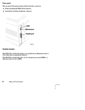
s Twisted Pair 10/100baseT Ethernet connector. LEDs Ethernet port Parallel port 0728-03 The printer rear panel The LED LNK is off when the card is set for 4 megabits-per-second (MBPS), on an Ethernet network, it blinks while data is set for 16 MBPS. 10 Phaser 2135 Color Printer Rear panel The rear panel of the printer features the host interface connectors: s Bi-directional parallel IEEE 1284-B connector. The LED SPD is off when the printer is not installed on when the card is transmitted to the host.
s Twisted Pair 10/100baseT Ethernet connector. LEDs Ethernet port Parallel port 0728-03 The printer rear panel The LED LNK is off when the card is set for 4 megabits-per-second (MBPS), on an Ethernet network, it blinks while data is set for 16 MBPS. 10 Phaser 2135 Color Printer Rear panel The rear panel of the printer features the host interface connectors: s Bi-directional parallel IEEE 1284-B connector. The LED SPD is off when the printer is not installed on when the card is transmitted to the host.
Quick Reference Guide
Page 25
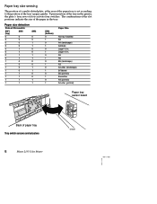
...of the slot positions indicate the size of paper tray Tray switch sensors and actuators 12 Phaser 2135 Color Printer 0725-67 A5 A6 B5 (landscape) A3 A/Letter (landscape) B/Tabloid B5 (portrait...) Executive A4 (portrait) A/Letter (portrait) Paper tray sensor board Back of the paper in the printer, the plate's four rows of the tray's paper guides. Legal 14 in . Paper size detection State of Microswitch SW1 (top) SW2 0 0 0 0 0 0 0 0 0 1 0 1 0 1 0 1 1 0 1 0 1 0 1 0 1...
...of the slot positions indicate the size of paper tray Tray switch sensors and actuators 12 Phaser 2135 Color Printer 0725-67 A5 A6 B5 (landscape) A3 A/Letter (landscape) B/Tabloid B5 (portrait...) Executive A4 (portrait) A/Letter (portrait) Paper tray sensor board Back of the paper in the printer, the plate's four rows of the tray's paper guides. Legal 14 in . Paper size detection State of Microswitch SW1 (top) SW2 0 0 0 0 0 0 0 0 0 1 0 1 0 1 0 1 1 0 1 0 1 0 1 0 1...
Quick Reference Guide
Page 27
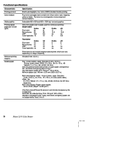
...17 in .), A6, JIS B5, US Folio, A5. Use only premium bond laser printer or copier paper, transparency film, card stock and glossy paper in Tray 1 Tray feed paper weight: 60 to 163 g/m2 (16 to 203 g/m2) Only Xerox-brand Phaser 35-series A- All sides 5 mm (0.2 in.), Tray: A-size (Letter), ... to 32 lb.) A6 paper, transparency film, heavy card stock, and glossy paper are not supported by Trays 2 thru 5 14 Phaser 2135 Color Printer and A4-size transparency film is a nonmagnetic, monocomponent contact medium. Functional specifications Characteristic Printing process...
...17 in .), A6, JIS B5, US Folio, A5. Use only premium bond laser printer or copier paper, transparency film, card stock and glossy paper in Tray 1 Tray feed paper weight: 60 to 163 g/m2 (16 to 203 g/m2) Only Xerox-brand Phaser 35-series A- All sides 5 mm (0.2 in.), Tray: A-size (Letter), ... to 32 lb.) A6 paper, transparency film, heavy card stock, and glossy paper are not supported by Trays 2 thru 5 14 Phaser 2135 Color Printer and A4-size transparency film is a nonmagnetic, monocomponent contact medium. Functional specifications Characteristic Printing process...
Quick Reference Guide
Page 29
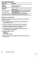
...Processing and Business Equipment. Standby: 45 dBa, Running: 54 dBa, Impulse: 57 dBa Regulatory specifications The printer is a recognized component in .) without impairment of Information Technology Equipment, Including Electrical Business Equipment. Environmental specifications ...with the following regulatory standards: s The packaged product meets ASTM D4169-93 and ASTM D4728-91 Transportation Standards. ICES 03 Class B 16 Phaser 2135 Color Printer s GS licensed IEC 950 (1991) Second Edition; s EN50022 (CISPR 22) Class B EN61000-3-2 EN61000-3-3 VCCI (CISPR 22) Class...
...Processing and Business Equipment. Standby: 45 dBa, Running: 54 dBa, Impulse: 57 dBa Regulatory specifications The printer is a recognized component in .) without impairment of Information Technology Equipment, Including Electrical Business Equipment. Environmental specifications ...with the following regulatory standards: s The packaged product meets ASTM D4169-93 and ASTM D4728-91 Transportation Standards. ICES 03 Class B 16 Phaser 2135 Color Printer s GS licensed IEC 950 (1991) Second Edition; s EN50022 (CISPR 22) Class B EN61000-3-2 EN61000-3-3 VCCI (CISPR 22) Class...
Quick Reference Guide
Page 31
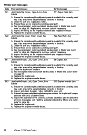
... Ensure the paper path leading to the duplex unit and the duplex unit's paper path are no obstructions in the currently used tray. Printer fault messages Code A11 A22 B8 B13 Front panel message Service message Jam Inside Top Cover, Open Cover, See Labels A11-Paper Feed... the motor or clutch if necessary. 5. Inspect and clean the eject rollers behind the fuser unit. 3. Replace the engine controller board. 18 Phaser 2135 Color Printer Clean the pick and registration rollers. 3. Jam Inside Duplex Unit, Open Cover, See Labels B8-Duplex Jam 1. Jam Inside Duplex Unit, Open...
... Ensure the paper path leading to the duplex unit and the duplex unit's paper path are no obstructions in the currently used tray. Printer fault messages Code A11 A22 B8 B13 Front panel message Service message Jam Inside Top Cover, Open Cover, See Labels A11-Paper Feed... the motor or clutch if necessary. 5. Inspect and clean the eject rollers behind the fuser unit. 3. Replace the engine controller board. 18 Phaser 2135 Color Printer Clean the pick and registration rollers. 3. Jam Inside Duplex Unit, Open Cover, See Labels B8-Duplex Jam 1. Jam Inside Duplex Unit, Open...
Quick Reference Guide
Page 33
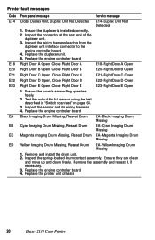
...Door E Open 1. Inspect the sensor and its wiring harness. 4. Remove the assembly and reseat it, if necessary. 3. Replace the printer unit chassis 20 Phaser 2135 Color Printer Inspect the wiring harness leading from the duplexer unit interface connector to the engine controller board. 4. Remove and install the drum unit. ...the test described in "Switch scan test" on page 63. 3. Replace the engine controller board. 4. Replace the duplexer unit. 5. Printer fault messages Code E14 E18 E20 E21 E22 E23 EA EB EC ED Front panel message Service message Close Duplex Unit, Duplex Unit Not...
...Door E Open 1. Inspect the sensor and its wiring harness. 4. Remove the assembly and reseat it, if necessary. 3. Replace the printer unit chassis 20 Phaser 2135 Color Printer Inspect the wiring harness leading from the duplexer unit interface connector to the engine controller board. 4. Remove and install the drum unit. ...the test described in "Switch scan test" on page 63. 3. Replace the engine controller board. 4. Replace the duplexer unit. 5. Printer fault messages Code E14 E18 E20 E21 E22 E23 EA EB EC ED Front panel message Service message Close Duplex Unit, Duplex Unit Not...

Quick Reference Guide
Page 35
... count initialization" on page 73. 3. Replace the drum unit. 4. Load Tray # 1 Size 2 Type 3 Load Tray #, Size Type 1. Replace the engine controller board. 22 Phaser 2135 Color Printer Install a new drum unit. 2. Ensure they are clean and move up and down freely. Load the requested size and type of three...). Printer fault messages Code J5 J6 J7 J8 J9 J10 J11 J12 L0 Front panel message Service message Replace Yellow Imaging Drum J5-Replace...
... count initialization" on page 73. 3. Replace the drum unit. 4. Load Tray # 1 Size 2 Type 3 Load Tray #, Size Type 1. Replace the engine controller board. 22 Phaser 2135 Color Printer Install a new drum unit. 2. Ensure they are clean and move up and down freely. Load the requested size and type of three...). Printer fault messages Code J5 J6 J7 J8 J9 J10 J11 J12 L0 Front panel message Service message Replace Yellow Imaging Drum J5-Replace...
Quick Reference Guide
Page 37
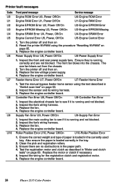
...Replace the fan. 4. Inspect the main cooling fan to see if it is running and not blocked. 2. Replace the fan. 4. Reset the printer NVRAM using the test described in "Switch scan test" on page 85. 3. Replace the low-voltage power supply. 4. Replace the engine controller ... in the currently used tray. Inspect the wiring for the registration clutch and registration motor. 6. Replace the engine controller board. 24 Phaser 2135 Color Printer Inspect the front and rear power supply fans. Test the manual bypass feeder home sensor using the procedure "Resetting NVRAM" on page 63...
...Replace the fan. 4. Inspect the main cooling fan to see if it is running and not blocked. 2. Replace the fan. 4. Reset the printer NVRAM using the test described in "Switch scan test" on page 85. 3. Replace the low-voltage power supply. 4. Replace the engine controller ... in the currently used tray. Inspect the wiring for the registration clutch and registration motor. 6. Replace the engine controller board. 24 Phaser 2135 Color Printer Inspect the front and rear power supply fans. Test the manual bypass feeder home sensor using the procedure "Resetting NVRAM" on page 63...


