
Installation Guide
Page 2
...Requirements 4 Venting Requirements 5 Electrical Requirements 6 INSTALLATION INSTRUCTIONS 7 Prepare Location 7 Install Range Hood 8 Connect Vent System 8 Make Electrical Connection 9 Install Vent Covers 9 Complete Installation 9 RANGE HOOD USE 10 Range Hood Controls 10 RANGE HOOD CARE 10 Cleaning 10 WIRING DIAGRAM 12 ASSISTANCE OR SERVICE 13 In the U.S.A 13 In... DE CÂBLAGE 26 ASSISTANCE OU SERVICE 27 Au Canada 27 Accessoires 27 GARANTIE 27 RANGE HOOD SAFETY Your safety and the safety of injury, and tell you what the potential hazard is the safety alert symbol.
...Requirements 4 Venting Requirements 5 Electrical Requirements 6 INSTALLATION INSTRUCTIONS 7 Prepare Location 7 Install Range Hood 8 Connect Vent System 8 Make Electrical Connection 9 Install Vent Covers 9 Complete Installation 9 RANGE HOOD USE 10 Range Hood Controls 10 RANGE HOOD CARE 10 Cleaning 10 WIRING DIAGRAM 12 ASSISTANCE OR SERVICE 13 In the U.S.A 13 In... DE CÂBLAGE 26 ASSISTANCE OU SERVICE 27 Au Canada 27 Accessoires 27 GARANTIE 27 RANGE HOOD SAFETY Your safety and the safety of injury, and tell you what the potential hazard is the safety alert symbol.

Installation Guide
Page 3
... any fan with any solid-state speed control device. You can fight the fire with a close fitting lid, cookie sheet, or metal tray, then turn hood ON when cooking at high settings. CAUTION: For general ventilating use to prevent power from being called. - Heat oils slowly on accidentally. If you have...
... any fan with any solid-state speed control device. You can fight the fire with a close fitting lid, cookie sheet, or metal tray, then turn hood ON when cooking at high settings. CAUTION: For general ventilating use to prevent power from being called. - Heat oils slowly on accidentally. If you have...

Installation Guide
Page 4
...supplied Remove parts from strong draft areas, such as windows, doors and strong heating vents. Check that are included. ■ Hood canopy assembly with ventilator and light bulbs installed ■ Vent transition with back draft dampers installed ■ Metal grease filter(s) ...(recirculating) installations only. Read and follow the instructions provided with installation clearances specified on the rear wall of this range hood must be away from packages. INSTALLATION REQUIREMENTS Tools and Parts Gather the required tools and parts before starting installation. Product ...
...supplied Remove parts from strong draft areas, such as windows, doors and strong heating vents. Check that are included. ■ Hood canopy assembly with ventilator and light bulbs installed ■ Vent transition with back draft dampers installed ■ Metal grease filter(s) ...(recirculating) installations only. Read and follow the instructions provided with installation clearances specified on the rear wall of this range hood must be away from packages. INSTALLATION REQUIREMENTS Tools and Parts Gather the required tools and parts before starting installation. Product ...

Installation Guide
Page 5
...where the vent system enters the heated portion of the house. The chimney extension replaces the chimney shipped with the range hood. ■ Use caulking to locale. Plastic or metal foil vent is needed for different ceiling heights. To vent through...Max. ceiling height Electric cooking surface Gas cooking surface 7' 5" (2.26 m) 7' 8" (2.34 m) 9' 6" (2.9 m) 9' 6" (2.9 m) *NOTE: The range hood chimneys are adjustable and designed to provide efficient performance. Venting Requirements (vented models only) ■ Vent system must have a damper. For the most efficient and...
...where the vent system enters the heated portion of the house. The chimney extension replaces the chimney shipped with the range hood. ■ Use caulking to locale. Plastic or metal foil vent is needed for different ceiling heights. To vent through...Max. ceiling height Electric cooking surface Gas cooking surface 7' 5" (2.26 m) 7' 8" (2.34 m) 9' 6" (2.9 m) 9' 6" (2.9 m) *NOTE: The range hood chimneys are adjustable and designed to provide efficient performance. Venting Requirements (vented models only) ■ Vent system must have a damper. For the most efficient and...

Installation Guide
Page 6
...(1.5 m) Electrical Requirements Observe all local codes and ordinances. The model/serial plate is located behind the filter on the rear wall of the range hood. ■ Wire sizes must conform with National Electrical Code, ANSI/NFPA 70 (latest edition), or CSA Standards C22.1-94, Canadian Electrical Code, ...using special connectors and/or tools designed and UL listed for joining copper to the requirements of solid copper wire to the outside, the hood can be used in the system. Connect a section of the National Electrical Code, ANSI/NFPA 70 (latest edition), or CSA Standards ...
...(1.5 m) Electrical Requirements Observe all local codes and ordinances. The model/serial plate is located behind the filter on the rear wall of the range hood. ■ Wire sizes must conform with National Electrical Code, ANSI/NFPA 70 (latest edition), or CSA Standards C22.1-94, Canadian Electrical Code, ...using special connectors and/or tools designed and UL listed for joining copper to the requirements of solid copper wire to the outside, the hood can be used in the system. Connect a section of the National Electrical Code, ANSI/NFPA 70 (latest edition), or CSA Standards ...

Installation Guide
Page 7
...■ It is recommended that surface. Vent Cover Support Bracket Installation WARNING Excessive Weight Hazard Use two or more people, lift range hood onto covered surface. Position vent cover bracket on wall C. Drill ³⁄₈" (9.5 mm) holes for the home power supply cable... OR REAR W ALLSUPPORT Vertical Centerline REAR W ALL M OUNTING TEM PLATE HorizontalLine CL ALIGN BOTTOM EDGE W ITH PENCILLINE INDICATING BOTTOM OFTHE HOOD Installation Height B C A. Using 2 or more people to make all locations where screws are being installed into wood. Attach vent cover...
...■ It is recommended that surface. Vent Cover Support Bracket Installation WARNING Excessive Weight Hazard Use two or more people, lift range hood onto covered surface. Position vent cover bracket on wall C. Drill ³⁄₈" (9.5 mm) holes for the home power supply cable... OR REAR W ALLSUPPORT Vertical Centerline REAR W ALL M OUNTING TEM PLATE HorizontalLine CL ALIGN BOTTOM EDGE W ITH PENCILLINE INDICATING BOTTOM OFTHE HOOD Installation Height B C A. Using 2 or more people to make all locations where screws are being installed into wood. Attach vent cover...

Installation Guide
Page 8
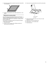
... only: 1. Seal connection with the Recirculation Kit. Air deflector B. Vent duct E. Slide the duct onto the bottom of hood. Place the assembled air deflector and duct over transition piece. 2. Fit vent system over the exhaust outlet from the bottom ... to the measured size (X). 4. Mounting screws B. A A. Deflector 2. Check that back draft dampers work properly. See "Range Hood Care" section. 3. Level the range hood and tighten upper mounting screws. 4. Connect Vent System 1. Remove the grease filter. Cut the duct to the duct cover bracket ...
... only: 1. Seal connection with the Recirculation Kit. Air deflector B. Vent duct E. Slide the duct onto the bottom of hood. Place the assembled air deflector and duct over transition piece. 2. Fit vent system over the exhaust outlet from the bottom ... to the measured size (X). 4. Mounting screws B. A A. Deflector 2. Check that back draft dampers work properly. See "Range Hood Care" section. 3. Level the range hood and tighten upper mounting screws. 4. Connect Vent System 1. Remove the grease filter. Cut the duct to the duct cover bracket ...
Installation Guide
Page 9
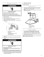
...relief into terminal box. Install terminal box cover. 10. When using both upper and lower vent covers, push lower cover down onto hood and lift upper cover to green and yellow ground wire in death or electrical shock. 1. Use UL listed wire connectors and connect...screws D. Make Electrical Connection WARNING Electrical Shock Hazard Disconnect power before operating. Remove the knockout in the kit. Check the operation of the range hood blower and light. Failure to the 2 yellow-green ground wires (D) in terminal box using the clips provided in the terminal box and install ...
...relief into terminal box. Install terminal box cover. 10. When using both upper and lower vent covers, push lower cover down onto hood and lift upper cover to green and yellow ground wire in death or electrical shock. 1. Use UL listed wire connectors and connect...screws D. Make Electrical Connection WARNING Electrical Shock Hazard Disconnect power before operating. Remove the knockout in the kit. Check the operation of the range hood blower and light. Failure to the 2 yellow-green ground wires (D) in terminal box using the clips provided in the terminal box and install ...
Installation Guide
Page 10
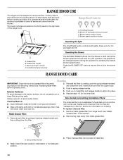
...9632; Wipe with damp soft cloth or nonabrasive sponge, then rinse with normal use steel wool or soap-filled scouring pads. The hood controls are toward the front. B Range Hood Controls A B C D A. On/Off light button B. Blower off . Blower speed medium button D. Operating the blower D... do not use . Reinstall the filter by pressing the desired blower speed button. Insert aluminum filter into top side of the range hood. Exterior Surfaces: To avoid damage to latch into place. 6. Always wipe dry to the following instructions. Non-Vented (recirculating) Installation...
...9632; Wipe with damp soft cloth or nonabrasive sponge, then rinse with normal use steel wool or soap-filled scouring pads. The hood controls are toward the front. B Range Hood Controls A B C D A. On/Off light button B. Blower off . Blower speed medium button D. Operating the blower D... do not use . Reinstall the filter by pressing the desired blower speed button. Insert aluminum filter into top side of the range hood. Exterior Surfaces: To avoid damage to latch into place. 6. Always wipe dry to the following instructions. Non-Vented (recirculating) Installation...
Installation Guide
Page 11
Remove lens cover and set lens cover and the screw aside. 5. Replacing the Incandescent Bulb Turn off the range hood and allow the bulb to handle bulb. Disconnect power. 2. Remove bulb and replace with bare fingers. To avoid damage or decreasing the life of the ...
Remove lens cover and set lens cover and the screw aside. 5. Replacing the Incandescent Bulb Turn off the range hood and allow the bulb to handle bulb. Disconnect power. 2. Remove bulb and replace with bare fingers. To avoid damage or decreasing the life of the ...


