Use & Care Guide
Page 1
... FOR RESIDENTIAL USE ONLY. LI3YMB/W10292167C www.whirlpool.com or www.whirlpool.ca HOTTE D'EXTRACTION À MONTAGE MURAL DE 30" ET 36" (76,2 CM ET 91,4 CM) Instructions d'installation et Guide d'utilisation et d'entretien Au Canada, pour assistance, installation ou service, composer 1-800-807-6777 ou... visiter notre site web à www.whirlpool.ca Table of Contents/Table des matières 2 IMPORTANT: READ AND...
... FOR RESIDENTIAL USE ONLY. LI3YMB/W10292167C www.whirlpool.com or www.whirlpool.ca HOTTE D'EXTRACTION À MONTAGE MURAL DE 30" ET 36" (76,2 CM ET 91,4 CM) Instructions d'installation et Guide d'utilisation et d'entretien Au Canada, pour assistance, installation ou service, composer 1-800-807-6777 ou... visiter notre site web à www.whirlpool.ca Table of Contents/Table des matières 2 IMPORTANT: READ AND...
Use & Care Guide
Page 2
...WARRANTY 14 TABLE DES MATIÈRES SÉCURITÉ DE LA HOTTE DE CUISINIÈRE 15 EXIGENCES D'INSTALLATION 17 Outils et pièces 17 Exigences d'emplacement 17 Exigences concernant l'évacuation 18 Spécifications électriques 20 INSTRUCTIONS... D'INSTALLATION 20 Préparation de l'emplacement 20 Installation de la hotte 21 Raccordement du circuit d'évacuation 21 Raccordement électrique 22 Installation des cache-conduits 23 Achever l'installation 23 UTILISATION DE LA HOTTE 23 Commandes de la ...
...WARRANTY 14 TABLE DES MATIÈRES SÉCURITÉ DE LA HOTTE DE CUISINIÈRE 15 EXIGENCES D'INSTALLATION 17 Outils et pièces 17 Exigences d'emplacement 17 Exigences concernant l'évacuation 18 Spécifications électriques 20 INSTRUCTIONS... D'INSTALLATION 20 Préparation de l'emplacement 20 Installation de la hotte 21 Raccordement du circuit d'évacuation 21 Raccordement électrique 22 Installation des cache-conduits 23 Achever l'installation 23 UTILISATION DE LA HOTTE 23 Commandes de la ...

Use & Care Guide
Page 3
... fan with any solid-state speed control device. Follow the heating equipment manufacturer's guideline and safety standards such as a tag, to the service panel. ■ Installation work and electrical wiring must always be allowed to prevent backdrafting. Do not use this unit only in the area where it . - do not go...
... fan with any solid-state speed control device. Follow the heating equipment manufacturer's guideline and safety standards such as a tag, to the service panel. ■ Installation work and electrical wiring must always be allowed to prevent backdrafting. Do not use this unit only in the area where it . - do not go...

Use & Care Guide
Page 4
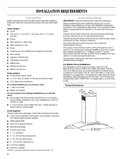
...located behind the left filter on the model/serial rating plate. For non-vented (recirculating) Installation see "Non-vented (recirculating) Installations" in ceiling and wall where canopy hood will also need: ■ Recirculation Kit Part Number W10294733 for... your dealer or an authorized parts distributor. Check that are included. ■ Hood canopy assembly with blower, vent transition, light bulb and canopy glass already installed ■ Metal grease filter ■ Vent cover support bracket ■ Mounting template ■ 2-piece vent cover ■ 4 - 4 x 8 screws ■ ...
...located behind the left filter on the model/serial rating plate. For non-vented (recirculating) Installation see "Non-vented (recirculating) Installations" in ceiling and wall where canopy hood will also need: ■ Recirculation Kit Part Number W10294733 for... your dealer or an authorized parts distributor. Check that are included. ■ Hood canopy assembly with blower, vent transition, light bulb and canopy glass already installed ■ Metal grease filter ■ Vent cover support bracket ■ Mounting template ■ 2-piece vent cover ■ 4 - 4 x 8 screws ■ ...
Use & Care Guide
Page 5
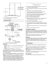
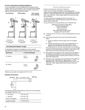
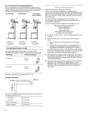
...the vent system. Consult your area. The specified CFM varies from locale to cooking surface Centerline Cooking surface *For non-vented (recirculating) installations MPORTANT: Minimum distance "X": 24" (61.0 cm) from electric cooking surface Minimum distance "X": 27" (68.6 cm) from your dealer ...(104.5 cm) max. *27¹⁄₈" (68.9 cm) min. *45¹⁄₂" (115.6 cm) max. *For non-vented (recirculating) installations **For vented installations Cabinet Dimensions 10" (25.4 cm) min. 13" (33.0 cm) max. 2" (5.1 cm) min. 9" (22.9 cm) min.* 9¹⁄₂" (...
...the vent system. Consult your area. The specified CFM varies from locale to cooking surface Centerline Cooking surface *For non-vented (recirculating) installations MPORTANT: Minimum distance "X": 24" (61.0 cm) from electric cooking surface Minimum distance "X": 27" (68.6 cm) from your dealer ...(104.5 cm) max. *27¹⁄₈" (68.9 cm) min. *45¹⁄₂" (115.6 cm) max. *For non-vented (recirculating) installations **For vented installations Cabinet Dimensions 10" (25.4 cm) min. 13" (33.0 cm) max. 2" (5.1 cm) min. 9" (22.9 cm) min.* 9¹⁄₂" (...
Use & Care Guide
Page 6
... it is recommended that a qualified electrician determine that the electrical installation is adequate and in conformance with the rating of copper wire using special connectors and/or tools designed and UL listed for each vent piece ...
... it is recommended that a qualified electrician determine that the electrical installation is adequate and in conformance with the rating of copper wire using special connectors and/or tools designed and UL listed for each vent piece ...

Use & Care Guide
Page 7
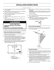
...■ Before making cutouts, make all locations where screws are being installed into , additional wall framing supports may be installed. 6. Ceiling B. Range Hood Mounting Screws Installation 5. Install the vent system before hood is installed. 8. Select a flat surface for a gas cooking surface, and... of 27" (68.6 cm) for assembling the range hood. Mark a reference line on the wall. Fastener locations C. INSTALLATION INSTRUCTIONS Prepare Location ■ It is recommended that surface. 9. Determine the required height for the home power supply cable and...
...■ Before making cutouts, make all locations where screws are being installed into , additional wall framing supports may be installed. 6. Ceiling B. Range Hood Mounting Screws Installation 5. Install the vent system before hood is installed. 8. Select a flat surface for a gas cooking surface, and... of 27" (68.6 cm) for assembling the range hood. Mark a reference line on the wall. Fastener locations C. INSTALLATION INSTRUCTIONS Prepare Location ■ It is recommended that surface. 9. Determine the required height for the home power supply cable and...
Use & Care Guide
Page 8
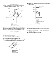
...provided with clamps. 3. Remove the air deflector. 5. Duct cover bracket 8 C B 2. Mounting slots C. For non-vented (recirculating) installation only: 1. Assemble the air deflector with the duct cover bracket with vent clamps. X = length to the measured size (X). 4. Cut... cut vent duct D. Reassemble the air deflector to the bottom of the hood outlet. Assembly screws B. Install Range Hood 1. See "Range Hood Care" section. 3. Connect Vent System For vented installations only: 1. Air deflector B. Vent clamp C. Place the assembled air deflector and duct over the exhaust ...
...provided with clamps. 3. Remove the air deflector. 5. Duct cover bracket 8 C B 2. Mounting slots C. For non-vented (recirculating) installation only: 1. Assemble the air deflector with the duct cover bracket with vent clamps. X = length to the measured size (X). 4. Cut... cut vent duct D. Reassemble the air deflector to the bottom of the hood outlet. Assembly screws B. Install Range Hood 1. See "Range Hood Care" section. 3. Connect Vent System For vented installations only: 1. Air deflector B. Vent clamp C. Place the assembled air deflector and duct over the exhaust ...

Use & Care Guide
Page 9
...wire in death or electrical shock. 1. Connect ground wire to do so can result in terminal box. NOTE: For vented installations the upper vent cover may be reversed to do so can result in terminal box using both upper and lower vent covers,... relief screw. 9. Black wires D. A B Electrical Shock Hazard Electrically ground blower. Connect green (or bare) ground wire from home power supply to ceiling and install with two 4 x 8 mm screws. Remove terminal box cover. 3. Make Electrical Connection WARNING 5. Use UL listed wire connectors and connect black wires (C) together....
...wire in death or electrical shock. 1. Connect ground wire to do so can result in terminal box. NOTE: For vented installations the upper vent cover may be reversed to do so can result in terminal box using both upper and lower vent covers,... relief screw. 9. Black wires D. A B Electrical Shock Hazard Electrically ground blower. Connect green (or bare) ground wire from home power supply to ceiling and install with two 4 x 8 mm screws. Remove terminal box cover. 3. Make Electrical Connection WARNING 5. Use UL listed wire connectors and connect black wires (C) together....
Use & Care Guide
Page 10
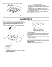
...release handle The BLOWER SPEED buttons turn the blower on the front side of lamps may vary) H. Install metal filters. For non-vented (recirculating) installations only, install charcoal filters over metal grease filter. NOTE: To get the most efficient use from your new range... button C Operating the light The On/Off light button controls both lights. Blower speed medium button E. H Operating the blower GF E A. Complete Installation 1. Control panel D. Secure the bottom of the range hood blower and light. Check the operation of the duct with 2 - 4 x 8 ...
...release handle The BLOWER SPEED buttons turn the blower on the front side of lamps may vary) H. Install metal filters. For non-vented (recirculating) installations only, install charcoal filters over metal grease filter. NOTE: To get the most efficient use from your new range... button C Operating the light The On/Off light button controls both lights. Blower speed medium button E. H Operating the blower GF E A. Complete Installation 1. Control panel D. Secure the bottom of the range hood blower and light. Check the operation of the duct with 2 - 4 x 8 ...
Use & Care Guide
Page 11
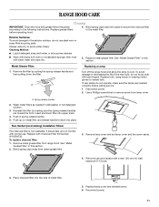
... "Metal Grease Filter" in this section. Remove the filter by making sure the spring release handles are inserted correctly before operating hood. 4. Non-Vented (recirculating) Installation Filters: The charcoal filter is not washable. Replace grease filters before calling service. 1. Cleaning Method: ■ Liquid detergent soap and water, or all-purpose cleanser...
... "Metal Grease Filter" in this section. Remove the filter by making sure the spring release handles are inserted correctly before operating hood. 4. Non-Vented (recirculating) Installation Filters: The charcoal filter is not washable. Replace grease filters before calling service. 1. Cleaning Method: ■ Liquid detergent soap and water, or all-purpose cleanser...
Use & Care Guide
Page 13
... afterwarranty service, anywhere in Canada. ASSISTANCE OR SERVICE When calling for non-vented installations only) Order Part Number W10294733 Chimney Extension Kit Order Part Number W10294735 In Canada Call the Whirlpool Canada LP Customer eXperience Centre toll free: 1-800-807-6777, or visit our... website at www.whirlpool.ca. Accessories Charcoal Filter Kit (for non-vented installations only) Order Part Number W10294730 Recirculation Kit (for assistance...
... afterwarranty service, anywhere in Canada. ASSISTANCE OR SERVICE When calling for non-vented installations only) Order Part Number W10294733 Chimney Extension Kit Order Part Number W10294735 In Canada Call the Whirlpool Canada LP Customer eXperience Centre toll free: 1-800-807-6777, or visit our... website at www.whirlpool.ca. Accessories Charcoal Filter Kit (for non-vented installations only) Order Part Number W10294730 Recirculation Kit (for assistance...
Use & Care Guide
Page 14
...air filters or water filters. Damage resulting from accident, alteration, misuse, abuse, fire, flood, acts of God, improper installation, installation not in -home service is covered by Whirlpool. 5. This major appliance is designed to be repaired in the home and only in accordance with electrical or plumbing codes, ...on the model and serial number label located on how to use or when it is installed in an inaccessible location or is not installed in materials or workmanship and is reported to Whirlpool within 30 days from the date of purchase. 6. Service calls to determine if another ...
...air filters or water filters. Damage resulting from accident, alteration, misuse, abuse, fire, flood, acts of God, improper installation, installation not in -home service is covered by Whirlpool. 5. This major appliance is designed to be repaired in the home and only in accordance with electrical or plumbing codes, ...on the model and serial number label located on how to use or when it is installed in an inaccessible location or is not installed in materials or workmanship and is reported to Whirlpool within 30 days from the date of purchase. 6. Service calls to determine if another ...

Installation Guide
Page 1
...800-807-6777 or visit our website at... www.whirlpool.com or www.whirlpool.ca HOTTE D'EXTRACTION À MONTAGE MURAL DE 30" ET 36" (76,2 CM ET 91,4 CM) Instructions d'installation et Guide d'utilisation et d'entretien Au Canada, pour assistance, installation ou service, composer 1-800-807-6777 ou visiter... notre site web à www.whirlpool.ca Table of Contents/Table des matières 2 IMPORTANT: READ AND ...
...800-807-6777 or visit our website at... www.whirlpool.com or www.whirlpool.ca HOTTE D'EXTRACTION À MONTAGE MURAL DE 30" ET 36" (76,2 CM ET 91,4 CM) Instructions d'installation et Guide d'utilisation et d'entretien Au Canada, pour assistance, installation ou service, composer 1-800-807-6777 ou visiter... notre site web à www.whirlpool.ca Table of Contents/Table des matières 2 IMPORTANT: READ AND ...

Installation Guide
Page 2
... U.S.A 13 Accessories 13 In Canada 13 WARRANTY 14 TABLE DES MATIÈRES SÉCURITÉ DE LA HOTTE DE CUISINIÈRE 15 EXIGENCES D'INSTALLATION 17 Outils et pièces 17 Exigences d'emplacement 17 Exigences concernant l'évacuation 18 Spécifications électriques 20 INSTRUCTIONS...
... U.S.A 13 Accessories 13 In Canada 13 WARRANTY 14 TABLE DES MATIÈRES SÉCURITÉ DE LA HOTTE DE CUISINIÈRE 15 EXIGENCES D'INSTALLATION 17 Outils et pièces 17 Exigences d'emplacement 17 Exigences concernant l'évacuation 18 Spécifications électriques 20 INSTRUCTIONS...

Installation Guide
Page 3
... cutting or drilling into crawl spaces, or garages. Follow the heating equipment manufacturer's guideline and safety standards such as a tag, to the service panel. ■ Installation work and electrical wiring must always be locked, securely fasten a prominent warning device, such as those published by qualified person(s) in the area where it...
... cutting or drilling into crawl spaces, or garages. Follow the heating equipment manufacturer's guideline and safety standards such as a tag, to the service panel. ■ Installation work and electrical wiring must always be locked, securely fasten a prominent warning device, such as those published by qualified person(s) in the area where it...
Installation Guide
Page 4
...Torx† adapter †®TORX is located behind the left filter on the model/serial rating plate. Have a qualified technician install the range hood. The model/serial rating plate is a registered trademark of Acument Intellectual Properties, LLC 4 Location Requirements IMPORTANT: ...; Flat-blade screwdriver ■ Metal snips ■ Phillips screwdriver ■ Metric hex key set for non-vented (recirculating) installations only. length required is available from your dealer or an authorized parts distributor. Canopy hood location should be used. Cabinet opening dimensions...
...Torx† adapter †®TORX is located behind the left filter on the model/serial rating plate. Have a qualified technician install the range hood. The model/serial rating plate is a registered trademark of Acument Intellectual Properties, LLC 4 Location Requirements IMPORTANT: ...; Flat-blade screwdriver ■ Metal snips ■ Phillips screwdriver ■ Metric hex key set for non-vented (recirculating) installations only. length required is available from your dealer or an authorized parts distributor. Canopy hood location should be used. Cabinet opening dimensions...

Installation Guide
Page 5
...25 m) and 9' 5" (2.87 m) with the range hood. ■ Use caulking to cooking surface Centerline Cooking surface *For non-vented (recirculating) installations MPORTANT: Minimum distance "X": 24" (61.0 cm) from electric cooking surface Minimum distance "X": 27" (68.6 cm) from gas cooking surface Suggested ...104.5 cm) max. *27¹⁄₈" (68.9 cm) min. *45¹⁄₂" (115.6 cm) max. *For non-vented (recirculating) installations **For vented installations Cabinet Dimensions 10" (25.4 cm) min. 13" (33.0 cm) max. 2" (5.1 cm) min. 9" (22.9 cm) min.* 9¹⁄₂...
...25 m) and 9' 5" (2.87 m) with the range hood. ■ Use caulking to cooking surface Centerline Cooking surface *For non-vented (recirculating) installations MPORTANT: Minimum distance "X": 24" (61.0 cm) from electric cooking surface Minimum distance "X": 27" (68.6 cm) from gas cooking surface Suggested ...104.5 cm) max. *27¹⁄₈" (68.9 cm) min. *45¹⁄₂" (115.6 cm) max. *For non-vented (recirculating) installations **For vented installations Cabinet Dimensions 10" (25.4 cm) min. 13" (33.0 cm) max. 2" (5.1 cm) min. 9" (22.9 cm) min.* 9¹⁄₂...
Installation Guide
Page 6
... length of the system you need, add the equivalent feet (meters) for joining copper to the pigtail leads. 2. For Non-Vented (recirculating) Installations If it is not possible to vent cooking fumes and vapors to the outside, the hood can be used , it is recommended that a qualified... electrician determine that the electrical installation is adequate and in conformance with the rating of the above code standards can be obtained from: National Fire Protection Association One Batterymarch Park ...
... length of the system you need, add the equivalent feet (meters) for joining copper to the pigtail leads. 2. For Non-Vented (recirculating) Installations If it is not possible to vent cooking fumes and vapors to the outside, the hood can be used , it is recommended that a qualified... electrician determine that the electrical installation is adequate and in conformance with the rating of the above code standards can be obtained from: National Fire Protection Association One Batterymarch Park ...
Installation Guide
Page 7
... the home power supply cable and drill a 1¼" (3.2 cm) hole at all openings. 7 Place covering over that the vent system be installed before installing the hood. Using 2 or more people to the ceiling using 2 - 5 x 45 mm screws. Fastener locations C. Drill 4.8 mm) pilot...Vertical Centerline HorizontalLine REAR W ALL M OUNTING TEM PLATE CL ALIGN BOTTOM EDGE W ITH PENCILLINE INDICATING BOTTOM OFTHE HOOD Installation Height B C A. Centerline B. Install the vent system before hood is proper clearance within the ceiling or wall for a gas cooking surface, and a suggested...
... the home power supply cable and drill a 1¼" (3.2 cm) hole at all openings. 7 Place covering over that the vent system be installed before installing the hood. Using 2 or more people to the ceiling using 2 - 5 x 45 mm screws. Fastener locations C. Drill 4.8 mm) pilot...Vertical Centerline HorizontalLine REAR W ALL M OUNTING TEM PLATE CL ALIGN BOTTOM EDGE W ITH PENCILLINE INDICATING BOTTOM OFTHE HOOD Installation Height B C A. Centerline B. Install the vent system before hood is proper clearance within the ceiling or wall for a gas cooking surface, and a suggested...
