
English Manual
Page 1
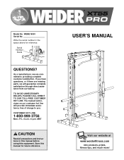
... and instructions in the space above for future reference. ® USER'S MANUAL Visit our website at www.weiderfitness.com new products, prizes, fitness tips, and much more! The trained technicians on our customer hot line will guarantee complete satisfaction through direct assistance from our factory. CUSTOMER HOT LINE: 1-800-999-3756 Mon.-Fri., 6 a.m.-6 p.m. Serial Number Decal QUESTIONS? Write the serial number...
... and instructions in the space above for future reference. ® USER'S MANUAL Visit our website at www.weiderfitness.com new products, prizes, fitness tips, and much more! The trained technicians on our customer hot line will guarantee complete satisfaction through direct assistance from our factory. CUSTOMER HOT LINE: 1-800-999-3756 Mon.-Fri., 6 a.m.-6 p.m. Serial Number Decal QUESTIONS? Write the serial number...
English Manual
Page 2
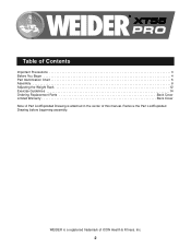
® Table of Contents Important Precautions 3 Before You Begin 4 Part Identification Chart 5 Assembly 6 Adjusting the Weight Rack 12 Exercise Guidelines 14 Ordering Replacement Parts Back Cover Limited Warranty Back Cover Note: A Part List/Exploded Drawing is a registered trademark of this manual. WEIDER is attached in the center of ICON Health & Fitness, Inc. 2 Remove the Part List/Exploded Drawing before beginning assembly.
® Table of Contents Important Precautions 3 Before You Begin 4 Part Identification Chart 5 Assembly 6 Adjusting the Weight Rack 12 Exercise Guidelines 14 Ordering Replacement Parts Back Cover Limited Warranty Back Cover Note: A Part List/Exploded Drawing is a registered trademark of this manual. WEIDER is attached in the center of ICON Health & Fitness, Inc. 2 Remove the Part List/Exploded Drawing before beginning assembly.
English Manual
Page 3
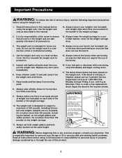
... Friday, 6 a.m. Always remove the lat bar when performing an exercise that does not use the weight rack. WARNING: Before beginning this product. 3 If you use the bench. 4. Always set both weight gliders and both safety spotters at all instructions before using. Do not use of this or any worn parts immediately. 6. If the decal is designed to order a free replacement decal. Mountain Time, to support a maximum of...
... Friday, 6 a.m. Always remove the lat bar when performing an exercise that does not use the weight rack. WARNING: Before beginning this product. 3 If you use the bench. 4. Always set both weight gliders and both safety spotters at all instructions before using. Do not use of this or any worn parts immediately. 6. If the decal is designed to order a free replacement decal. Mountain Time, to support a maximum of...
English Manual
Page 4
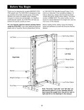
... parts that are determined relative to help you achieve the specific results you for selecting the versatile WEIDER® XT55 PRO weight rack. The XT55 PRO is WEBE19301. To help us assist you develop every major muscle group of this manual. 4 The model number is designed to a user standing with his back toward the weight rack; Lat Tower Upright Right Side High Pulley Station Lat Bar Weight Guide Left Side Weight...
... parts that are determined relative to help you achieve the specific results you for selecting the versatile WEIDER® XT55 PRO weight rack. The XT55 PRO is WEBE19301. To help us assist you develop every major muscle group of this manual. 4 The model number is designed to a user standing with his back toward the weight rack; Lat Tower Upright Right Side High Pulley Station Lat Bar Weight Guide Left Side Weight...
English Manual
Page 5
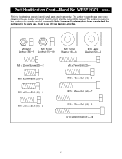
... Washer (6)-14 M10 Large Washer (58)-6 M8 x 20mm Screw (50)-2 M10 x 20mm Bolt (26)-2 M10 x 25mm Bolt (43)-4 M10 x 30mm Bolt (38)-2 M8 x 70mm Bolt (30)-1 M10 x 45mm Bolt (40)-3 M10 x 65mm Bolt (56)-7 M10 x 75mm Bolt (39)-2 M10 x 80mm Bolt (41)-24 5 Note: Some small parts may have been pre-attached. The number following the key number is the key number of this manual. Part Identification Chart-Model No.
... Washer (6)-14 M10 Large Washer (58)-6 M8 x 20mm Screw (50)-2 M10 x 20mm Bolt (26)-2 M10 x 25mm Bolt (43)-4 M10 x 30mm Bolt (38)-2 M8 x 70mm Bolt (30)-1 M10 x 45mm Bolt (40)-3 M10 x 65mm Bolt (56)-7 M10 x 75mm Bolt (39)-2 M10 x 80mm Bolt (41)-24 5 Note: Some small parts may have been pre-attached. The number following the key number is the key number of this manual. Part Identification Chart-Model No.
English Manual
Page 6
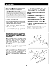
...-assembled. Press a 60mm Square Inner Cap (55) into the end of a Base (7). Assembly Before beginning assembly, carefully read the following tools (not included): • Two adjustable wrenches • One rubber mallet • One standard screwdriver • One phillips screwdriver • Lubricant, such as grease or petroleum jelly, and soapy water. This manual is completed. • Tighten all parts in the assembly steps...
...-assembled. Press a 60mm Square Inner Cap (55) into the end of a Base (7). Assembly Before beginning assembly, carefully read the following tools (not included): • Two adjustable wrenches • One rubber mallet • One standard screwdriver • One phillips screwdriver • Lubricant, such as grease or petroleum jelly, and soapy water. This manual is completed. • Tighten all parts in the assembly steps...
English Manual
Page 7
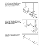
... the Uprights are oriented exactly as shown. Attach the Weight Guides to each Base (7) using M10 x 75mm Bolts (39), M10 Small Washers (6), and M10 Nylon Locknuts (11). Insert a Weight Guide (18) into the indicated hole in each end of the Locking Bar (34). Slide the Barbell (35) into each Base (7). 3. Do not tighten the Nylon Locknuts yet. 1 41 7 1 12 12 4. Press...
... the Uprights are oriented exactly as shown. Attach the Weight Guides to each Base (7) using M10 x 75mm Bolts (39), M10 Small Washers (6), and M10 Nylon Locknuts (11). Insert a Weight Guide (18) into the indicated hole in each end of the Locking Bar (34). Slide the Barbell (35) into each Base (7). 3. Do not tighten the Nylon Locknuts yet. 1 41 7 1 12 12 4. Press...
English Manual
Page 8
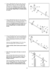
... Bolt (43). Note: This step requires the help of a Weight Adapter (33). Make sure the Right Weight Glider is oriented exactly as shown. 23 Slide the assembled Locking Bar (34) and the Right and Left Weight Gliders (31, 32) onto the Weight Guides (18). Make sure the Locking Bar and Weight Gliders are oriented exactly as shown. 35 29 32 50 29 8. 6. Press...
... Bolt (43). Note: This step requires the help of a Weight Adapter (33). Make sure the Right Weight Glider is oriented exactly as shown. 23 Slide the assembled Locking Bar (34) and the Right and Left Weight Gliders (31, 32) onto the Weight Guides (18). Make sure the Locking Bar and Weight Gliders are oriented exactly as shown. 35 29 32 50 29 8. 6. Press...
English Manual
Page 9
...12. Insert an M10 x 20mm Bolt (26) into the bracket on the Rear Base (3). Slide the Carriage Stop (28) onto the lower end of the weight tube on the Weight Carriage. Attach the Rear Upright to the Rear Base using two M10 x 30mm Bolts (38) and two M10 Small Washers...Attach the Top Crossbar to the Weight Guides (18) using two M10 x 65mm Bolts (56), four M10 Small Washers (6), and two M10 Nylon Locknuts (11). Press 50mm Round Inner Caps (25) into the top of the Weight Carriage (22). Do not tighten the Nylon Locknuts yet. Press a Carriage Bushing (27) into the ends of the Rear Upright...
...12. Insert an M10 x 20mm Bolt (26) into the bracket on the Rear Base (3). Slide the Carriage Stop (28) onto the lower end of the weight tube on the Weight Carriage. Attach the Rear Upright to the Rear Base using two M10 x 30mm Bolts (38) and two M10 Small Washers...Attach the Top Crossbar to the Weight Guides (18) using two M10 x 65mm Bolts (56), four M10 Small Washers (6), and two M10 Nylon Locknuts (11). Press 50mm Round Inner Caps (25) into the top of the Weight Carriage (22). Do not tighten the Nylon Locknuts yet. Press a Carriage Bushing (27) into the ends of the Rear Upright...
English Manual
Page 10
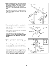
13. Attach the Pulley Bar (53) to the Rear Upright using two M10 x 65mm Bolts (56), four M10 Small Washers (6), and two M10 Nylon Locknuts (11). Route the High Cable up through the Pulley Bar (53), around another Pulley (5) and through the indicated slot in the indicated location. Do not overtighten the Nylon Locknut. Attach the Pulley Bar to the Top Crossbar (9) using an M10 x 65mm Bolt (56), two...
13. Attach the Pulley Bar (53) to the Rear Upright using two M10 x 65mm Bolts (56), four M10 Small Washers (6), and two M10 Nylon Locknuts (11). Route the High Cable up through the Pulley Bar (53), around another Pulley (5) and through the indicated slot in the indicated location. Do not overtighten the Nylon Locknut. Attach the Pulley Bar to the Top Crossbar (9) using an M10 x 65mm Bolt (56), two...

English Manual
Page 11
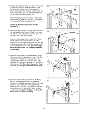
... Base Crossbar (20) using an M10 x 45mm Bolt (40) and an M10 Nylon Locknut (11). Do not overtighten the Nylon Locknut; Route the Low Cable (8) around a Pulley (5). Hold a Cable Trap (21) against the Pulley 18 and attach a Pulley Plate (19) to the lowest holes in the Weight Carriage (22). Route the indicated end of the Low Cable (8) 19 around a Pulley (5) as shown. 17...
... Base Crossbar (20) using an M10 x 45mm Bolt (40) and an M10 Nylon Locknut (11). Do not overtighten the Nylon Locknut; Route the Low Cable (8) around a Pulley (5). Hold a Cable Trap (21) against the Pulley 18 and attach a Pulley Plate (19) to the lowest holes in the Weight Carriage (22). Route the indicated end of the Low Cable (8) 19 around a Pulley (5) as shown. 17...
English Manual
Page 12
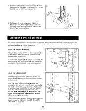
... in the Uprights. Note: Always start an exercise with the WEIDER® PRO XT15 weight bench (model number WEBE0910). USING THE WEIGHT ADAPTER A Weight Adapter (42) and Pin (52) have been included for the exercise. 1 1 To do this, stand in front of the Low Cable (8) to a new position and turn it by inserting the Pin (52) through the leg lever as shown. Make sure all remaining parts will move during the exercise. 24...
... in the Uprights. Note: Always start an exercise with the WEIDER® PRO XT15 weight bench (model number WEBE0910). USING THE WEIGHT ADAPTER A Weight Adapter (42) and Pin (52) have been included for the exercise. 1 1 To do this, stand in front of the Low Cable (8) to a new position and turn it by inserting the Pin (52) through the leg lever as shown. Make sure all remaining parts will move during the exercise. 24...
English Manual
Page 13
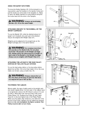
... To use of the Lat Bar. Always secure weights with Weight Clips (51). ATTACHING THE LAT BAR TO THE HIGH PULLEY STATION OR THE LOW PULLEY STATION To use the high pulley station or the low pulley station, attach the Lat Bar (16) to the High Cable (13) or the Low Cable (not shown) using a Cable Clip (14). Reattach the Pulley (5) and Cable Trap (21) to the next higher hole in the Uprights...
... To use of the Lat Bar. Always secure weights with Weight Clips (51). ATTACHING THE LAT BAR TO THE HIGH PULLEY STATION OR THE LOW PULLEY STATION To use the high pulley station or the low pulley station, attach the Lat Bar (16) to the High Cable (13) or the Low Cable (not shown) using a Cable Clip (14). Reattach the Pulley (5) and Cable Trap (21) to the next higher hole in the Uprights...
English Manual
Page 14
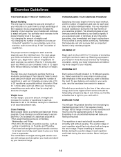
... perform. Weight Loss To lose weight, use a low amount of weight and increase the number of aerobic exercise, such as one day of repetitions). The repetitions in each set . Rest for 1 minute after each exercise you feeling exhausted. formed (A "repetition" is : • Plan weight training workouts on Tuesday and Thursday. • Rest from exercising by at your breath. 14 Remember that is a series of...
... perform. Weight Loss To lose weight, use a low amount of weight and increase the number of aerobic exercise, such as one day of repetitions). The repetitions in each set . Rest for 1 minute after each exercise you feeling exhausted. formed (A "repetition" is : • Plan weight training workouts on Tuesday and Thursday. • Rest from exercising by at your breath. 14 Remember that is a series of...
English Manual
Page 15
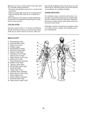
... each workout is to make exercise a regular and enjoyable part of your arms and legs. Remember, the key to achieving the greatest results is very effective for increasing flexibility. Pectoralis Major (chest) A C. Tibialis Anterior (front of calf) F L L. Rhomboideus (upper back) P. Stretching at the end of every month. Quadriceps (front of thigh) I Q. Rectus Abdominus (stomach) G M. Spinae Erectors (lower back) K T. Move...
... each workout is to make exercise a regular and enjoyable part of your arms and legs. Remember, the key to achieving the greatest results is very effective for increasing flexibility. Pectoralis Major (chest) A C. Tibialis Anterior (front of calf) F L L. Rhomboideus (upper back) P. Stretching at the end of every month. Quadriceps (front of thigh) I Q. Rectus Abdominus (stomach) G M. Spinae Erectors (lower back) K T. Move...
English Manual
Page 16
... rights which warranty claim is limited to give the following information when calling: • The MODEL NUMBER of the product (WEBE19301) • The NAME of the product (WEIDER XT55 PRO weight rack) • The SERIAL NUMBER of the product (see the front cover of this manual) • The KEY NUMBER and DESCRIPTION of the desired part(s) (see the PART LIST and the EXPLODED DRAWING in its authorized service centers...
... rights which warranty claim is limited to give the following information when calling: • The MODEL NUMBER of the product (WEBE19301) • The NAME of the product (WEIDER XT55 PRO weight rack) • The SERIAL NUMBER of the product (see the front cover of this manual) • The KEY NUMBER and DESCRIPTION of the desired part(s) (see the PART LIST and the EXPLODED DRAWING in its authorized service centers...
English Manual
Page 17
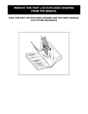
REMOVE THIS PART LIST/EXPLODED DRAWING FROM THE MANUAL SAVE THIS PART LIST/EXPLODED DRAWING AND THE USER'S MANUAL FOR FUTURE REFERENCE 81
REMOVE THIS PART LIST/EXPLODED DRAWING FROM THE MANUAL SAVE THIS PART LIST/EXPLODED DRAWING AND THE USER'S MANUAL FOR FUTURE REFERENCE 81
English Manual
Page 18
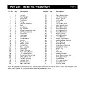
.... Specifications are subject to change without notice. See the back cover of the user's manual for information about ordering replacement parts. Part List-Model No. Qty. WEBE19301 R1200A Key No. Description 1 2 Upright 2 1 Rear Upright 3 1 Rear Base 4 1 Foot Plate 5 6 Pulley 6 14 M10 Small Washer 7 2 Base 8 1 Low Cable 9 1 Top Crossbar 10 2 50mm Square Inner Cap 11 40 M10 Nylon Locknut 12 8 Joint Plate 13 1 High Cable 14 1 Cable Clip 15 6 Pulley Spacer 16 1 Lat Bar...
.... Specifications are subject to change without notice. See the back cover of the user's manual for information about ordering replacement parts. Part List-Model No. Qty. WEBE19301 R1200A Key No. Description 1 2 Upright 2 1 Rear Upright 3 1 Rear Base 4 1 Foot Plate 5 6 Pulley 6 14 M10 Small Washer 7 2 Base 8 1 Low Cable 9 1 Top Crossbar 10 2 50mm Square Inner Cap 11 40 M10 Nylon Locknut 12 8 Joint Plate 13 1 High Cable 14 1 Cable Clip 15 6 Pulley Spacer 16 1 Lat Bar...
English Manual
Page 19
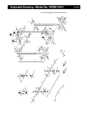
... 43 46 42 46 11 20 11 11 7 12 11 6 12 52 45 45 55 6 39 11 18 55 57 41 41 R1200A Exploded Drawing-Model No. WEBE19301
... 43 46 42 46 11 20 11 11 7 12 11 6 12 52 45 45 55 6 39 11 18 55 57 41 41 R1200A Exploded Drawing-Model No. WEBE19301


