

English Manual
Page 2
...and begin cooling down. 14. Table of Contents IMPORTANT PRECAUTIONS 2 BEFORE YOU BEGIN 3 ASSEMBLY 4 HOW TO USE THE HOME GYM SYSTEM 22 WEIGHT RESISTANCE CHART 24 TROUBLE-SHOOTING AND MAINTENANCE 25 CABLE DIAGRAMS 26 ORDERING REPLACEMENT PARTS Back Cover LIMITED WARRANTY Back Cover Note: A PART IDENTIFICATION CHART...When using . Never release the press arm, butterfly arms, leg lever, leg press plate, lat bar, ab strap, or nylon strap while weights are adequately informed of 12 and pets away from the home gym system at any worn parts immediately. 5. The home gym system is clipped ...
...and begin cooling down. 14. Table of Contents IMPORTANT PRECAUTIONS 2 BEFORE YOU BEGIN 3 ASSEMBLY 4 HOW TO USE THE HOME GYM SYSTEM 22 WEIGHT RESISTANCE CHART 24 TROUBLE-SHOOTING AND MAINTENANCE 25 CABLE DIAGRAMS 26 ORDERING REPLACEMENT PARTS Back Cover LIMITED WARRANTY Back Cover Note: A PART IDENTIFICATION CHART...When using . Never release the press arm, butterfly arms, leg lever, leg press plate, lat bar, ab strap, or nylon strap while weights are adequately informed of 12 and pets away from the home gym system at any worn parts immediately. 5. The home gym system is clipped ...

English Manual
Page 3
... You Begin Thank you want. Whether your goal is to achieve the specific results you for selecting the versatile WEIDER¨ PRO 9925 Training System. The serial number can be found on the weight bench in . If a decal is missing, or if it is WESY93191. until 6 p.m. Mountain Time, ...DIMENSIONS: Height: 78 in the two locations shown. Apply the replacement decal to order a replacement decal. The WEIDER¨ PRO 9925 offers a selection of weight stations designed to the WEIDER¨ PRO 9925 (see the front cover of the body. If you , please note the product model number and serial ...
... You Begin Thank you want. Whether your goal is to achieve the specific results you for selecting the versatile WEIDER¨ PRO 9925 Training System. The serial number can be found on the weight bench in . If a decal is missing, or if it is WESY93191. until 6 p.m. Mountain Time, ...DIMENSIONS: Height: 78 in the two locations shown. Apply the replacement decal to order a replacement decal. The WEIDER¨ PRO 9925 offers a selection of weight stations designed to the WEIDER¨ PRO 9925 (see the front cover of the body. If you , please note the product model number and serial ...

English Manual
Page 4
... allow you to walk all parts in assembly, we have a socket set, a set of open the parts bag labeled for each other and with the weights. Seat Assembly Completes the seat and backrest that all moving arms with many small parts. Clearing the Workspace Clear a workspace that is completed. ¥ One...
... allow you to walk all parts in assembly, we have a socket set, a set of open the parts bag labeled for each other and with the weights. Seat Assembly Completes the seat and backrest that all moving arms with many small parts. Clearing the Workspace Clear a workspace that is completed. ¥ One...

English Manual
Page 5
.... 56 Insert four 5/16Ó x 2 1/2Ó Carriage Bolts (49) up through the Press Base (13). Attach the Press Base (13) to the Weight Base (14) with two 5/16Ó x 2 3/4Ó Bolts (55), two 5/16Ó Washers (20) and two 5/16Ó Nylon Locknuts (40). Hand tighten two 5/16...Ó Nylon Locknuts (40) onto the Carriage Bolts. FRAME ASSEMBLY 1 1. cated ends of the Weight Base. 14 Insert two 5/16Ó x 2 1/2Ó Carriage Bolts (49) up through the indicated holes in the box above. Locate and open the parts bags...
.... 56 Insert four 5/16Ó x 2 1/2Ó Carriage Bolts (49) up through the Press Base (13). Attach the Press Base (13) to the Weight Base (14) with two 5/16Ó x 2 3/4Ó Bolts (55), two 5/16Ó Washers (20) and two 5/16Ó Nylon Locknuts (40). Hand tighten two 5/16...Ó Nylon Locknuts (40) onto the Carriage Bolts. FRAME ASSEMBLY 1 1. cated ends of the Weight Base. 14 Insert two 5/16Ó x 2 1/2Ó Carriage Bolts (49) up through the indicated holes in the box above. Locate and open the parts bags...

English Manual
Page 6
... 20 Attach the other end of the Butterfly Frame (3). Slide the Front Seat Frame (8) onto the indicated 5/16Ó x 2 1/2Ó Carriage Bolts (49) in the Weight Base (14). Attach the Rear Seat Frame (16) to the bracket on the side shown. Hand tighten two 5/16Ó Nylon Locknuts (40) onto the...
... 20 Attach the other end of the Butterfly Frame (3). Slide the Front Seat Frame (8) onto the indicated 5/16Ó x 2 1/2Ó Carriage Bolts (49) in the Weight Base (14). Attach the Rear Seat Frame (16) to the bracket on the side shown. Hand tighten two 5/16Ó Nylon Locknuts (40) onto the...
English Manual
Page 7
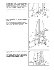
... 27 23 23 9. Make sure the pin grooves are in the pin grooves in the same manner. 23 23 40 8. Press a Weight Tube Bumper (26) into each stack of Weight Guides (23). Insert a Weight Tube (25) into one of the brack- 7 ets on the indicated side of each set of... Weights (90). Make sure the pins on the Weight Tubes are on the Weight Base (14). Attach the other Weight Guides (23) in the upper Weights. 25 26 90 90 Pin Grooves 7 7. Insert two Weight Guides (23) into each Weight 9 Tube (25). Attach the lower ends of ...
... 27 23 23 9. Make sure the pin grooves are in the pin grooves in the same manner. 23 23 40 8. Press a Weight Tube Bumper (26) into each stack of Weight Guides (23). Insert a Weight Tube (25) into one of the brack- 7 ets on the indicated side of each set of... Weights (90). Make sure the pins on the Weight Tubes are on the Weight Base (14). Attach the other Weight Guides (23) in the upper Weights. 25 26 90 90 Pin Grooves 7 7. Insert two Weight Guides (23) into each Weight 9 Tube (25). Attach the lower ends of ...

English Manual
Page 8
... two 5/16Ó x 2 3/4Ó Bolts (55), a 20 3 Support Plate (95) and two 5/16Ó Nylon Locknuts 2 (40). Attach the upper ends of one set of Weight Guides (23) to the Leg Press Upright (4) with 11 two 5/16Ó x 2 3/4Ó Bolts (55), two 5/16Ó Washers (20) and two 5/16Ó Nylon... (24) as shown. Do not tighten the Nylon Locknuts yet. 1 12. Attach the upper ends of the other set of Weight Guides (23) in the same manner. Slide a Top Weight onto each set of the holes in steps 1 through 12. 12 40 2 40 40 4 40 69 69 23 67 67 23 8 Lubricate...
... two 5/16Ó x 2 3/4Ó Bolts (55), a 20 3 Support Plate (95) and two 5/16Ó Nylon Locknuts 2 (40). Attach the upper ends of one set of Weight Guides (23) to the Leg Press Upright (4) with 11 two 5/16Ó x 2 3/4Ó Bolts (55), two 5/16Ó Washers (20) and two 5/16Ó Nylon... (24) as shown. Do not tighten the Nylon Locknuts yet. 1 12. Attach the upper ends of the other set of Weight Guides (23) in the same manner. Slide a Top Weight onto each set of the holes in steps 1 through 12. 12 40 2 40 40 4 40 69 69 23 67 67 23 8 Lubricate...

English Manual
Page 13
Place a 3/8Ó x 1 1/4Ó Weight Spacer (32) and a 1/2Ó Washer (68) on the Pulley Covers as shown. Attach a 3 1/2Ó ...that the Cable and Pulley move smoothly. 29. Make sure the Cable is necessary to lift the Weight Tube (25) with the Top Weight (24) slightly to pivot. 91 92 87 28. The Cable must be routed from the direction... Locate the Rear Cable (87)Ñthis is the shortest 27 Cable. Slide one end of the Weight Tube (25) until the Weight Spacer (32) touches the Weight Tube. Thread another 5/16Ó Nylon Jam Nut (91) onto the Bolt, but do not fully...
Place a 3/8Ó x 1 1/4Ó Weight Spacer (32) and a 1/2Ó Washer (68) on the Pulley Covers as shown. Attach a 3 1/2Ó ...that the Cable and Pulley move smoothly. 29. Make sure the Cable is necessary to lift the Weight Tube (25) with the Top Weight (24) slightly to pivot. 91 92 87 28. The Cable must be routed from the direction... Locate the Rear Cable (87)Ñthis is the shortest 27 Cable. Slide one end of the Weight Tube (25) until the Weight Spacer (32) touches the Weight Tube. Thread another 5/16Ó Nylon Jam Nut (91) onto the Bolt, but do not fully...

English Manual
Page 18
...3 3/4Ó Bolt (76), two 3/8Ó Washers (38) and a 3/8Ó Nylon Jam Nut (43). Do not overtighten the Nylon Locknut; Attach the Pulley to lift the Weight Tube (25) with a 3/8Ó x 2Ó Bolt (50) and a 3/8Ó Nylon Locknut (42). Thread the end of the High Cable (85) into the upper end...around a 3 1/2Ó Pulley (82) in the direction shown. Thread a 1/2Ó Plain Nut (83) onto the end of the Weight Tube (25). Place a 1/2Ó Washer (68) and a 3/8Ó x 1 1/4Ó Weight Spacer (32) on the Pulley Covers as shown. 49 43 38 94 Wide Tab 82 Post 76 86 38 1 18 Make...
...3 3/4Ó Bolt (76), two 3/8Ó Washers (38) and a 3/8Ó Nylon Jam Nut (43). Do not overtighten the Nylon Locknut; Attach the Pulley to lift the Weight Tube (25) with a 3/8Ó x 2Ó Bolt (50) and a 3/8Ó Nylon Locknut (42). Thread the end of the High Cable (85) into the upper end...around a 3 1/2Ó Pulley (82) in the direction shown. Thread a 1/2Ó Plain Nut (83) onto the end of the Weight Tube (25). Place a 1/2Ó Washer (68) and a 3/8Ó x 1 1/4Ó Weight Spacer (32) on the Pulley Covers as shown. 49 43 38 94 Wide Tab 82 Post 76 86 38 1 18 Make...

English Manual
Page 20
Attach a Pro Pulley (62) inside the bracket on the Weight Base (14) with a 3/8Ó x 3 3/4Ó Bolt (76), two 3/8Ó Washers (38) and a 3/8Ó Nylon Jam Nut (43). Attach the Pulley and two Pulley Covers (94) ... wide tab on the 43 Pulley Covers as shown. 38 43 Wide Tab 82 94 94 76 38 55. Orient the wide tab on the Weight Base (14). Attach the Pulley and two Pulley Covers (94) to the Ab Upright (1) with a 3/8Ó x 3 3/4Ó Bolt (76), two 3/8Ó Washers (38) and a 3/8Ó...
Attach a Pro Pulley (62) inside the bracket on the Weight Base (14) with a 3/8Ó x 3 3/4Ó Bolt (76), two 3/8Ó Washers (38) and a 3/8Ó Nylon Jam Nut (43). Attach the Pulley and two Pulley Covers (94) ... wide tab on the 43 Pulley Covers as shown. 38 43 Wide Tab 82 94 94 76 38 55. Orient the wide tab on the Weight Base (14). Attach the Pulley and two Pulley Covers (94) to the Ab Upright (1) with a 3/8Ó x 3 3/4Ó Bolt (76), two 3/8Ó Washers (38) and a 3/8Ó...

English Manual
Page 22
... of the cables does not move smoothly over the pulleys. 61. IMPORTANT: If the cables are not properly installed, they may be damaged when heavy weight is any slack in HOW TO USE THE HOME GYM SYSTEM, beginning on page 25. 22 Attach the Curl Pad (77) to be explained in...
... of the cables does not move smoothly over the pulleys. 61. IMPORTANT: If the cables are not properly installed, they may be damaged when heavy weight is any slack in HOW TO USE THE HOME GYM SYSTEM, beginning on page 25. 22 Attach the Curl Pad (77) to be explained in...

English Manual
Page 23
...to the fly and press arms and the leg press. 93 To change the weight setting of either weight stack can be reduced. The weight setting of either weight stack, insert a Weight Pin (93) under the desired Weight (90). Use the WEIGHT RESISTANCE CHART on the Lock Pin is performed, the effectiveness of the exercise ...between the Lat Bar and the Low Cable so the Lat Bar is connected to the ab, upper, and lower pulley stations. The one weight stack is in the correct starting position for the exer- 36 34 cise to be attached in the correct starting position for each exercise....
...to the fly and press arms and the leg press. 93 To change the weight setting of either weight stack can be reduced. The weight setting of either weight stack, insert a Weight Pin (93) under the desired Weight (90). Use the WEIGHT RESISTANCE CHART on the Lock Pin is performed, the effectiveness of the exercise ...between the Lat Bar and the Low Cable so the Lat Bar is connected to the ab, upper, and lower pulley stations. The one weight stack is in the correct starting position for the exer- 36 34 cise to be attached in the correct starting position for each exercise....

English Manual
Page 25
...; Nylon Locknut (44) that the Cable and Pulley move smoothly. ¥ See drawing 2. Loosen the 1/2Ó Plain Nut (83) on the back cover of the Weight Tube (25). If you use solvents. Remove the 3/8Ó x 2Ó Bolt (50) and the 3/8Ó Nylon Locknut (42) securing the lower 3 1/3Ó Pulley ...cleaned using the other hole in the Pulley Plates. Re-attach the lower Pulley to be removed. If the cables are overtightened, the top weight will need to the higher hole in the Large ÒUÓ Bracket. Trouble-shooting and Maintenance Inspect and tighten all parts each time ...
...; Nylon Locknut (44) that the Cable and Pulley move smoothly. ¥ See drawing 2. Loosen the 1/2Ó Plain Nut (83) on the back cover of the Weight Tube (25). If you use solvents. Remove the 3/8Ó x 2Ó Bolt (50) and the 3/8Ó Nylon Locknut (42) securing the lower 3 1/3Ó Pulley ...cleaned using the other hole in the Pulley Plates. Re-attach the lower Pulley to be removed. If the cables are overtightened, the top weight will need to the higher hole in the Large ÒUÓ Bracket. Trouble-shooting and Maintenance Inspect and tighten all parts each time ...

English Manual
Page 27
... other numbers refer to the 12.5 lb. The butterfly arm resistance listed is the resistance for each weight station. ÒTopÓ refers to the 6.5 lb. WEIGHT PLATES PRESS ARM (lbs.) BUTTERFLY ARM (lbs.) LEG LEVER (lbs.) HIGH PULLEY (lbs.) LOW ... Frame 3 2 3 4ÑWeight Stack Weight StackÑ5 Weight Resistance Chart This chart shows the approximate weight resistance at each weight station may vary due to differences in individual weight plates, as well as friction between the cables, pulleys, and weight guides. weight plates. top weight. The actual resistance at each ...
... other numbers refer to the 12.5 lb. The butterfly arm resistance listed is the resistance for each weight station. ÒTopÓ refers to the 6.5 lb. WEIGHT PLATES PRESS ARM (lbs.) BUTTERFLY ARM (lbs.) LEG LEVER (lbs.) HIGH PULLEY (lbs.) LOW ... Frame 3 2 3 4ÑWeight Stack Weight StackÑ5 Weight Resistance Chart This chart shows the approximate weight resistance at each weight station may vary due to differences in individual weight plates, as well as friction between the cables, pulleys, and weight guides. weight plates. top weight. The actual resistance at each ...

English Manual
Page 31
...Backrest 5/16Ó Washer 5Ó Plastic Grip Butterfly Pad Weight Guide Top Weight Weight Tube Weight Tube Bumper Weight Bumper Pad Tube Foam Pad Leg Lever Spacer Pulley Plate 3/8Ó x 1 1/4Ó Weight Spacer Cable Clip Chain Ab Strap Lat Bar 1/4Ó Washer... Inner Cap 3/8Ó x 3 1/2Ó Bolt 2Ó Square Outer Cap 1/4Ó x 3/4Ó Bolt 1/4Ó x 2 1/2Ó Carriage Bolt 5/16Ó X 2 1/4Ó Carriage Bolt Pro Pulley 1/4Ó x 2 1/4Ó Bolt 1/4Ó x 2 1/2Ó Bolt 3/8Ó x 2 1/2Ó Bolt 3/8Ó x 1 1/2Ó Bolt 5/16Ó x 6Ó Bolt 1/2Ó...
...Backrest 5/16Ó Washer 5Ó Plastic Grip Butterfly Pad Weight Guide Top Weight Weight Tube Weight Tube Bumper Weight Bumper Pad Tube Foam Pad Leg Lever Spacer Pulley Plate 3/8Ó x 1 1/4Ó Weight Spacer Cable Clip Chain Ab Strap Lat Bar 1/4Ó Washer... Inner Cap 3/8Ó x 3 1/2Ó Bolt 2Ó Square Outer Cap 1/4Ó x 3/4Ó Bolt 1/4Ó x 2 1/2Ó Carriage Bolt 5/16Ó X 2 1/4Ó Carriage Bolt Pro Pulley 1/4Ó x 2 1/4Ó Bolt 1/4Ó x 2 1/2Ó Bolt 3/8Ó x 2 1/2Ó Bolt 3/8Ó x 1 1/2Ó Bolt 5/16Ó x 6Ó Bolt 1/2Ó...


