
Uk Manual
Page 1
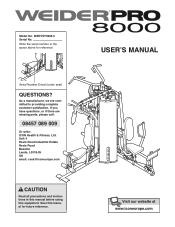
... the serial number in this manual before using this manual for reference. Serial Number Decal (under seat) QUESTIONS? Unit 4 Revie Road Industrial Estate Revie Road Beeston Leeds, LS118JG UK email: [email protected] CAUTION Read all precautions and instructions in the space above for future reference. USERʼS MANUAL As a manufacturer, we are missing parts, please call: 08457 089 009 Or write: ICON Health & Fitness, Ltd...
... the serial number in this manual before using this manual for reference. Serial Number Decal (under seat) QUESTIONS? Unit 4 Revie Road Industrial Estate Revie Road Beeston Leeds, LS118JG UK email: [email protected] CAUTION Read all precautions and instructions in the space above for future reference. USERʼS MANUAL As a manufacturer, we are missing parts, please call: 08457 089 009 Or write: ICON Health & Fitness, Ltd...

Uk Manual
Page 2
... has been placed on the front cover of this manual to order a free replacement decal. Remove the PART IDENTIFICATION CHART and PART LIST/EXPLODED DRAWING before beginning assembly. TABLE OF CONTENTS WARNING DECAL PLACEMENT 2 IMPORTANT PRECAUTIONS 3 BEFORE YOU BEGIN 4 ASSEMBLY 5 ADJUSTMENTS 25 WEIGHT RESISTANCE CHART 27 CABLE DIAGRAMS 28 MAINTENANCE 30 EXERCISE GUIDELINES 31 ORDERING REPLACEMENT PARTS Back Cover Note: A PART IDENTIFICATION CHART and a PART LIST/EXPLODED DRAWING are attached in the location shown. 2 Apply the decal in...
... has been placed on the front cover of this manual to order a free replacement decal. Remove the PART IDENTIFICATION CHART and PART LIST/EXPLODED DRAWING before beginning assembly. TABLE OF CONTENTS WARNING DECAL PLACEMENT 2 IMPORTANT PRECAUTIONS 3 BEFORE YOU BEGIN 4 ASSEMBLY 5 ADJUSTMENTS 25 WEIGHT RESISTANCE CHART 27 CABLE DIAGRAMS 28 MAINTENANCE 30 EXERCISE GUIDELINES 31 ORDERING REPLACEMENT PARTS Back Cover Note: A PART IDENTIFICATION CHART and a PART LIST/EXPLODED DRAWING are attached in the location shown. 2 Apply the decal in...
Uk Manual
Page 3
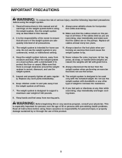
... weight system on the pulleys. Keep the weight system indoors, away from moving parts. the weights will fall with pre-existing health problems. Read all instructions in any exercise program, consult your physician. The weight system is enough clearance around the weight system to increase the resistance. 15. WARNING: Before beginning this manual. 2. Make sure that all users of the weight system are raised; Replace any time while exercising, stop...
... weight system on the pulleys. Keep the weight system indoors, away from moving parts. the weights will fall with pre-existing health problems. Read all instructions in any exercise program, consult your physician. The weight system is enough clearance around the weight system to increase the resistance. 15. WARNING: Before beginning this manual. 2. Make sure that all users of the weight system are raised; Replace any time while exercising, stop...
Uk Manual
Page 4
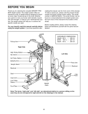
... you to the weight system (see the front cover of this manual. The serial number can be found on a decal attached to achieve the specific results you for the location of the body. Before reading further, please review the drawing below and familiarize yourself with the parts that are determined relative to right and left on the seat; Pull-up Arm ASSEMBLED DIMENSIONS: Height: 82...
... you to the weight system (see the front cover of this manual. The serial number can be found on a decal attached to achieve the specific results you for the location of the body. Before reading further, please review the drawing below and familiarize yourself with the parts that are determined relative to right and left on the seat; Pull-up Arm ASSEMBLED DIMENSIONS: Height: 82...
Uk Manual
Page 5
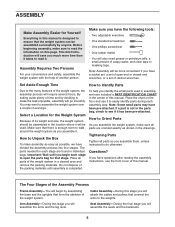
... stage you identify the small parts used . Assembly Requires Two Persons For your convenience and safety, assemble the weight system with the help you will attach the cables and pulleys that form the skeleton of the weight system. Make sure you will require several hours. Set Aside Enough Time How to Identify Parts Due to walk around the weight system as shown in the...
... stage you identify the small parts used . Assembly Requires Two Persons For your convenience and safety, assemble the weight system with the help you will attach the cables and pulleys that form the skeleton of the weight system. Make sure you will require several hours. Set Aside Enough Time How to Identify Parts Due to walk around the weight system as shown in the...
Uk Manual
Page 12
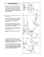
... Locknut (114). Remove the M10 x 45mm Button Bolt (105) from a Press Arm (14). Attach the Press Arm (14) to the Leg Press Frame (12) with two M8 x 70mm Bolts (97) and two M8 Nylon Locknuts (115). Do not overtighten the Locknut; Attach the Press Frame to pivot easily. Do not overtighten the Locknut; Tighten the M10 Nylon Locknut (114) used above. the Leg Press Frame must be...
... Locknut (114). Remove the M10 x 45mm Button Bolt (105) from a Press Arm (14). Attach the Press Arm (14) to the Leg Press Frame (12) with two M8 x 70mm Bolts (97) and two M8 Nylon Locknuts (115). Do not overtighten the Locknut; Attach the Press Frame to pivot easily. Do not overtighten the Locknut; Tighten the M10 Nylon Locknut (114) used above. the Leg Press Frame must be...
Uk Manual
Page 13
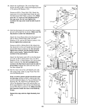
... a Top and Bottom Arm Bushing (59, 45). Attach the Dip Assist Latch (67) to the Right Seat Frame (9) with an M4 x 16mm Self-tapping Screw 114 (113) and an M4 Washer (131). the Dip Assist Latch must be able to pivot easily. Repeat this step. Hold the Dip Assist (21) around the Rear Upright (6) and Left Upright (5) as shown. Note...
... a Top and Bottom Arm Bushing (59, 45). Attach the Dip Assist Latch (67) to the Right Seat Frame (9) with an M4 x 16mm Self-tapping Screw 114 (113) and an M4 Washer (131). the Dip Assist Latch must be able to pivot easily. Repeat this step. Hold the Dip Assist (21) around the Rear Upright (6) and Left Upright (5) as shown. Note...
Uk Manual
Page 20
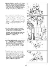
... Long Weight Tube (36). Grease the shoulder of the Long 54 Weight Tube (36). Route the Right Stack Cable (68) down through 53 the Right Top Frame (7) and over a 90mm Pulley (39). Set an M12 Washer (129) on top of an M8 x 86mm Shoulder Bolt (86). 52. ented to hold the Cable in the groove of the Bolt. 56. Tighten the...
... Long Weight Tube (36). Grease the shoulder of the Long 54 Weight Tube (36). Route the Right Stack Cable (68) down through 53 the Right Top Frame (7) and over a 90mm Pulley (39). Set an M12 Washer (129) on top of an M8 x 86mm Shoulder Bolt (86). 52. ented to hold the Cable in the groove of the Bolt. 56. Tighten the...
Uk Manual
Page 21
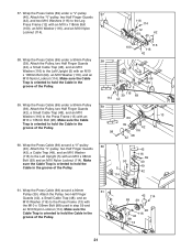
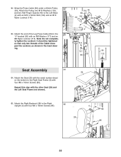
Wrap the Press Cable (69) under a 90mm Pulley (39). Wrap the Press Cable (69) under a 90mm Pulley (39). Attach the "V"-pulley, two Half Finger Guards (42), a Cable Trap (49), and an M10 Washer (116) to the Left Upright (5) with the M10 x 135mm Bolt (98) used in step 59 and an M10 Nylon Locknut (114). Make sure the Cable Trap is oriented to hold the Cable in...
Wrap the Press Cable (69) under a 90mm Pulley (39). Wrap the Press Cable (69) under a 90mm Pulley (39). Attach the "V"-pulley, two Half Finger Guards (42), a Cable Trap (49), and an M10 Washer (116) to the Left Upright (5) with the M10 x 135mm Bolt (98) used in step 59 and an M10 Nylon Locknut (114). Make sure the Cable Trap is oriented to hold the Cable in...
Uk Manual
Page 22
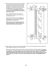
... tighten the Locknut; Repeat this step with an M8 Washer (117) and an M8 Nylon Locknut (115). it should be tightened so that only two threads of the Leg Press Cable (69) to the Right Seat Frame (9) with an M10 x 52mm Bolt (102) and an M10 Nylon Locknut (114). 63. Note: Do not complete- Attach the Seat (29) with the serial number...
... tighten the Locknut; Repeat this step with an M8 Washer (117) and an M8 Nylon Locknut (115). it should be tightened so that only two threads of the Leg Press Cable (69) to the Right Seat Frame (9) with an M10 x 52mm Bolt (102) and an M10 Nylon Locknut (114). 63. Note: Do not complete- Attach the Seat (29) with the serial number...
Uk Manual
Page 24
.... See the CABLE DIAGRAMS on pages 28 and 29 of the cables does not move smoothly over the pulleys. See MAINTENANCE on the following page. Attach the Left Front Shroud (not shown) in ADJUSTMENTS, beginning on page 30. 24 The use of the remaining parts will need to the Right Top Frame (7) and the Right Base (1) with five M5 x 9mm Screws (141...
.... See the CABLE DIAGRAMS on pages 28 and 29 of the cables does not move smoothly over the pulleys. See MAINTENANCE on the following page. Attach the Left Front Shroud (not shown) in ADJUSTMENTS, beginning on page 30. 24 The use of the remaining parts will need to the Right Top Frame (7) and the Right Base (1) with five M5 x 9mm Screws (141...
Uk Manual
Page 25
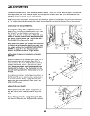
...). Adjust the length of resistance at each weight station. Replace any pulley station in the correct starting position for the exercise to see USING THE LOCK PLATE below). Use the WEIGHT RESISTANCE CHART on page 31 for each time the weight system is in the same manner. The Lat Bar (not shown), the Ab Strap (not shown), or the Handle (78) can be performed. Insert the Weight Pin...
...). Adjust the length of resistance at each weight station. Replace any pulley station in the correct starting position for the exercise to see USING THE LOCK PLATE below). Use the WEIGHT RESISTANCE CHART on page 31 for each time the weight system is in the same manner. The Lat Bar (not shown), the Ab Strap (not shown), or the Handle (78) can be performed. Insert the Weight Pin...
Uk Manual
Page 27
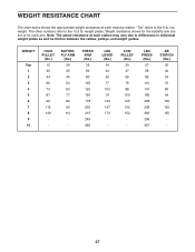
... The other numbers refer to the 6 lb. top weight. Note: The actual resistance at each exercise station. LOW PULLEY (lbs.) 29 47 59 75 88 100 120 132 152 - WEIGHT RESISTANCE CHART The chart below shows the approximate weight resistance at each station may vary due to differences in individual weight plates as well as friction between the cables, pulleys, and weight guides. Weight resistance shown for the...
... The other numbers refer to the 6 lb. top weight. Note: The actual resistance at each exercise station. LOW PULLEY (lbs.) 29 47 59 75 88 100 120 132 152 - WEIGHT RESISTANCE CHART The chart below shows the approximate weight resistance at each station may vary due to differences in individual weight plates as well as friction between the cables, pulleys, and weight guides. Weight resistance shown for the...
Uk Manual
Page 30
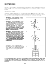
... the Pulley, and that connects the end of cable used on the weight system, can be tightened. MAINTENANCE Make sure all parts are overtightened, the top weight will be replaced, see ORDERING REPLACEMENT PARTS on the back cover of the weight stack. Tighten the M8 Nylon Locknut 1 (115) that the Cable and Pulley move smoothly. • See drawing 2. Remove the M10 Nylon Locknut 2 (114) and the M10 x 52mm Bolt (102...
... the Pulley, and that connects the end of cable used on the weight system, can be tightened. MAINTENANCE Make sure all parts are overtightened, the top weight will be replaced, see ORDERING REPLACEMENT PARTS on the back cover of the weight stack. Tighten the M8 Nylon Locknut 1 (115) that the Cable and Pulley move smoothly. • See drawing 2. Remove the M10 Nylon Locknut 2 (114) and the M10 x 52mm Bolt (102...
Uk Manual
Page 31
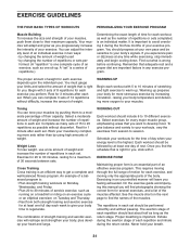
... their capacity. If you . You must gauge your limits and select the amount of your bodyʼs signals. Exercising in each week to give balance and variety to your workouts, vary the exercises from both strength training and aerobic exercise for 3 minutes after each exercise depends upon the individual user. Rest for at your heart and lungs. Weight Loss To lose weight, use a low...
... their capacity. If you . You must gauge your limits and select the amount of your bodyʼs signals. Exercising in each week to give balance and variety to your workouts, vary the exercises from both strength training and aerobic exercise for 3 minutes after each exercise depends upon the individual user. Rest for at your heart and lungs. Weight Loss To lose weight, use a low...
Uk Manual
Page 32
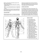
... exercise a regular and enjoyable part of your everyday life. Gluteus Maximus (buttocks) W. List the date, the exercises performed, the resistance used to 10 minutes of stretching. Hamstring (back of calf) L. Soleus (front of leg) X. Record your weight and key body measurements at the end of each workout is to increase flexibility. Rest for a short period of time after each set for a toning work...
... exercise a regular and enjoyable part of your everyday life. Gluteus Maximus (buttocks) W. List the date, the exercises performed, the resistance used to 10 minutes of stretching. Hamstring (back of calf) L. Soleus (front of leg) X. Record your weight and key body measurements at the end of each workout is to increase flexibility. Rest for a short period of time after each set for a toning work...
Uk Manual
Page 37
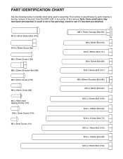
... x 9mm Screw (141) M8 x 75mm Carriage Bolt (84) M8 x 80mm Bolt (94) M10 x 80mm Bolt (111) M8 x 83mm Bolt (89) M10 x 85mm Bolt (107) M8 x 86mm Shoulder Bolt (86) M10 x 86mm Bolt (92) M10 x 103mm Bolt (106) M10 x 108mm Bolt (99) M10 x 110mm Bolt (73) M10 x 118mm Bolt (100) M10 x 135mm Bolt (98) M10 x 155mm Bolt (130) If a part is the key number of this manual. PART IDENTIFICATION CHART See...
... x 9mm Screw (141) M8 x 75mm Carriage Bolt (84) M8 x 80mm Bolt (94) M10 x 80mm Bolt (111) M8 x 83mm Bolt (89) M10 x 85mm Bolt (107) M8 x 86mm Shoulder Bolt (86) M10 x 86mm Bolt (92) M10 x 103mm Bolt (106) M10 x 108mm Bolt (99) M10 x 110mm Bolt (73) M10 x 118mm Bolt (100) M10 x 135mm Bolt (98) M10 x 155mm Bolt (130) If a part is the key number of this manual. PART IDENTIFICATION CHART See...
Uk Manual
Page 38
... Arm Cap 25mm Outer Cap Cross Brace Weight Bumper Weight Tube Bumper Dip Assist Latch Right Stack Cable Press Cable Leg Lever Cable Lat Cable Ab Cable M10 x 110mm Bolt 40mm Spacer 12mm Spacer Leg Bumper 19mm Spacer Handle Large Foam Pad Lock Plate Left Base Bushing M10 x 38mm Screw Leg Pin M8 x 75mm Carriage Bolt M6 x 16mm Screw M8 x 86mm Shoulder Bolt M8 x 69mm Shoulder Bolt M8 x 22mm Shoulder Bolt M8 x 83mm Bolt...
... Arm Cap 25mm Outer Cap Cross Brace Weight Bumper Weight Tube Bumper Dip Assist Latch Right Stack Cable Press Cable Leg Lever Cable Lat Cable Ab Cable M10 x 110mm Bolt 40mm Spacer 12mm Spacer Leg Bumper 19mm Spacer Handle Large Foam Pad Lock Plate Left Base Bushing M10 x 38mm Screw Leg Pin M8 x 75mm Carriage Bolt M6 x 16mm Screw M8 x 86mm Shoulder Bolt M8 x 69mm Shoulder Bolt M8 x 22mm Shoulder Bolt M8 x 83mm Bolt...
Uk Manual
Page 39
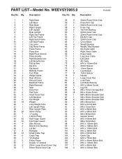
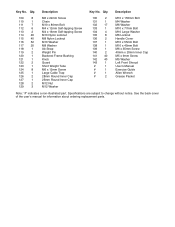
... 40 142 40 143 1 # 1 # 1 # 1 # 2 M10 x 155mm Bolt M4 Washer M6 Washer M10 x 77mm Bolt M10 Large Washer M6 Locknut Handle Cover M10 x 55mm Bolt M10 x 45mm Bolt M6 x 35mm Screw 40mm x 20mm Inner Cap M5 x 9mm Screw M5 Washer Left Front Shroud Userʼs Manual Exercise Guide Allen Wrench Grease Packet Note: "#" indicates a non-illustrated part. Description Key No. Specifications are subject to change without notice.
... 40 142 40 143 1 # 1 # 1 # 1 # 2 M10 x 155mm Bolt M4 Washer M6 Washer M10 x 77mm Bolt M10 Large Washer M6 Locknut Handle Cover M10 x 55mm Bolt M10 x 45mm Bolt M6 x 35mm Screw 40mm x 20mm Inner Cap M5 x 9mm Screw M5 Washer Left Front Shroud Userʼs Manual Exercise Guide Allen Wrench Grease Packet Note: "#" indicates a non-illustrated part. Description Key No. Specifications are subject to change without notice.
Uk Manual
Page 44
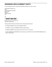
... MODEL NUMBER of the product (WEEVSY3965.0) • the NAME of the product (WEIDER PRO 8000 weight system) • the SERIAL NUMBER of the product (see the front cover of this manual) • the KEY NUMBER and DESCRIPTION of the part(s) (see the PART LIST and EXPLODED DRAWING in the centre of this manual) Part No. 233300 R1105A Printed in China © 2005 ICON IP, Inc. office, or write: ICON Health & Fitness...
... MODEL NUMBER of the product (WEEVSY3965.0) • the NAME of the product (WEIDER PRO 8000 weight system) • the SERIAL NUMBER of the product (see the front cover of this manual) • the KEY NUMBER and DESCRIPTION of the part(s) (see the PART LIST and EXPLODED DRAWING in the centre of this manual) Part No. 233300 R1105A Printed in China © 2005 ICON IP, Inc. office, or write: ICON Health & Fitness...


