
English Manual
Page 2
Remove the PART IDENTIFICATION CHART and the PART LIST/EXPLODED DRAWING before beginning assembly. 2 TABLE OF CONTENTS IMPORTANT PRECAUTIONS 3 BEFORE YOU BEGIN 4 ASSEMBLY 5 ADJUSTMENTS 21 WEIGHT RESISTANCE CHART 23 CABLE DIAGRAM 24 EXERCISE GUIDELINES 26 ORDERING REPLACEMENT PARTS Back Cover FULL 90 DAY WARRANTY Back Cover Note: A PART IDENTIFICATION CHART and a PART LIST/EXPLODED DRAWING are attached in the center of this manual.
Remove the PART IDENTIFICATION CHART and the PART LIST/EXPLODED DRAWING before beginning assembly. 2 TABLE OF CONTENTS IMPORTANT PRECAUTIONS 3 BEFORE YOU BEGIN 4 ASSEMBLY 5 ADJUSTMENTS 21 WEIGHT RESISTANCE CHART 23 CABLE DIAGRAM 24 EXERCISE GUIDELINES 26 ORDERING REPLACEMENT PARTS Back Cover FULL 90 DAY WARRANTY Back Cover Note: A PART IDENTIFICATION CHART and a PART LIST/EXPLODED DRAWING are attached in the center of this manual.
English Manual
Page 3
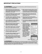
.... 5. The warning decals shown here have been placed on the pulleys at any time while exercising, stop immediately and make sure that could cause the weight system to tip. 3. If a decal is intended for personal injury or property damage sustained by or through Saturday, 7 a.m. Place the decal on the foot plate... feel pain or dizziness at all parts are raised; Do not use of 12 and pets away from moving parts. 8. Make sure all times. The weight system is used. Never release the press arm, butterfly arms, leg lever, leg press base, lat bar, ab strap, or handle while...
.... 5. The warning decals shown here have been placed on the pulleys at any time while exercising, stop immediately and make sure that could cause the weight system to tip. 3. If a decal is intended for personal injury or property damage sustained by or through Saturday, 7 a.m. Place the decal on the foot plate... feel pain or dizziness at all parts are raised; Do not use of 12 and pets away from moving parts. 8. Make sure all times. The weight system is used. Never release the press arm, butterfly arms, leg lever, leg press base, lat bar, ab strap, or handle while...
English Manual
Page 4
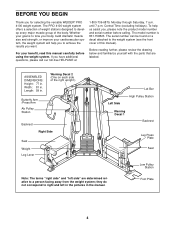
...left in the pictures in . The PRO 4100 weight system offers a selection of weight stations designed to the weight system (see the front cover of this manual carefully before calling. Length: 59 in . If you for selecting the versatile WEIDER® PRO 4100 weight system. they do not correspond to ...side" are labeled. ASSEMBLED DIMENSIONS: Height: 77 in the manual. To help you to a person facing away from the weight system; Before reading further, please review the drawing below and familiarize yourself with the parts that are determined relative to achieve ...
...left in the pictures in . The PRO 4100 weight system offers a selection of weight stations designed to the weight system (see the front cover of this manual carefully before calling. Length: 59 in . If you for selecting the versatile WEIDER® PRO 4100 weight system. they do not correspond to ...side" are labeled. ASSEMBLED DIMENSIONS: Height: 77 in the manual. To help you to a person facing away from the weight system; Before reading further, please review the drawing below and familiarize yourself with the parts that are determined relative to achieve ...
English Manual
Page 5
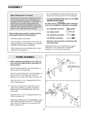
...carefully read and understand the information in a cleared area and remove the packing materials. Before beginning assembly, be more convenient if you assemble the weight system, make sure all parts in the box above. Attach the Center Base (67) to the Right Base (1) and Center Base (67...; one standard screwdriver • one Phillips screwdriver • lubricant, such as shown in this manual is important to realize that the versatile weight system has many parts and that the assembly process will take time. FRAME ASSEMBLY 1. Most people find that by anyone. Attach the Left ...
...carefully read and understand the information in a cleared area and remove the packing materials. Before beginning assembly, be more convenient if you assemble the weight system, make sure all parts in the box above. Attach the Center Base (67) to the Right Base (1) and Center Base (67...; one standard screwdriver • one Phillips screwdriver • lubricant, such as shown in this manual is important to realize that the versatile weight system has many parts and that the assembly process will take time. FRAME ASSEMBLY 1. Most people find that by anyone. Attach the Left ...

English Manual
Page 7
... 26 83 71 26 67 26 26 60 7 Do not tighten the 5/16" Nylon Locknuts (71) yet. 7. Set two Weight Bumpers (83) over the indicated holes in the Center Base (67). Attach the Weight Guides to the Left Upright (7) with two 5/16" x 2 1/2" Carriage Bolts (57) and two 5/16" Nylon Locknuts (71).... Frame (29) to the Right Upright (6) with two 5/16" x 3 1/4" Bolts (59), two 5/16" Washers (26), and two 5/16" Nylon Locknuts (71). Insert the two Weight Guides (20) into the end of the Left Seat Frame (29). 5. Attach the Right Seat Frame (5) to the Right Leg (73) with two 5/16" x 3 1/4" Bolts...
... 26 83 71 26 67 26 26 60 7 Do not tighten the 5/16" Nylon Locknuts (71) yet. 7. Set two Weight Bumpers (83) over the indicated holes in the Center Base (67). Attach the Weight Guides to the Left Upright (7) with two 5/16" x 2 1/2" Carriage Bolts (57) and two 5/16" Nylon Locknuts (71).... Frame (29) to the Right Upright (6) with two 5/16" x 3 1/4" Bolts (59), two 5/16" Washers (26), and two 5/16" Nylon Locknuts (71). Insert the two Weight Guides (20) into the end of the Left Seat Frame (29). 5. Attach the Right Seat Frame (5) to the Right Leg (73) with two 5/16" x 3 1/4" Bolts...
English Manual
Page 8
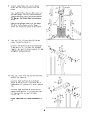
...side shown. Do not tighten the Locknuts yet. 9 22 3 59 21 71 22 71 7 10. Press a 2" x 2 1/2" Inner Cap (22) into the ends of Weights (72). Attach the Right Top Frame (8) to the Left Upright (7) with two 5/16" x 2 3/4" Bolts (60), two 5/16" Washers (26), and two 5/16" ... (3) with two 5/16" x 3 1/4" Bolts (59), a Support Plate (21), and two 5/16" Nylon Locknuts (71). Be sure the Weight Tube is oriented as shown. Slide the eight Weights (72) onto the Weight 8 Guides (20) with two 5/16" x 3 1/4" Bolts (59), a Support Plate (21), and two 5/16" Nylon Locknuts (71). ...
...side shown. Do not tighten the Locknuts yet. 9 22 3 59 21 71 22 71 7 10. Press a 2" x 2 1/2" Inner Cap (22) into the ends of Weights (72). Attach the Right Top Frame (8) to the Left Upright (7) with two 5/16" x 2 3/4" Bolts (60), two 5/16" Washers (26), and two 5/16" ... (3) with two 5/16" x 3 1/4" Bolts (59), a Support Plate (21), and two 5/16" Nylon Locknuts (71). Be sure the Weight Tube is oriented as shown. Slide the eight Weights (72) onto the Weight 8 Guides (20) with two 5/16" x 3 1/4" Bolts (59), a Support Plate (21), and two 5/16" Nylon Locknuts (71). ...
English Manual
Page 9
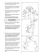
11. Slide the Center Top Frame onto the Weight Guides (20). Lubricate a 3/8" x 3" Bolt (61) with the Bolt and a 3/8" Nylon Locknut (70). Do not overtighten the Locknut; the Butterfly Frame must be able to the ... 71 44 71 14 60 26 71 8 71 26 60 26 20 3 12 8 22 41 70 Lubricate 6 61 13. ARM ASSEMBLY 12. Press the two Weight Guide Bushings (44) into the end of the Right Butterfly Arm (11). Tighten all of the 5/16" Nylon Locknuts (71) used later.
11. Slide the Center Top Frame onto the Weight Guides (20). Lubricate a 3/8" x 3" Bolt (61) with the Bolt and a 3/8" Nylon Locknut (70). Do not overtighten the Locknut; the Butterfly Frame must be able to the ... 71 44 71 14 60 26 71 8 71 26 60 26 20 3 12 8 22 41 70 Lubricate 6 61 13. ARM ASSEMBLY 12. Press the two Weight Guide Bushings (44) into the end of the Right Butterfly Arm (11). Tighten all of the 5/16" Nylon Locknuts (71) used later.
English Manual
Page 11
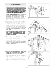
.... 19. IMPORTANT: While assembling the cables, do not over tighten the locknuts attaching the pulleys; Attach the Pulley and a Cable Trap (91) inside of the weight system, with a 3/8" x 1 3/4" Bolt (66) and a 3/8" Nylon Locknut (70). 70 14 38 45 66 11 the pulleys must be necessary to turn freely...
.... 19. IMPORTANT: While assembling the cables, do not over tighten the locknuts attaching the pulleys; Attach the Pulley and a Cable Trap (91) inside of the weight system, with a 3/8" x 1 3/4" Bolt (66) and a 3/8" Nylon Locknut (70). 70 14 38 45 66 11 the pulleys must be necessary to turn freely...
English Manual
Page 12
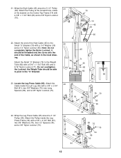
... 34 95 30 12 Note: Do not completely tighten the Nylon Locknut; Wrap the Leg Press Cable (95) around a 3 1/2" Pulley 21 (38). 21. the Weight Tube should be able to the Small "U"-Bracket (79) with a 1/4" Washer (35) and a 1/4" Nylon Locknut (65). Attach the Small "U"-Bracket (79) to the... Weight Tube (82) with a 3/8" x 1 3/4" Bolt (66) and a 3/8" Nylon Locknut (70). 22. Attach the end of the Cable, as shown in the "U"-Bracket. 22 79 69...
... 34 95 30 12 Note: Do not completely tighten the Nylon Locknut; Wrap the Leg Press Cable (95) around a 3 1/2" Pulley 21 (38). 21. the Weight Tube should be able to the Small "U"-Bracket (79) with a 1/4" Washer (35) and a 1/4" Nylon Locknut (65). Attach the Small "U"-Bracket (79) to the... Weight Tube (82) with a 3/8" x 1 3/4" Bolt (66) and a 3/8" Nylon Locknut (70). 22. Attach the end of the Cable, as shown in the "U"-Bracket. 22 79 69...
English Manual
Page 20
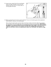
.... 53 68 9 53 54. IMPORTANT: If the cables are not properly routed, they may be explained in the cables, you will be damaged when heavy weight is any slack in ADJUSTMENTS, starting on pages 24 and 25 of the cables does not move smoothly over the pulleys. Attach the tether on...
.... 53 68 9 53 54. IMPORTANT: If the cables are not properly routed, they may be explained in the cables, you will be damaged when heavy weight is any slack in ADJUSTMENTS, starting on pages 24 and 25 of the cables does not move smoothly over the pulleys. Attach the tether on...
English Manual
Page 21
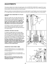
...Holes 10 21 Replace any exercises. The Handle (not shown) and Ab Strap (not shown) can be attached in the same manner. The weight setting of the weight stack can be attached between the Lat Bar and the High Cable so the Lat Bar is used. Make sure that the Locking Pins... increments of holes before performing any worn parts immediately. Note: Due to the cables and pulleys, the actual amount of resistance at each time the weight system is in the Right Upright (6). Do not use the Butterfly Arms (10, 11) as butterfly arms, insert the Locking Pins (53) into the ...
...Holes 10 21 Replace any exercises. The Handle (not shown) and Ab Strap (not shown) can be attached in the same manner. The weight setting of the weight stack can be attached between the Lat Bar and the High Cable so the Lat Bar is used. Make sure that the Locking Pins... increments of holes before performing any worn parts immediately. Note: Due to the cables and pulleys, the actual amount of resistance at each time the weight system is in the Right Upright (6). Do not use the Butterfly Arms (10, 11) as butterfly arms, insert the Locking Pins (53) into the ...
English Manual
Page 22
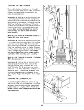
... remove the 3 1/2" Pulley (38) from the "U"-Bracket, or remove the Small "U"-Bracket from the Weight Tube (not shown). Move the 3 1/2" Pulley (38) in the other "U"-Bracket (85) in the cables before ...resistance is first used on the weight system, can be removed by moving the 3 1/2" Pulley (38) and the Cable Trap (91) to the higher... Trap to the desired position and secure it is felt, the cables should be lifted off the weight stack. To do this, you may need to the locked position around the Leg Press Frame. Move...
... remove the 3 1/2" Pulley (38) from the "U"-Bracket, or remove the Small "U"-Bracket from the Weight Tube (not shown). Move the 3 1/2" Pulley (38) in the other "U"-Bracket (85) in the cables before ...resistance is first used on the weight system, can be removed by moving the 3 1/2" Pulley (38) and the Cable Trap (91) to the higher... Trap to the desired position and secure it is felt, the cables should be lifted off the weight stack. To do this, you may need to the locked position around the Leg Press Frame. Move...
English Manual
Page 23
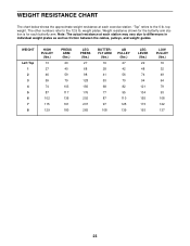
... well as friction between the cables, pulleys, and weight guides. Note: The actual resistance at each butterfly arm. weight plates. "Top" refers to the 6 lb. WEIGHT RESISTANCE CHART The chart below shows the approximate weight resistance at each station may vary due to the 12.5 lb. top weight. WEIGHT Left Top 1 2 3 4 5 6 7 8 HIGH PULLEY (lbs.) 13 27...
... well as friction between the cables, pulleys, and weight guides. Note: The actual resistance at each butterfly arm. weight plates. "Top" refers to the 6 lb. WEIGHT RESISTANCE CHART The chart below shows the approximate weight resistance at each station may vary due to the 12.5 lb. top weight. WEIGHT Left Top 1 2 3 4 5 6 7 8 HIGH PULLEY (lbs.) 13 27...
English Manual
Page 24
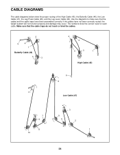
... cable diagrams below show the correct route for each cable. Make sure that the cables and the cable traps have not been correctly routed, the weight system will not function properly and damage may occur.
... cable diagrams below show the correct route for each cable. Make sure that the cables and the cable traps have not been correctly routed, the weight system will not function properly and damage may occur.
English Manual
Page 26
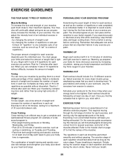
... capacity. Rest for 3 minutes after each set . Toning You can complete 3 sets of 12 repetitions without discomfort. Select a moderate amount of weight and increase the number of repetitions in each set . Rest for more oxygen to avoid overdoing it . An example of a balanced program is ... pain or dizziness at least one sit-up . If you progressively increase the intensity of your workouts, vary the exercises from both weight training and aerobic exercise for each set " is important. Remember that is an essential part of an effective exercise program. This requires...
... capacity. Rest for 3 minutes after each set . Toning You can complete 3 sets of 12 repetitions without discomfort. Select a moderate amount of weight and increase the number of repetitions in each set . Rest for more oxygen to avoid overdoing it . An example of a balanced program is ... pain or dizziness at least one sit-up . If you progressively increase the intensity of your workouts, vary the exercises from both weight training and aerobic exercise for each set " is important. Remember that is an essential part of an effective exercise program. This requires...
English Manual
Page 27
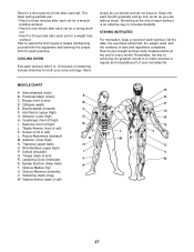
... MUSCLE CHART A. Sartorius (front of calf) K. Spinae Erectors (lower back) K T. Rest for a short period of time after each set for a weight loss workout. The ideal resting periods are: • Rest for three minutes after each set for a muscle building workout. • Rest for one minute... do not bounce. STAYING MOTIVATED For motivation, keep a record of sets and repetitions completed. list the date, the exercises performed, the weight used, and the numbers of each workout with the equipment and learning the proper form for a toning work- Record your arms and legs...
... MUSCLE CHART A. Sartorius (front of calf) K. Spinae Erectors (lower back) K T. Rest for a short period of time after each set for a weight loss workout. The ideal resting periods are: • Rest for three minutes after each set for a muscle building workout. • Rest for one minute... do not bounce. STAYING MOTIVATED For motivation, keep a record of sets and repetitions completed. list the date, the exercises performed, the weight used, and the numbers of each workout with the equipment and learning the proper form for a toning work- Record your arms and legs...
English Manual
Page 30
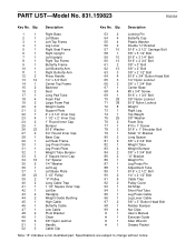
...3/4" Bolt 14 1 Center Top Frame 15 2 Backrest 16 2 Seat 17 1 Long Pad Tube 18 4 Foam Pad 19 2 Large Foam Pad 20 2 Weight Guide 21 2 Support Plate 22 7 2" x 2 1/2" Inner Cap 23 4 1 1/2" x 2" Inner Cap 24 2 1" Round Inner Cap 25 1...1" Screw 78 3 5/16" x 1" Shoulder Bolt 79 1 Small "U"-Bracket 80 2 Long Spacer 81 9 3/8" x 2 3/4" Bolt 82 1 Weight Tube 83 2 Weight Bumper 84 2 3/8" x 3 3/4" Bolt 85 2 "U"-Bracket 86 1 Weight Pin 87 1 Leg Press Pin 88 1 Adjustment Tube 89 1 5/16" x 2 1/2" Bolt 90 2 1/4" x 2 1/2" Bolt 91 6 Cable...
...3/4" Bolt 14 1 Center Top Frame 15 2 Backrest 16 2 Seat 17 1 Long Pad Tube 18 4 Foam Pad 19 2 Large Foam Pad 20 2 Weight Guide 21 2 Support Plate 22 7 2" x 2 1/2" Inner Cap 23 4 1 1/2" x 2" Inner Cap 24 2 1" Round Inner Cap 25 1...1" Screw 78 3 5/16" x 1" Shoulder Bolt 79 1 Small "U"-Bracket 80 2 Long Spacer 81 9 3/8" x 2 3/4" Bolt 82 1 Weight Tube 83 2 Weight Bumper 84 2 3/8" x 3 3/4" Bolt 85 2 "U"-Bracket 86 1 Weight Pin 87 1 Leg Press Pin 88 1 Adjustment Tube 89 1 5/16" x 2 1/2" Bolt 90 2 1/4" x 2 1/2" Bolt 91 6 Cable...
English Manual
Page 32
...which vary from the date of charge. Sears, Roebuck and Co., Dept. 817WA, Hoffman Estates, IL 60179 Part No. 194159 R0203A Printed in this Sears Weight System Exerciser, contact the nearest Sears Service Center throughout the United States and Sears will repair or replace the... Weight System Exerciser, free of purchase, if failure occurs due to state. This warranty does not apply when the Weight System Exerciser is used commercially or for rental purposes. FULL 90 DAY WARRANTY For 90 ...
...which vary from the date of charge. Sears, Roebuck and Co., Dept. 817WA, Hoffman Estates, IL 60179 Part No. 194159 R0203A Printed in this Sears Weight System Exerciser, contact the nearest Sears Service Center throughout the United States and Sears will repair or replace the... Weight System Exerciser, free of purchase, if failure occurs due to state. This warranty does not apply when the Weight System Exerciser is used commercially or for rental purposes. FULL 90 DAY WARRANTY For 90 ...


