

English Manual
Page 2
Remove the PART IDENTIFICATION CHART and the PART LIST/EXPLODED DRAWING before beginning assembly. WEIDER is a registered trademark of this manual. TABLE OF CONTENTS IMPORTANT PRECAUTIONS 3 BEFORE YOU BEGIN 4 ASSEMBLY 5 ADJUSTMENTS 21 WEIGHT RESISTANCE CHART 23 TROUBLESHOOTING 24 CABLE DIAGRAMS 25 ORDERING REPLACEMENT PARTS Back Cover LIMITED WARRANTY Back Cover Note: A PART IDENTIFICATION CHART and a PART LIST/EXPLODED DRAWING are attached in the center of ICON Health & Fitness, Inc. 2
Remove the PART IDENTIFICATION CHART and the PART LIST/EXPLODED DRAWING before beginning assembly. WEIDER is a registered trademark of this manual. TABLE OF CONTENTS IMPORTANT PRECAUTIONS 3 BEFORE YOU BEGIN 4 ASSEMBLY 5 ADJUSTMENTS 21 WEIGHT RESISTANCE CHART 23 TROUBLESHOOTING 24 CABLE DIAGRAMS 25 ORDERING REPLACEMENT PARTS Back Cover LIMITED WARRANTY Back Cover Note: A PART IDENTIFICATION CHART and a PART LIST/EXPLODED DRAWING are attached in the center of ICON Health & Fitness, Inc. 2

English Manual
Page 3
... decal is especially important for personal injury or property damage sustained by or through Friday, 6 a.m. Keep hands and feet away from the weight system at 1-800-999-3756, Monday through the use of this or any time while exercising, stop immediately and make sure that does not... you are raised. Never release the press arm, butterfly arms, leg lever, leg press, lat bar, ab strap, or nylon strap while weights are exercising, stop immediately and begin cooling down. 14. IMPORTANT PRECAUTIONS WARNING: To reduce the risk of serious injury, read the following important ...
... decal is especially important for personal injury or property damage sustained by or through Friday, 6 a.m. Keep hands and feet away from the weight system at 1-800-999-3756, Monday through the use of this or any time while exercising, stop immediately and make sure that does not... you are raised. Never release the press arm, butterfly arms, leg lever, leg press, lat bar, ab strap, or nylon strap while weights are exercising, stop immediately and begin cooling down. 14. IMPORTANT PRECAUTIONS WARNING: To reduce the risk of serious injury, read the following important ...

English Manual
Page 4
If you for selecting the versatile WEIDER® PRO 3770 weight system. Length: 91.5 in . The serial number ...to achieve the specific results you , please note the product model number and serial number before using the weight system. BEFORE YOU BEGIN Thank you have additional questions, please call our Customer Service Department toll-free at... Curl Pad Leg Lever Low Pulley Station Foot Plate 4 until 6 p.m. The weight system offers a selection of weight stations designed to the weight system (see the front cover of the body. Before reading further, please review...
If you for selecting the versatile WEIDER® PRO 3770 weight system. Length: 91.5 in . The serial number ...to achieve the specific results you , please note the product model number and serial number before using the weight system. BEFORE YOU BEGIN Thank you have additional questions, please call our Customer Service Department toll-free at... Curl Pad Leg Lever Low Pulley Station Foot Plate 4 until 6 p.m. The weight system offers a selection of weight stations designed to the weight system (see the front cover of the body. Before reading further, please review...

English Manual
Page 5
...and the leg levers. Important: Wait until you assemble them, unless instructed to do otherwise. Note: Assembly will be used in the center of the weight system, the assembly process will save you much more convenient if you identify the small parts used . How to Orient Parts As you assemble the... person. Mountain Time. Set Aside Enough Time Due to open -end or closed-end wrenches, or a set of open the parts bag for the Weight System Because of evenings. You may have divided the assembly process into four stages. Place all parts as shown in the drawings. Place the chart...
...and the leg levers. Important: Wait until you assemble them, unless instructed to do otherwise. Note: Assembly will be used in the center of the weight system, the assembly process will save you much more convenient if you identify the small parts used . How to Orient Parts As you assemble the... person. Mountain Time. Set Aside Enough Time Due to open -end or closed-end wrenches, or a set of open the parts bag for the Weight System Because of evenings. You may have divided the assembly process into four stages. Place all parts as shown in the drawings. Place the chart...

English Manual
Page 8
...drawing 12 on top of the Press Top Frame (9). Set the two Weight Bumpers (51) over the holes in the Weights are oriented so that the Weight Tube (17) goes into the end of the Weight Bumpers (51). Secure the Weight Guides to the Press Top Frame (9), as shown. 9 21 56 15...two 3/8" Nylon Locknuts (50). Press the Weight Tube Bumper (18) into each Weight (21). Do not tighten the Nylon Locknuts yet. Insert two Weight Inserts (56) into the Weight 10 Tube (17). Slide the Weight Guides (15) through the Weight Bumpers (51) and the holes in the Weights (21). 16 15 17 18 21 ...
...drawing 12 on top of the Press Top Frame (9). Set the two Weight Bumpers (51) over the holes in the Weights are oriented so that the Weight Tube (17) goes into the end of the Weight Bumpers (51). Secure the Weight Guides to the Press Top Frame (9), as shown. 9 21 56 15...two 3/8" Nylon Locknuts (50). Press the Weight Tube Bumper (18) into each Weight (21). Do not tighten the Nylon Locknuts yet. Insert two Weight Inserts (56) into the Weight 10 Tube (17). Slide the Weight Guides (15) through the Weight Bumpers (51) and the holes in the Weights (21). 16 15 17 18 21 ...

English Manual
Page 9
Secure the Weight Guides (15) to the Press Top Frame (9) with the Left Pivot Arm (not shown) and left axle. 9 35 Axle 38 33 Lubricate 85 31 38 ...
Secure the Weight Guides (15) to the Press Top Frame (9) with the Left Pivot Arm (not shown) and left axle. 9 35 Axle 38 33 Lubricate 85 31 38 ...

English Manual
Page 14
...with a 3/8" Nylon Locknut (50). 3 24 54 4 72 50 Bracket 3 50 48 62 48 24 72 66 33. 31. Be sure the Weight Cable is in the groove of the Weight Cable has a bolt, and the other end has a ball on the Butterfly Base (4) in the Leg Lever (41), up around a 3 1/2" ... (24) and two 5/8" x 1/2" Bushings (93) to the Bolt with a 3/8" x 2" Bolt (54) and a 3/8" Nylon Locknut (50). 34 72 24 54 4 50 Bracket 14 Lay the Weight Cable (72) inside the bracket on it. Wrap the Weight Cable (72) around a 3 1/2" Pulley (24), back through the hole in the Butterfly Front Leg (3). Lay the...
...with a 3/8" Nylon Locknut (50). 3 24 54 4 72 50 Bracket 3 50 48 62 48 24 72 66 33. 31. Be sure the Weight Cable is in the groove of the Weight Cable has a bolt, and the other end has a ball on the Butterfly Base (4) in the Leg Lever (41), up around a 3 1/2" ... (24) and two 5/8" x 1/2" Bushings (93) to the Bolt with a 3/8" x 2" Bolt (54) and a 3/8" Nylon Locknut (50). 34 72 24 54 4 50 Bracket 14 Lay the Weight Cable (72) inside the bracket on it. Wrap the Weight Cable (72) around a 3 1/2" Pulley (24), back through the hole in the Butterfly Front Leg (3). Lay the...

English Manual
Page 15
... (23) hanging from the Butterfly Cable (73) with a 3/8" x 4" Bolt (59), a 3/8" Flat Washer (48), and a 3/8" Nylon Jamnut (63). Note: For convenience, the weights assembled 38 in step 9 are not shown in step 23. Be sure that the Cable Trap is turned to hold the Cable in place. 72... 57 38. Attach the 3 1/2" Pulley and a Cable Trap (25) to hold the Cable in place. 73 54 25 24 72 23 50 37. Wrap the Weight Cable (72) around a 3 1/2" Pulley 35 (24). Be sure that the Cable Trap is turned to the bracket on the Butterfly Base (4) with a 3/8" x 1 3/4"...
... (23) hanging from the Butterfly Cable (73) with a 3/8" x 4" Bolt (59), a 3/8" Flat Washer (48), and a 3/8" Nylon Jamnut (63). Note: For convenience, the weights assembled 38 in step 9 are not shown in step 23. Be sure that the Cable Trap is turned to hold the Cable in place. 72... 57 38. Attach the 3 1/2" Pulley and a Cable Trap (25) to hold the Cable in place. 73 54 25 24 72 23 50 37. Wrap the Weight Cable (72) around a 3 1/2" Pulley 35 (24). Be sure that the Cable Trap is turned to the bracket on the Butterfly Base (4) with a 3/8" x 1 3/4"...

English Manual
Page 16
...) with a 3/8" x 1 3/4" Bolt (57) and a 3/8" Nylon Locknut (50). 24 50 72 57 22 41. Place a 1/2" Flat Washer (11) on the Weight Cable (72). Wrap the Weight Cable (72) around a 3 1/2" Pulley (24). Screw the bolt on the Press Top Frame (9) with a 3/8" x 2" Bolt (54) and a 3/8" Nylon Locknut ...(50) that the Cable Trap is turned to the bracket on the Weight Cable into the Weight Tube (17) a couple of the Weight 42 Tube (17). Attach the 3 1/2" Pulley between the lowest holes in the Adjustable Pulley Plates (23) hanging from the...
...) with a 3/8" x 1 3/4" Bolt (57) and a 3/8" Nylon Locknut (50). 24 50 72 57 22 41. Place a 1/2" Flat Washer (11) on the Weight Cable (72). Wrap the Weight Cable (72) around a 3 1/2" Pulley (24). Screw the bolt on the Press Top Frame (9) with a 3/8" x 2" Bolt (54) and a 3/8" Nylon Locknut ...(50) that the Cable Trap is turned to the bracket on the Weight Cable into the Weight Tube (17) a couple of the Weight 42 Tube (17). Attach the 3 1/2" Pulley between the lowest holes in the Adjustable Pulley Plates (23) hanging from the...

English Manual
Page 20
... the Leg Lever (41). IMPORTANT: If the cables are not properly installed, they may be explained in the cables, you will be damaged when heavy weight is any slack in ADJUSTMENTS, beginning on page 25 and 26 of the Pad Tube. Attach the Curl Pad (91) to remove the slack by... 49 3 57. Slide the Preacher Post (39) into each cable a few times to be sure that all parts have been properly tightened. Before using the weight system, pull each of the cables does not move smoothly over the pulleys. If one side of a Pad Tube (42). 55. See the CABLE DIAGRAMS...
... the Leg Lever (41). IMPORTANT: If the cables are not properly installed, they may be explained in the cables, you will be damaged when heavy weight is any slack in ADJUSTMENTS, beginning on page 25 and 26 of the Pad Tube. Attach the Curl Pad (91) to remove the slack by... 49 3 57. Slide the Preacher Post (39) into each cable a few times to be sure that all parts have been properly tightened. Before using the weight system, pull each of the cables does not move smoothly over the pulleys. If one side of a Pad Tube (42). 55. See the CABLE DIAGRAMS...

English Manual
Page 21
... OR AB STRAP TO THE HIGH PULLEY STATION Attach the Lat Bar (61) to see how the weight system should be reduced. Adjust the length of the Chain between the Lat Bar and the Ab Cable...(26) can be performed. If there is any slack in the correct starting position for the exercise to the Weight Cable (72) with two Cable Clips. For some exercises, the Chain (67) should be performed. IMPORTANT: ...so the Lat Bar is in the same manner. 21 72 69 81 67 26 61 The weight setting can be performed. Adjust the length of resistance at each exercise station may vary from 10...
... OR AB STRAP TO THE HIGH PULLEY STATION Attach the Lat Bar (61) to see how the weight system should be reduced. Adjust the length of the Chain between the Lat Bar and the Ab Cable...(26) can be performed. If there is any slack in the correct starting position for the exercise to the Weight Cable (72) with two Cable Clips. For some exercises, the Chain (67) should be performed. IMPORTANT: ...so the Lat Bar is in the same manner. 21 72 69 81 67 26 61 The weight setting can be performed. Adjust the length of resistance at each exercise station may vary from 10...

English Manual
Page 22
... ab pulley station with the desired set of holes in the Preacher Post. ADJUSTING THE CURL PAD Remove the Large Adjustment Knob (46) from the weight system. 47 69 81 2 12 5 91 46 39 3 22 ADJUSTING THE BACKREST To adjust a Backrest (12), loosen the Adjustment Knob (5) on the Press Upright (2) or...
... ab pulley station with the desired set of holes in the Preacher Post. ADJUSTING THE CURL PAD Remove the Large Adjustment Knob (46) from the weight system. 47 69 81 2 12 5 91 46 39 3 22 ADJUSTING THE BACKREST To adjust a Backrest (12), loosen the Adjustment Knob (5) on the Press Upright (2) or...

English Manual
Page 23
Note: The actual resistance at each weight station may vary due to differences in individual weight plates, as well as friction between the cables, pulleys, and weight guides. "Top" refers to the 10 lb. WEIGHT PLATES Top 1 2 3 4 5 6 7 8 9 10 11 12 13 14 15 16 17 18 19 PRESS ARM (lbs.) 15 ... 78 98 118 138 158 178 198 218 239 259 279 299 319 339 359 379 399 23 weight plates. top weight. WEIGHT RESISTANCE CHART This chart shows the approximate weight resistance at each weight station. The other numbers refer to the 10 lb. The butterfly arm resistance listed is the resistance...
Note: The actual resistance at each weight station may vary due to differences in individual weight plates, as well as friction between the cables, pulleys, and weight guides. "Top" refers to the 10 lb. WEIGHT PLATES Top 1 2 3 4 5 6 7 8 9 10 11 12 13 14 15 16 17 18 19 PRESS ARM (lbs.) 15 ... 78 98 118 138 158 178 198 218 239 259 279 299 319 339 359 379 399 23 weight plates. top weight. WEIGHT RESISTANCE CHART This chart shows the approximate weight resistance at each weight station. The other numbers refer to the 10 lb. The butterfly arm resistance listed is the resistance...

English Manual
Page 24
... cleaned using a damp cloth and mild non-abrasive detergent. If a cable tends to slip off the weight stack. Remove the cable and re-install it may have become twisted. The weight system can be adjusted in the cables before resistance is felt, the cables should be lifted off the ... the middle of this manner. 2 54 25 23 50 24 Do not overtighten the cables. Slack can be replaced, see ORDERING REPLACEMENT PARTS on the Weight 1 Cable (72) bolt, away from the Adjustable Pulley Plates (23). Remove either the upper or lower 3/8" Nylon Locknut (50) and 3/8" x 2" Bolt (54) from ...
... cleaned using a damp cloth and mild non-abrasive detergent. If a cable tends to slip off the weight stack. Remove the cable and re-install it may have become twisted. The weight system can be adjusted in the cables before resistance is felt, the cables should be lifted off the ... the middle of this manner. 2 54 25 23 50 24 Do not overtighten the cables. Slack can be replaced, see ORDERING REPLACEMENT PARTS on the Weight 1 Cable (72) bolt, away from the Adjustable Pulley Plates (23). Remove either the upper or lower 3/8" Nylon Locknut (50) and 3/8" x 2" Bolt (54) from ...

English Manual
Page 25
... (72). IMPORTANT: If the Cables have been assembled correctly. Use the diagrams to be sure that the Cables have not been correctly routed, the weight system will not function properly and damage may occur. The numbers show the proper routing of each Cable. Leg Press Cable (75) 6 9 10 11-Press ...
... (72). IMPORTANT: If the Cables have been assembled correctly. Use the diagrams to be sure that the Cables have not been correctly routed, the weight system will not function properly and damage may occur. The numbers show the proper routing of each Cable. Leg Press Cable (75) 6 9 10 11-Press ...

English Manual
Page 26
Weight Cable (72) 11 Cable ID 9 10 6 12-Weight Stack 8 7 5 4 2 72 47 75 73 3 1-Low Pulley 26
Weight Cable (72) 11 Cable ID 9 10 6 12-Weight Stack 8 7 5 4 2 72 47 75 73 3 1-Low Pulley 26
English Manual
Page 31
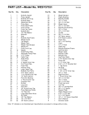
...12 2 Backrest 13 2 Seat 14 1 Butterfly Seat Frame 15 2 Weight Guide 16 1 Top Weight 17 1 Weight Tube 18 1 Weight Tube Bumper 19 1 Weight Pin 20 1 Press Front Leg 21 19 Weight 22 2 Small Pulley Plate 23 4 Adjustable Pulley Plate 24 26 ... 3" Bolt 89 3 3/8" x 2 3/4" Bolt 90 1 Press Leg Lever 91 1 Curl Pad 92 8 3/8" x 2" Carriage Bolt 93 2 5/8" x 1/2" Spacer 94 2 Support Plate 95 1 Plastic Weight Cover 96 4 5/16" x 2 3/4" Bolt 97 1 1/2" x 3/4" Spacer 98 1 3/8" x 1 1/2" Button Head Bolt # 1 User's Manual # 1 Exercise Guide Note: "#" indicates a non-...
...12 2 Backrest 13 2 Seat 14 1 Butterfly Seat Frame 15 2 Weight Guide 16 1 Top Weight 17 1 Weight Tube 18 1 Weight Tube Bumper 19 1 Weight Pin 20 1 Press Front Leg 21 19 Weight 22 2 Small Pulley Plate 23 4 Adjustable Pulley Plate 24 26 ... 3" Bolt 89 3 3/8" x 2 3/4" Bolt 90 1 Press Leg Lever 91 1 Curl Pad 92 8 3/8" x 2" Carriage Bolt 93 2 5/8" x 1/2" Spacer 94 2 Support Plate 95 1 Plastic Weight Cover 96 4 5/16" x 2 3/4" Bolt 97 1 1/2" x 3/4" Spacer 98 1 3/8" x 1 1/2" Button Head Bolt # 1 User's Manual # 1 Exercise Guide Note: "#" indicates a non-...

English Manual
Page 33
... holidays). This warranty extends only to give the following information: • The MODEL NUMBER of the product (WESY37531) • The NAME of the product (WEIDER® PRO 3770 weight system) • The SERIAL NUMBER of the product (see the front cover of this manual) • The KEY NUMBER and DESCRIPTION of the part(s) (see...
... holidays). This warranty extends only to give the following information: • The MODEL NUMBER of the product (WESY37531) • The NAME of the product (WEIDER® PRO 3770 weight system) • The SERIAL NUMBER of the product (see the front cover of this manual) • The KEY NUMBER and DESCRIPTION of the part(s) (see...


