

Canadian English Manual
Page 1
Model No. 30279.0 Serial No. CALL TOLL-FREE: 1-888-936-4266 Mon.-Fri., 8:00 until 17:00 ET (excluding holidays) OR E-MAIL US: [email protected] CAUTION Read all precautions and instructions in the space above for future reference. Serial Number Decal (under seat) QUESTIONS? Keep this equipment. If you have questions, or if parts are damaged or missing, PLEASE CONTACT OUR CUSTOMER SERVICE DEPARTMENT DIRECTLY. Write the serial number in this manual before using this manual for reference. USERʼS MANUAL www.weiderfitness.com
Model No. 30279.0 Serial No. CALL TOLL-FREE: 1-888-936-4266 Mon.-Fri., 8:00 until 17:00 ET (excluding holidays) OR E-MAIL US: [email protected] CAUTION Read all precautions and instructions in the space above for future reference. Serial Number Decal (under seat) QUESTIONS? Keep this equipment. If you have questions, or if parts are damaged or missing, PLEASE CONTACT OUR CUSTOMER SERVICE DEPARTMENT DIRECTLY. Write the serial number in this manual before using this manual for reference. USERʼS MANUAL www.weiderfitness.com

Canadian English Manual
Page 2
Note: The decal(s) may not be shown at actual size. 2 Apply the decal in the location shown. TABLE OF CONTENTS WARNING DECAL PLACEMENT 2 IMPORTANT PRECAUTIONS 3 BEFORE YOU BEGIN 4 PART IDENTIFICATION CHART 5 ASSEMBLY 6 ADJUSTMENT 9 EXERCISE GUIDELINES 9 PART LIST 10 EXPLODED DRAWING 11 ORDERING REPLACEMENT PARTS Back Cover LIMITED WARRANTY Back Cover WARNING DECAL PLACEMENT This drawing shows the location(s) of this manual and request a free replacement decal. If a decal is missing or illegible, see the front cover of the warning decal(s).
Note: The decal(s) may not be shown at actual size. 2 Apply the decal in the location shown. TABLE OF CONTENTS WARNING DECAL PLACEMENT 2 IMPORTANT PRECAUTIONS 3 BEFORE YOU BEGIN 4 PART IDENTIFICATION CHART 5 ASSEMBLY 6 ADJUSTMENT 9 EXERCISE GUIDELINES 9 PART LIST 10 EXPLODED DRAWING 11 ORDERING REPLACEMENT PARTS Back Cover LIMITED WARRANTY Back Cover WARNING DECAL PLACEMENT This drawing shows the location(s) of this manual and request a free replacement decal. If a decal is missing or illegible, see the front cover of the warning decal(s).

Canadian English Manual
Page 3
... pets away from the weight bench at all warnings on the weight bench before using your weight bench before you experience pain while exercising, stop immediately and cool down. 6. Replace any exercise program, consult your physician. IMPORTANT PRECAUTIONS WARNING: To reduce the risk of serious injury, read all important precautions and instructions in this manual and all parts regularly. Do not use of 300 lbs. (136...
... pets away from the weight bench at all warnings on the weight bench before using your weight bench before you experience pain while exercising, stop immediately and cool down. 6. Replace any exercise program, consult your physician. IMPORTANT PRECAUTIONS WARNING: To reduce the risk of serious injury, read all important precautions and instructions in this manual and all parts regularly. Do not use of 300 lbs. (136...

Canadian English Manual
Page 4
... model number and serial number before using the weight bench. The model number and the location of this manual. ASSEMBLED DIMENSIONS: Height: 4 ft. 6 in. (137 cm) Width: 1 ft. 6 in. (46 cm) Depth: 3 ft. 4 in. (102 cm) Backrest Seat Locking Pin Pivot Bracket Front Leg Foam Pad 4 Before reading further, please look at the drawing below and familiarize yourself with the parts that are shown on the front cover...
... model number and serial number before using the weight bench. The model number and the location of this manual. ASSEMBLED DIMENSIONS: Height: 4 ft. 6 in. (137 cm) Width: 1 ft. 6 in. (46 cm) Depth: 3 ft. 4 in. (102 cm) Backrest Seat Locking Pin Pivot Bracket Front Leg Foam Pad 4 Before reading further, please look at the drawing below and familiarize yourself with the parts that are shown on the front cover...

Canadian English Manual
Page 5
M6 Washer (22) M10 Locknut (19) M10 Washer (20) M10 x 20mm Bolt (25) M6 x 16mm Screw (24) M10 Large Washer (27) M4 x 16mm Screw (28) M6 x 60mm Screw (17) M10 x 63mm Carriage Bolt (18) M10 x 63mm Bolt (16) M10 x 70mm Bolt (26) M10 x 85mm Bolt (23) 5 IMPORTANT: If you cannot find a part in the hardware kit, check to identify small parts used in parentheses by each drawing is the key number of the part, from the PART LIST near the end of this manual. PART IDENTIFICATION CHART Refer to the drawings below to see if it has been preassembled. The number in assembly.
M6 Washer (22) M10 Locknut (19) M10 Washer (20) M10 x 20mm Bolt (25) M6 x 16mm Screw (24) M10 Large Washer (27) M4 x 16mm Screw (28) M6 x 60mm Screw (17) M10 x 63mm Carriage Bolt (18) M10 x 63mm Bolt (16) M10 x 70mm Bolt (26) M10 x 85mm Bolt (23) 5 IMPORTANT: If you cannot find a part in the hardware kit, check to identify small parts used in parentheses by each drawing is the key number of the part, from the PART LIST near the end of this manual. PART IDENTIFICATION CHART Refer to the drawings below to see if it has been preassembled. The number in assembly.

Canadian English Manual
Page 6
... identifying small parts, use the PART IDENTIFICATION CHART on page 5. • The following information and instructions: • Assembly requires two persons. • Because of its weight and size, the weight bench should be assembled in a cleared area and remove the packing materials. Do not tighten the Locknuts yet. 2 1 19 27 16 27 2 6 Attach the the Front Leg (2) to the Front Leg (2) with two M10 x 63mm Bolts (16), two...
... identifying small parts, use the PART IDENTIFICATION CHART on page 5. • The following information and instructions: • Assembly requires two persons. • Because of its weight and size, the weight bench should be assembled in a cleared area and remove the packing materials. Do not tighten the Locknuts yet. 2 1 19 27 16 27 2 6 Attach the the Front Leg (2) to the Front Leg (2) with two M10 x 63mm Bolts (16), two...
Canadian English Manual
Page 8
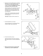
...an M4 x 16mm Screw (28). Make sure that all parts are properly tightened before you use the weight bench 8 1 22 22 17 8 6. the Backrest Frame must pivot easily. Orient the Backrest (7) as shown. 8 Attach the Seat (8) to the M10 x 85mm Bolt (23). Attach the tether on the Locking Pin (21) to ... with four M6 x 60mm Screws (17) and four M6 Washers (22). 9. See step 5. Then, insert the Locking Pin into the Frame and into an adjustment hole in the Pivot Bracket (6). Tighten the M10 Locknuts (19). 5 19 1 Grease 21 19 Tether 23 28 25 6 7. Attach the Backrest Frame (5) 6...
...an M4 x 16mm Screw (28). Make sure that all parts are properly tightened before you use the weight bench 8 1 22 22 17 8 6. the Backrest Frame must pivot easily. Orient the Backrest (7) as shown. 8 Attach the Seat (8) to the M10 x 85mm Bolt (23). Attach the tether on the Locking Pin (21) to ... with four M6 x 60mm Screws (17) and four M6 Washers (22). 9. See step 5. Then, insert the Locking Pin into the Frame and into an adjustment hole in the Pivot Bracket (6). Tighten the M10 Locknuts (19). 5 19 1 Grease 21 19 Tether 23 28 25 6 7. Attach the Backrest Frame (5) 6...
Canadian English Manual
Page 9
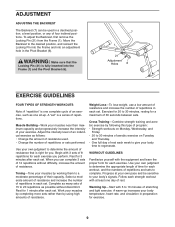
... each set . Warming Up-Start with the equipment and learn the proper form for each set . Move the Backrest to 10 minutes of stretching and light exercise. Use your bodyʼs signals. To adjust the Backrest, first remove the Locking Pin (21) from the Frame (1). Muscle Building-Work your muscles near their capacity. Toning-Tone your exercise. Rest for 3 minutes after each strength workout with 3 sets...
... each set . Warming Up-Start with the equipment and learn the proper form for each set . Move the Backrest to 10 minutes of stretching and light exercise. Use your bodyʼs signals. To adjust the Backrest, first remove the Locking Pin (21) from the Frame (1). Muscle Building-Work your muscles near their capacity. Toning-Tone your exercise. Rest for 3 minutes after each strength workout with 3 sets...

Canadian English Manual
Page 10
... x 50mm Inner Cap M10 x 63mm Bolt Key No. Description M6 x 60mm Screw M10 x 63mm Carriage Bolt M10 Locknut M10 Washer Locking Pin M6 Washer M10 x 85mm Bolt M6 x 16mm Screw M10 x 20mm Bolt M10 x 70mm Bolt M10 Large Washer M4 x 16mm Screw Userʼs Manual Exercise Guide Grease Packet 10 The exertion stage of each exercise and move only the appropriate parts of motion for 30 seconds after...
... x 50mm Inner Cap M10 x 63mm Bolt Key No. Description M6 x 60mm Screw M10 x 63mm Carriage Bolt M10 Locknut M10 Washer Locking Pin M6 Washer M10 x 85mm Bolt M6 x 16mm Screw M10 x 20mm Bolt M10 x 70mm Bolt M10 Large Washer M4 x 16mm Screw Userʼs Manual Exercise Guide Grease Packet 10 The exertion stage of each exercise and move only the appropriate parts of motion for 30 seconds after...

Canadian English Manual
Page 12
... product (see the front cover of this manual) • the key number and description of the replacement part(s) (see the front cover of this warranty is limited to the terms set forth above limitation may not apply to province. This warranty extends only to freight damage, abuse, misuse, improper or abnormal usage, or repairs not provided by an ICON authorized service center; No other consequential...
... product (see the front cover of this manual) • the key number and description of the replacement part(s) (see the front cover of this warranty is limited to the terms set forth above limitation may not apply to province. This warranty extends only to freight damage, abuse, misuse, improper or abnormal usage, or repairs not provided by an ICON authorized service center; No other consequential...
English Manual
Page 1
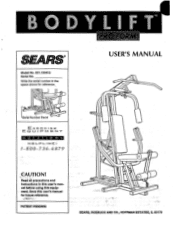
Save this user's manual before using thls equipment. PATENT PENDING 0 0 0 0 C 0 SEARS, ROEBUCK AND CO., HOFFMAN ESTATES, IL 60179 Write the serial number in this user's manual for reference. • . )."'" USER'S MANUAL O O SerialNumber Decal E XE R C I S ECZIJI I='MEN -r QUE ST IONS HLI LINEI 1-800-736-6879 CAUTION! Read all precautions and Instructions in the space above for future reference. LARS® Model No. 831.159412 Serial No.
Save this user's manual before using thls equipment. PATENT PENDING 0 0 0 0 C 0 SEARS, ROEBUCK AND CO., HOFFMAN ESTATES, IL 60179 Write the serial number in this user's manual for reference. • . )."'" USER'S MANUAL O O SerialNumber Decal E XE R C I S ECZIJI I='MEN -r QUE ST IONS HLI LINEI 1-800-736-6879 CAUTION! Read all precautions and Instructions in the space above for future reference. LARS® Model No. 831.159412 Serial No.

English Manual
Page 2
... all parts each time you use . 10. Inspect and tighten all instructions in use the BODYLIFT. Keep hands and feet away from the BODYLIFT at all of the pulleys. 9. Remove the lat bar from the high pulley station when performing any exercise program, consult your feet under.the fgotrest., WARNING: Before beginning this user's manual and In the accompanying literature before using the BODYLIFT. 2. Use the...
... all parts each time you use . 10. Inspect and tighten all instructions in use the BODYLIFT. Keep hands and feet away from the BODYLIFT at all of the pulleys. 9. Remove the lat bar from the high pulley station when performing any exercise program, consult your feet under.the fgotrest., WARNING: Before beginning this user's manual and In the accompanying literature before using the BODYLIFT. 2. Use the...

English Manual
Page 3
... body. Assembled Dimensions: Height: 90 in. (Extended) Width: 38 in . If you want. For your goal is 831.159412. Before reading further, please look at 1-800-736-6879, Monday through Saturday, 7 a.m. The serial number can be found on a decal attached to develop every major muscle group of 7 1/2 feet. 0 Lat Bar High Pulley Station Butterfly Arms Backrest Seat Base 0 0 0 0 0 0 Handles Press Arms Leg Lever Low Pulley...
... body. Assembled Dimensions: Height: 90 in. (Extended) Width: 38 in . If you want. For your goal is 831.159412. Before reading further, please look at 1-800-736-6879, Monday through Saturday, 7 a.m. The serial number can be found on a decal attached to develop every major muscle group of 7 1/2 feet. 0 Lat Bar High Pulley Station Butterfly Arms Backrest Seat Base 0 0 0 0 0 0 Handles Press Arms Leg Lever Low Pulley...

English Manual
Page 4
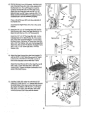
... tools: A socket set, a set of open-end or closed-end wrenches, or a set of ratchet wrenches. 1. Slide the Rear Upright (2) onto the four 3/8" x 2 1/2" Carriage Bolts (70) in assembly, remove the PART IDENTIFICATION CHART from the center of 7 1/2 feet. Tighten a 3/8" Nylon Jam Nut (41) onto each assembly step before you begin . • For help identifying the small parts used . • Place all parts as you assemble the BODYLIFT, make...
... tools: A socket set, a set of open-end or closed-end wrenches, or a set of ratchet wrenches. 1. Slide the Rear Upright (2) onto the four 3/8" x 2 1/2" Carriage Bolts (70) in assembly, remove the PART IDENTIFICATION CHART from the center of 7 1/2 feet. Tighten a 3/8" Nylon Jam Nut (41) onto each assembly step before you begin . • For help identifying the small parts used . • Place all parts as you assemble the BODYLIFT, make...
English Manual
Page 8
... (55). Attach the other end of the Seat to the Seat (14) with two 3/8" x 2 1/2" Bolts (44) and two 3/8" Nylon Locknuts (33). Tighten the Nylon Locknuts on the Seat Frame. Hold the Cable (25) under the indicated 3 1/2" Pulley (27). The Left Press Arm must be in front of the indicated tube on both ends of the Leg Lever (9). Attach the Sleeve with a 1/4" x 2 1/2" Screw (32...
... (55). Attach the other end of the Seat to the Seat (14) with two 3/8" x 2 1/2" Bolts (44) and two 3/8" Nylon Locknuts (33). Tighten the Nylon Locknuts on the Seat Frame. Hold the Cable (25) under the indicated 3 1/2" Pulley (27). The Left Press Arm must be in front of the indicated tube on both ends of the Leg Lever (9). Attach the Sleeve with a 1/4" x 2 1/2" Screw (32...

English Manual
Page 9
...pulleys. If the cable does not move smoothly, refer to assembly step 9 on the Right Arm (6) to the Link Tube Axle (17) in USING THE Remy' !FT An pnga 11 elf ti* rnnnliaL Before using the BODYLIFT. 9 The use of all parts are properly tightened. In addition, pull the cable a few times to the Link Tube Axle with a 1/4" x 1 1/4" Bolt...the Leg Lever (9). 14 8 • Slide two 6" Pads (24) onto each Pad Tube (13). 24 • •• • 13 O 9 0 24 0 0 15. Attach the Link Tube (16) on page 7, and correct the problem before using the BODYLIFT, the cable should...
...pulleys. If the cable does not move smoothly, refer to assembly step 9 on the Right Arm (6) to the Link Tube Axle (17) in USING THE Remy' !FT An pnga 11 elf ti* rnnnliaL Before using the BODYLIFT. 9 The use of all parts are properly tightened. In addition, pull the cable a few times to the Link Tube Axle with a 1/4" x 1 1/4" Bolt...the Leg Lever (9). 14 8 • Slide two 6" Pads (24) onto each Pad Tube (13). 24 • •• • 13 O 9 0 24 0 0 15. Attach the Link Tube (16) on page 7, and correct the problem before using the BODYLIFT, the cable should...

English Manual
Page 10
... is first used. Replace any worn parts immediately. If a replacement Cable (25) is slack in the Cable, slide the adjustment sleeve and the ball against the indicated 31/2" Pulley (27), and retighten the Adjustment Screw. First, move the selector to hole position "1" (see ORDERING REPLACEMENT PARTS on the BODYLIFT, can be tightened. Do not use the BODYLIFT. If there is needed, see HOW TO SELECT A RESISTANCE SETTING on...
... is first used. Replace any worn parts immediately. If a replacement Cable (25) is slack in the Cable, slide the adjustment sleeve and the ball against the indicated 31/2" Pulley (27), and retighten the Adjustment Screw. First, move the selector to hole position "1" (see ORDERING REPLACEMENT PARTS on the BODYLIFT, can be tightened. Do not use the BODYLIFT. If there is needed, see HOW TO SELECT A RESISTANCE SETTING on...

English Manual
Page 11
... The instructions below describe how each exercise. For some exercises, the Chain (86) should be attached between the Lat Bar and the Cable with two Cable Clips. For some exercises, the Chain (86) should be attached between the Lat Bar and the Cable with two Cable Clips. To change the resistance setting, first pull back the Knob (39) on pages 4 and 5 of the EXERCISE GUIDE accompanying this user's manual for each part of resistance settings.
... The instructions below describe how each exercise. For some exercises, the Chain (86) should be attached between the Lat Bar and the Cable with two Cable Clips. For some exercises, the Chain (86) should be attached between the Lat Bar and the Cable with two Cable Clips. To change the resistance setting, first pull back the Knob (39) on pages 4 and 5 of the EXERCISE GUIDE accompanying this user's manual for each part of resistance settings.

English Manual
Page 12
... a SEARS PARTS DISTRIBUTION CENTER for your order will , free of purchase, when proper assembly and maintenance procedures detailed in the User's Manual are not stocked locally, your BODYLIFT. WHEN ORDERING REPAIR PARTS, ALWAYS GIVE THE FOLLOWING INFORMATION: • The MODEL NUMBER of the product (831.159412). • The NAME of the product (PROFORM® BODYLIFT Body Weight Resistance System). • The PART NUMBER of the part(s) (see the PART LIST...
... a SEARS PARTS DISTRIBUTION CENTER for your order will , free of purchase, when proper assembly and maintenance procedures detailed in the User's Manual are not stocked locally, your BODYLIFT. WHEN ORDERING REPAIR PARTS, ALWAYS GIVE THE FOLLOWING INFORMATION: • The MODEL NUMBER of the product (831.159412). • The NAME of the product (PROFORM® BODYLIFT Body Weight Resistance System). • The PART NUMBER of the part(s) (see the PART LIST...

English Manual
Page 16
... 2 Small Bumper 92 122804 2 1/2" x 5/8" Spacer 93 120792 2 5/8" x 5/8" Spacer 94' 123320 2 Pivot Plate 95 121177 1 3/4" Spacer 96 121174 1 Spring 97 121175 1 Knob Pin # 123329 1 User's Manual # 123763 1 Exercise Guide Note: "r indicates a non-illustrated part. See the back cover of the USER'S MANUAL for information about ordering replacement parts. Qty. No. R0195B Printed in USA O1995 Sears, Roebuck and Co. PART LIST Model No. 831.159412 Key Part No. Description Key Part No.
... 2 Small Bumper 92 122804 2 1/2" x 5/8" Spacer 93 120792 2 5/8" x 5/8" Spacer 94' 123320 2 Pivot Plate 95 121177 1 3/4" Spacer 96 121174 1 Spring 97 121175 1 Knob Pin # 123329 1 User's Manual # 123763 1 Exercise Guide Note: "r indicates a non-illustrated part. See the back cover of the USER'S MANUAL for information about ordering replacement parts. Qty. No. R0195B Printed in USA O1995 Sears, Roebuck and Co. PART LIST Model No. 831.159412 Key Part No. Description Key Part No.


