
Uk Manual
Page 9
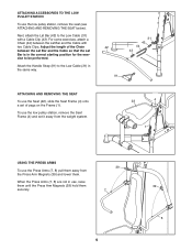
... the Low Cable (31) in the same way. 31 43 42 44 43 91 ATTACHING AND REMOVING THE SEAT To use , raise them until the Press Arm Magnets (39) hold them securely. 39 7 9 39 8 Attach the Handle Strap (91) to the Low Cable (31) with two Cable Clips. Adjust the length... Bar and the Cable so that the Lat Bar is in use the Seat (22), slide the Seat Frame (4) onto a set it away from the Press Arm Magnets (39) and lower them. ATTACHING ACCESSORIES TO THE LOW PULLEY STATION To use the...
... the Low Cable (31) in the same way. 31 43 42 44 43 91 ATTACHING AND REMOVING THE SEAT To use , raise them until the Press Arm Magnets (39) hold them securely. 39 7 9 39 8 Attach the Handle Strap (91) to the Low Cable (31) with two Cable Clips. Adjust the length... Bar and the Cable so that the Lat Bar is in use the Seat (22), slide the Seat Frame (4) onto a set it away from the Press Arm Magnets (39) and lower them. ATTACHING ACCESSORIES TO THE LOW PULLEY STATION To use the...
Uk Manual
Page 12
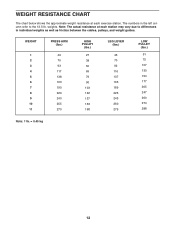
... numbers in the left column refer to differences in individual weights as well as friction between the cables, pulleys, and weight guides. WEIGHT 1 2 3 4 5 6 7 8 9 10 11 PRESS ARM (lbs.) 49 75 93 117 138 163 190 220 240 255 270 HIGH PULLEY (lbs.) 27 38 50 69 79... 90 103 122 137 153 168 LEG LEVER (lbs.) 43 70 92 116 137 163 189 226 243 260 275 LOW PULLEY (lbs.) 51 75 107 ...
... numbers in the left column refer to differences in individual weights as well as friction between the cables, pulleys, and weight guides. WEIGHT 1 2 3 4 5 6 7 8 9 10 11 PRESS ARM (lbs.) 49 75 93 117 138 163 190 220 240 255 270 HIGH PULLEY (lbs.) 27 38 50 69 79... 90 103 122 137 153 168 LEG LEVER (lbs.) 43 70 92 116 137 163 189 226 243 260 275 LOW PULLEY (lbs.) 51 75 107 ...
Uk Manual
Page 14
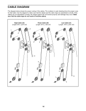
CABLE DIAGRAM The diagram below shows the proper routing of the cables. High Cable (30) Length: 84 in. (214 cm) 4 1 2 Press Cable (29) Length: 64 in. (163 cm) 1 Low Cable (31) Length: 154 in each drawing show the proper route for that the cable traps do not touch or bind the cables. Use the diagram to make sure that the cables and the cable traps are not assembled correctly, the weight system will not function properly and damage may occur. If the cables are assembled correctly. Make sure that cable. The numbers in . (391 cm) 3 2 3 4 5 4 2 5 1 3 14
CABLE DIAGRAM The diagram below shows the proper routing of the cables. High Cable (30) Length: 84 in. (214 cm) 4 1 2 Press Cable (29) Length: 64 in. (163 cm) 1 Low Cable (31) Length: 154 in each drawing show the proper route for that the cable traps do not touch or bind the cables. Use the diagram to make sure that the cables and the cable traps are not assembled correctly, the weight system will not function properly and damage may occur. If the cables are assembled correctly. Make sure that cable. The numbers in . (391 cm) 3 2 3 4 5 4 2 5 1 3 14
Uk Manual
Page 17
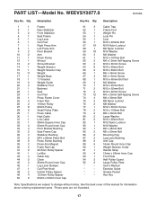
... 2 66 1 67 4 68 1 69 4 70 1 71 2 72 2 73 12 74 4 75 2 76 2 77 1 78 2 79 2 80 2 81 2 82 1 83 1 84 1 85 2 86 2 87 2 88 2 89 6 90 1 91 1 92 4 93 1 94 2 95 2 * - * - * - * - Qty. 1 1 2 1 3 2 4 1 5 1 6 1 7 1 8 1 9 2 10 2 11 1 12 1 13 2 14 1 15 1 16 11 17 1 18 1 19 2 20 ... Cap 50mm Round Inner Cap Pivot Bracket Bushing Seat Frame Cap Stabilizer Bushing M10 x 65mm Patch Bolt Press Frame Bushing Press Arm Magnet Foam Pad Cap 25.5mm Pulley Spacer Lat Bar Cable Clip Chain 25mm Round Inner Cap...
... 2 66 1 67 4 68 1 69 4 70 1 71 2 72 2 73 12 74 4 75 2 76 2 77 1 78 2 79 2 80 2 81 2 82 1 83 1 84 1 85 2 86 2 87 2 88 2 89 6 90 1 91 1 92 4 93 1 94 2 95 2 * - * - * - * - Qty. 1 1 2 1 3 2 4 1 5 1 6 1 7 1 8 1 9 2 10 2 11 1 12 1 13 2 14 1 15 1 16 11 17 1 18 1 19 2 20 ... Cap 50mm Round Inner Cap Pivot Bracket Bushing Seat Frame Cap Stabilizer Bushing M10 x 65mm Patch Bolt Press Frame Bushing Press Arm Magnet Foam Pad Cap 25.5mm Pulley Spacer Lat Bar Cable Clip Chain 25mm Round Inner Cap...


