
Canadian English Manual
Page 2
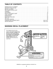
... shown. TABLE OF CONTENTS WARNING DECAL PLACEMENT 2 IMPORTANT PRECAUTIONS 3 BEFORE YOU BEGIN 4 PART IDENTIFICATION CHART 5 ASSEMBLY 6 ADJUSTMENT 18 WEIGHT RESISTANCE CHART 20 CABLE DIAGRAM 21 MAINTENANCE 22 EXERCISE GUIDELINES 23 PART LIST 25 EXPLODED DRAWING 26 ORDERING REPLACEMENT PARTS Back Cover LIMITED WARRANTY Back Cover WARNING DECAL PLACEMENT This... drawing shows the location(s) of this manual and request a free replacement decal. Note: The decal(s) may not be shown at actual size. WEIDER is missing or illegible, see the front cover of the warning decal(s).
... shown. TABLE OF CONTENTS WARNING DECAL PLACEMENT 2 IMPORTANT PRECAUTIONS 3 BEFORE YOU BEGIN 4 PART IDENTIFICATION CHART 5 ASSEMBLY 6 ADJUSTMENT 18 WEIGHT RESISTANCE CHART 20 CABLE DIAGRAM 21 MAINTENANCE 22 EXERCISE GUIDELINES 23 PART LIST 25 EXPLODED DRAWING 26 ORDERING REPLACEMENT PARTS Back Cover LIMITED WARRANTY Back Cover WARNING DECAL PLACEMENT This... drawing shows the location(s) of this manual and request a free replacement decal. Note: The decal(s) may not be shown at actual size. WEIDER is missing or illegible, see the front cover of the warning decal(s).

Canadian English Manual
Page 10
... M10 x 51mm Bolt (66). Attach a Handle (11) to the Pivot Frame (5) in the same way. 10. See the CABLE DIAGRAM on the Shoulder Bolt. 10 58 39 54 Grease 65 the Cable Pivot must pivot easily. the Right Arm must pivot easily. Grease an M8 x 22mm Shoulder Bolt (65). Attach... a Cable Pivot (39) to identify and route the cables. Identify the Arm Cable (54). Do not overtighten the Nylon Locknut; Make sure that the cable end can pivot easily on page 21 to the Left Arm (10) with soapy water...
... M10 x 51mm Bolt (66). Attach a Handle (11) to the Pivot Frame (5) in the same way. 10. See the CABLE DIAGRAM on the Shoulder Bolt. 10 58 39 54 Grease 65 the Cable Pivot must pivot easily. the Right Arm must pivot easily. Grease an M8 x 22mm Shoulder Bolt (65). Attach... a Cable Pivot (39) to identify and route the cables. Identify the Arm Cable (54). Do not overtighten the Nylon Locknut; Make sure that the cable end can pivot easily on page 21 to the Left Arm (10) with soapy water...
Canadian English Manual
Page 17
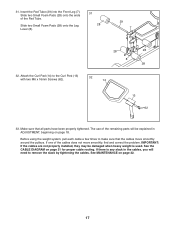
See the CABLE DIAGRAM on page 22. 17 31. Insert the Pad Tube (29) into the Front Leg (7). Attach the Curl Pad (14) to remove the slack by tightening the cables. If there is used. Slide two Small Foam Pads (28) onto the ends of the cables does not move smoothly around the pulleys. The... will need to the Curl Post (13) with two M6 x 16mm Screws (62). 32 14 13 62 33. Before using the weight system, pull each cable a few times to make sure that all parts have been properly tightened. Slide two Small Foam Pads (28) onto the Leg Lever (8). 31 28 29...
See the CABLE DIAGRAM on page 22. 17 31. Insert the Pad Tube (29) into the Front Leg (7). Attach the Curl Pad (14) to remove the slack by tightening the cables. If there is used. Slide two Small Foam Pads (28) onto the ends of the cables does not move smoothly around the pulleys. The... will need to the Curl Post (13) with two M6 x 16mm Screws (62). 32 14 13 62 33. Before using the weight system, pull each cable a few times to make sure that all parts have been properly tightened. Slide two Small Foam Pads (28) onto the Leg Lever (8). 31 28 29...

Canadian English Manual
Page 21
... ft. 8 in each drawing show the proper route of the cables. Use the diagram to make sure that the cables, cable traps, pulleys, and guards are not assembled correctly, the weight system will not function properly and damage may occur. CABLE DIAGRAM The diagram below shows the proper routing of that cable. The numbers in . (325 cm) 21
... ft. 8 in each drawing show the proper route of the cables. Use the diagram to make sure that the cables, cable traps, pulleys, and guards are not assembled correctly, the weight system will not function properly and damage may occur. CABLE DIAGRAM The diagram below shows the proper routing of that cable. The numbers in . (325 cm) 21


