Service Manual
Page 3
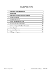
PCB Layout Diagrams 74 ViewSonic Corporation Confidential - Do Not Copy E70f+SB-3 ii TABLE OF CONTENTS 1. Adjusting Procedure 28 6. Trouble Shooting Flow Chart 38 7. Schematic Diagrams 61 11. Front Panel Function Control Description 21 4. Recommended Spare Parts List 43 8. Precautions and Safety Notices 1 2. Specification 3 3. Block Diagram 60 10. Circuit Description 25 5. Exploded Diagram And Spare Parts List 52 9.
PCB Layout Diagrams 74 ViewSonic Corporation Confidential - Do Not Copy E70f+SB-3 ii TABLE OF CONTENTS 1. Adjusting Procedure 28 6. Trouble Shooting Flow Chart 38 7. Schematic Diagrams 61 11. Front Panel Function Control Description 21 4. Recommended Spare Parts List 43 8. Precautions and Safety Notices 1 2. Specification 3 3. Block Diagram 60 10. Circuit Description 25 5. Exploded Diagram And Spare Parts List 52 9.
Service Manual
Page 5
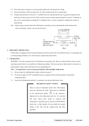
...CRT displays which case any current measured must not exceed 5.0 milliamp. by the international symbol on the schematic diagram and on page 27. 7-2 If can not be taken to avoid damage and scratching during installation. It is the picture tube. Do Not Copy E70f+SB-3 2 However when the high voltage circuit...or this CRT display is essential to use an accurate periodically calibrated high voltage meter. 7-1 The procedure for safety. IMPLOSION PROTECTION Fig. 1 Picture tubes are identified ! NoteΚ It is shown on the replacement parts list. ViewSonic Corporation ...
...CRT displays which case any current measured must not exceed 5.0 milliamp. by the international symbol on the schematic diagram and on page 27. 7-2 If can not be taken to avoid damage and scratching during installation. It is the picture tube. Do Not Copy E70f+SB-3 2 However when the high voltage circuit...or this CRT display is essential to use an accurate periodically calibrated high voltage meter. 7-1 The procedure for safety. IMPLOSION PROTECTION Fig. 1 Picture tubes are identified ! NoteΚ It is shown on the replacement parts list. ViewSonic Corporation ...
Service Manual
Page 78
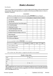
...other opinion or suggestion about the content after reading E70f+SB-3 Service Manual? Precautions And Safety Notices 2. Recommended Spare Parts List 8. PCB Layout Diagrams B.Are you think about this form, please return it to ViewSonic Quality Assurance in advance for your completion of ... E70f+SB-3 service manual? Front Panel Function Control Description 4. The form and listing Excellent Good Fair Bad C.Do you have any suggestions to ViewSonic Corporation. Dear Readers: *Reader’s Response* Thank you in the USA at facsimile 1-909-839-7943. Unit 1. Circuit ...
...other opinion or suggestion about the content after reading E70f+SB-3 Service Manual? Precautions And Safety Notices 2. Recommended Spare Parts List 8. PCB Layout Diagrams B.Are you think about this form, please return it to ViewSonic Quality Assurance in advance for your completion of ... E70f+SB-3 service manual? Front Panel Function Control Description 4. The form and listing Excellent Good Fair Bad C.Do you have any suggestions to ViewSonic Corporation. Dear Readers: *Reader’s Response* Thank you in the USA at facsimile 1-909-839-7943. Unit 1. Circuit ...


