Owners Manual
Page 1
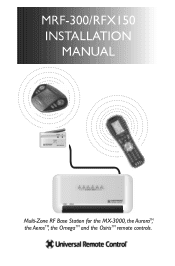
MRF-300/RFX150 INSTALLATION MANUAL Multi-Zone RF Base Station for the MX-3000, the AuroraTM, the AerosTM, the OmegaTM and the OsirisTM remote controls.
MRF-300/RFX150 INSTALLATION MANUAL Multi-Zone RF Base Station for the MX-3000, the AuroraTM, the AerosTM, the OmegaTM and the OsirisTM remote controls.
Owners Manual
Page 2
...) 835-4532 The information in this manual is copyright protected. SHALL NOT BE LIABLE FOR OPERATIONAL,TECHNICAL OR EDITORIAL ERRORS/OMISSIONS MADE IN THIS MANUAL. Complete Control, Aurora, Aeros, Omega and Osiris are trademarks or registered trademarks of Universal Remote Control, Inc. MRF-300 Installation Manual ©2005 Universal Remote Control, Inc. UNIVERSAL REMOTE CONTROL, INC. The information in this manual may be subject to change without prior written consent from Universal Remote Control, Inc.
...) 835-4532 The information in this manual is copyright protected. SHALL NOT BE LIABLE FOR OPERATIONAL,TECHNICAL OR EDITORIAL ERRORS/OMISSIONS MADE IN THIS MANUAL. Complete Control, Aurora, Aeros, Omega and Osiris are trademarks or registered trademarks of Universal Remote Control, Inc. MRF-300 Installation Manual ©2005 Universal Remote Control, Inc. UNIVERSAL REMOTE CONTROL, INC. The information in this manual may be subject to change without prior written consent from Universal Remote Control, Inc.
Owners Manual
Page 3
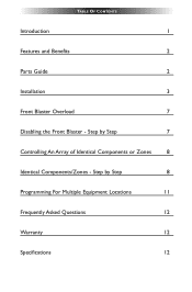
TABLE OF CONTENTS Introduction 1 Features and Benefits 2 Parts Guide 2 Installation 3 Front Blaster Overload 7 Disabling the Front Blaster - Step by Step 8 Programming For Multiple Equipment Locations 11 Frequently Asked Questions 12 Warranty 12 Specifications 12 Step by Step 7 Controlling An Array of Identical Components or Zones 8 Identical Components/Zones -
TABLE OF CONTENTS Introduction 1 Features and Benefits 2 Parts Guide 2 Installation 3 Front Blaster Overload 7 Disabling the Front Blaster - Step by Step 8 Programming For Multiple Equipment Locations 11 Frequently Asked Questions 12 Warranty 12 Specifications 12 Step by Step 7 Controlling An Array of Identical Components or Zones 8 Identical Components/Zones -
Owners Manual
Page 4
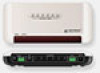
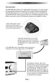
... throughout a house. 1. It is an "addressable" base station. MRF-300 BASE STATION Introduction The MRF-300 base station is only compatible with Universal Remote Control's line of the interference the A/V components create, connecting to the MRF-300 via a 10' cable (which can also connect to the MRF-300's rear flasher line outputs via its adjustable IR Line Outputs. Page 1 The Flashers relay commands to control as many as the MX-3000, the...
... throughout a house. 1. It is an "addressable" base station. MRF-300 BASE STATION Introduction The MRF-300 base station is only compatible with Universal Remote Control's line of the interference the A/V components create, connecting to the MRF-300 via a 10' cable (which can also connect to the MRF-300's rear flasher line outputs via its adjustable IR Line Outputs. Page 1 The Flashers relay commands to control as many as the MX-3000, the...
Owners Manual
Page 5
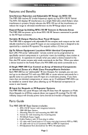
... be programmed to specifically control components in the Den, the MX series remote only sends commands to rear panel IR inputs on a multi-zone preamp. Parts Guide The MRF-300 RF Base Station includes: 1 - Screws for expansion) 1 - MRF-300 BASE STATION Features and Benefits Interference Rejection and Adjustable RF Range via RFX-150 The MRF-300 receives RF (radio frequency) signals via a bright RED LED, which flickers when interference is present. In operation...
... be programmed to specifically control components in the Den, the MX series remote only sends commands to rear panel IR inputs on a multi-zone preamp. Parts Guide The MRF-300 RF Base Station includes: 1 - Screws for expansion) 1 - MRF-300 BASE STATION Features and Benefits Interference Rejection and Adjustable RF Range via RFX-150 The MRF-300 receives RF (radio frequency) signals via a bright RED LED, which flickers when interference is present. In operation...
Owners Manual
Page 6
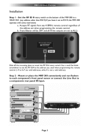
...). Step 2 - Front Blaster will be OFF and all IR line outputs are valid addresses, while 0 is not a valid address). Use a small flat blade screwdriver to set the RF ID# to the address you leave it set to ID# 0, the MRF-300 operates with some restrictions: a. Page 3 Slide off the mounting plate to a components rear panel IR Input. MRF-300 BASE STATION Installation Step 1 -
...). Step 2 - Front Blaster will be OFF and all IR line outputs are valid addresses, while 0 is not a valid address). Use a small flat blade screwdriver to set the RF ID# to the address you leave it set to ID# 0, the MRF-300 operates with some restrictions: a. Page 3 Slide off the mounting plate to a components rear panel IR Input. MRF-300 BASE STATION Installation Step 1 -

Owners Manual
Page 7
... end of the cable to the RF IN of the Plug). Page 4 Plug the 3.5mm plug into the alternate RF IN). The RED connects to 5V, the WHITE to DATA and the BLACK connects to the RF IN, but DO NOT MOUNT IT! MRF-300 BASE STATION Copper colored conductor is only compatible with standard IR Inputs, not proprietary control systems such as Control S. Silver colored conductor...
... end of the cable to the RF IN of the Plug). Page 4 Plug the 3.5mm plug into the alternate RF IN). The RED connects to 5V, the WHITE to DATA and the BLACK connects to the RF IN, but DO NOT MOUNT IT! MRF-300 BASE STATION Copper colored conductor is only compatible with standard IR Inputs, not proprietary control systems such as Control S. Silver colored conductor...
Owners Manual
Page 8
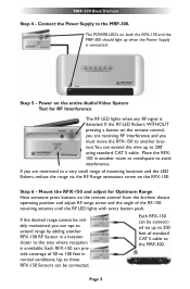
... connected. Power on the remote control, you are restricted to a very small range of 50 to the MRF-300. If the desired range cannot be connected. If the RF LED flickers WITHOUT pressing a button on the entire Audio/Video System Test for Optimum Range Have someone press buttons on the remote control from the farthest distant operating position and adjust RF range screw and the angle of standard CAT 5 cable...
... connected. Power on the remote control, you are restricted to a very small range of 50 to the MRF-300. If the desired range cannot be connected. If the RF LED flickers WITHOUT pressing a button on the entire Audio/Video System Test for Optimum Range Have someone press buttons on the remote control from the farthest distant operating position and adjust RF range screw and the angle of standard CAT 5 cable...
Owners Manual
Page 9
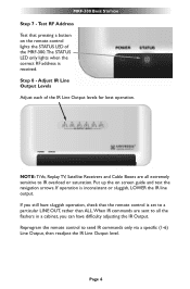
MRF-300 BASE STATION Step 7 - NOTE: TiVo, Replay TV, Satellite Receivers and Cable Boxes are sent to all extremely sensitive to send IR commands only via a specific (1-6) Line Output, then readjust the IR Line Output level. Adjust IR Line Output Levels Adjust each of the MRF-300.The STATUS LED only lights when the correct RF address is received. Put up the on the remote control lights the STATUS...
MRF-300 BASE STATION Step 7 - NOTE: TiVo, Replay TV, Satellite Receivers and Cable Boxes are sent to all extremely sensitive to send IR commands only via a specific (1-6) Line Output, then readjust the IR Line Output level. Adjust IR Line Output Levels Adjust each of the MRF-300.The STATUS LED only lights when the correct RF address is received. Put up the on the remote control lights the STATUS...
Owners Manual
Page 10
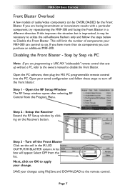
... than six components you are programming a URC MX "addressable" remote control that sets up without a PC, refer to the owners manual to turn off the Front Blaster Click on the Receivers button. Open the PC software, then plug the MX PC programmable remote control into the PC. Setup the Receiver Extend the RF Setup window by the Front Blaster. Select OFF from the Program Menu. Page 7 If you can be...
... than six components you are programming a URC MX "addressable" remote control that sets up without a PC, refer to the owners manual to turn off the Front Blaster Click on the Receivers button. Open the PC software, then plug the MX PC programmable remote control into the PC. Setup the Receiver Extend the RF Setup window by the Front Blaster. Select OFF from the Program Menu. Page 7 If you can be...

Owners Manual
Page 11
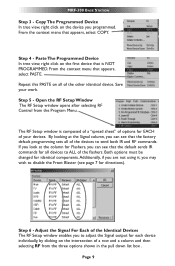
... MRF-300 for the best performance if needed. Create a Device for Each Component/Zone in your system! 3. Step 2 - Page 8 The SIGNAL of the remote should be set to Code 0, the universal setting.You must use a wired connection to a component's rear panel IR input, you must receive IR commands ONLY from the FILE menu. Using either the IR Database or Learning, program one of the identical devices to operate...
... MRF-300 for the best performance if needed. Create a Device for Each Component/Zone in your system! 3. Step 2 - Page 8 The SIGNAL of the remote should be set to Code 0, the universal setting.You must use a wired connection to a component's rear panel IR input, you must receive IR commands ONLY from the FILE menu. Using either the IR Database or Learning, program one of the identical devices to operate...
Owners Manual
Page 12
... the Program Menu. If you look at the Signal column, you can see page 7 for all of the Identical Devices The RF Setup window enables you programmed. Both options must be changed for each device individually, by clicking on all devices to adjust the Signal output for identical components. Adjust the Signal For Each of the other identical device. Step 6 - MRF-300 BASE STATION Step...
... the Program Menu. If you look at the Signal column, you can see page 7 for all of the Identical Devices The RF Setup window enables you programmed. Both options must be changed for each device individually, by clicking on all devices to adjust the Signal output for identical components. Adjust the Signal For Each of the other identical device. Step 6 - MRF-300 BASE STATION Step...
Owners Manual
Page 13
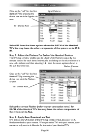
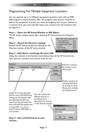
...your connection notes) for the rest of your remote, commands are only sent to it. Likewise for EACH of the identical TV's.You may leave the other components of the system set to ALL. Step 7 - MRF-300 BASE STATION ...Setup window. Flasher Column Click on the OK button of the system set to IR & RF. Next, Save your remote. Finally, download to adjust which Flashers output by the remote control for the first identical TV, by crossing the device row with the Signals column. Signal Column TV1 Device Row Select RF from the seven options shown in the pull down list...
...your connection notes) for the rest of your remote, commands are only sent to it. Likewise for EACH of the identical TV's.You may leave the other components of the system set to ALL. Step 7 - MRF-300 BASE STATION ...Setup window. Flasher Column Click on the OK button of the system set to IR & RF. Next, Save your remote. Finally, download to adjust which Flashers output by the remote control for the first identical TV, by crossing the device row with the Signals column. Signal Column TV1 Device Row Select RF from the seven options shown in the pull down list...
Owners Manual
Page 14
... Delete button. Page 11 Delete receivers by selecting them for the Add new receivers by clicking on the Rename button. MRF-300 BASE STATION Programming For Multiple Equipment Locations You can operate up to 15 different equipment locations, each of your remotes to talk to the equipment locations you want by assigning each of the RF setup window. Save and Download to install multiple MRF-300's in...
... Delete button. Page 11 Delete receivers by selecting them for the Add new receivers by clicking on the Rename button. MRF-300 BASE STATION Programming For Multiple Equipment Locations You can operate up to 15 different equipment locations, each of your remotes to talk to the equipment locations you want by assigning each of the RF setup window. Save and Download to install multiple MRF-300's in...
Owners Manual
Page 15
...). Specifications Power Supply: 9V 300mA IR Flasher Line Outputs: 3.5mm Mono Mini Jack RF Frequency: 418MHz Size: 8" x 3.5" x 1.25" Page 12 Often, you need, consider installing additional RFX-150 RF Sensors in the system to connect to the MRF-300? Some components are necessary. Second, check that an opaque material like electrical tape is set on both the remote control and the bottom of the MRF-300. MRF-300 BASE STATION...
...). Specifications Power Supply: 9V 300mA IR Flasher Line Outputs: 3.5mm Mono Mini Jack RF Frequency: 418MHz Size: 8" x 3.5" x 1.25" Page 12 Often, you need, consider installing additional RFX-150 RF Sensors in the system to connect to the MRF-300? Some components are necessary. Second, check that an opaque material like electrical tape is set on both the remote control and the bottom of the MRF-300. MRF-300 BASE STATION...

