Owners Manual
Page 2
... Complete Control is copyright protected. KP-4000 Installation Manual ©2010 Universal Remote Control, Inc. All other brand or product names are trademarks or registered trademarks of this manual may be copied or reproduced in this manual may be subject to change without prior written consent from Universal Remote Control, Inc. SHALL NOT BE LIABLE FOR OPERATIONAL, TECHNICAL OR EDITORIAL ERRORS/OMISSIONS MADE IN THIS MANUAL.
... Complete Control is copyright protected. KP-4000 Installation Manual ©2010 Universal Remote Control, Inc. All other brand or product names are trademarks or registered trademarks of this manual may be copied or reproduced in this manual may be subject to change without prior written consent from Universal Remote Control, Inc. SHALL NOT BE LIABLE FOR OPERATIONAL, TECHNICAL OR EDITORIAL ERRORS/OMISSIONS MADE IN THIS MANUAL.
Owners Manual
Page 3
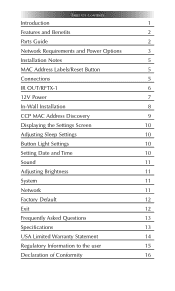
TABLE OF CONTENTS Introduction 1 Features and Benefits 2 Parts Guide 2 Network Requirements and Power Options 3 Installation Notes 5 MAC Address Labels/Reset Button 5 Connections 5 IR OUT/RFTX-1 6 12V Power 7 In-Wall Installation 8 CCP MAC Address Discovery 9 Displaying the Settings Screen 10 Adjusting Sleep Settings 10 Button Light Settings 10 Setting Date and Time 10 Sound 11 Adjusting Brightness 11 System 11 Network 11 Factory Default 12 Exit 12 Frequently Asked Questions 13 Specifications 13 USA Limited Warranty Statement 14 Regulatory ...
TABLE OF CONTENTS Introduction 1 Features and Benefits 2 Parts Guide 2 Network Requirements and Power Options 3 Installation Notes 5 MAC Address Labels/Reset Button 5 Connections 5 IR OUT/RFTX-1 6 12V Power 7 In-Wall Installation 8 CCP MAC Address Discovery 9 Displaying the Settings Screen 10 Adjusting Sleep Settings 10 Button Light Settings 10 Setting Date and Time 10 Sound 11 Adjusting Brightness 11 System 11 Network 11 Factory Default 12 Exit 12 Frequently Asked Questions 13 Specifications 13 USA Limited Warranty Statement 14 Regulatory ...
Owners Manual
Page 4
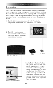
... Station. 2. The flashers plug in to components with rear panel IR Inputs via their 10 foot cables. The KP-4000 communicates over IP with the ability to use an unlimited amount of KP-4000's and allows the control of your client's components. The MRX-1can also connect to the MRX-1 rear flasher line outputs via its adjustable IR Line Outputs. The MRX-1 receives...
... Station. 2. The flashers plug in to components with rear panel IR Inputs via their 10 foot cables. The KP-4000 communicates over IP with the ability to use an unlimited amount of KP-4000's and allows the control of your client's components. The MRX-1can also connect to the MRX-1 rear flasher line outputs via its adjustable IR Line Outputs. The MRX-1 receives...
Owners Manual
Page 5
.... They simply manually adjust each dimmer to the KP-4000 screen and of course, are all available updated to the new setting, then press and hold a scene button on the Now Playing screen of a chair.The KP-4000's optional RFTX-1 transmitter directly controls URC RF Dimmers and Switches. User Configurable Internet RSS for News, Sports, Stocks and Weather The well known URC modules for multi-zone receivers with either...
.... They simply manually adjust each dimmer to the KP-4000 screen and of course, are all available updated to the new setting, then press and hold a scene button on the Now Playing screen of a chair.The KP-4000's optional RFTX-1 transmitter directly controls URC RF Dimmers and Switches. User Configurable Internet RSS for News, Sports, Stocks and Weather The well known URC modules for multi-zone receivers with either...
Owners Manual
Page 6
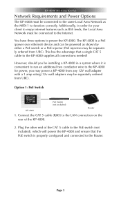
... 5 cable to the PoE switch (not included), which will power the KP-4000 and ensure that a single CAT 5 cable to the KP-4000 supplies all connections needed! The KP-4000 is properly configured and connected to the Router. Plug the other end of the KP-4000. 2. You have three options to power the KP-4000. KP-4000 NETWORK KEYPAD Network Requirements and Power Options The KP-4000 must be connected to...
... 5 cable to the PoE switch (not included), which will power the KP-4000 and ensure that a single CAT 5 cable to the KP-4000 supplies all connections needed! The KP-4000 is properly configured and connected to the Router. Plug the other end of the KP-4000. 2. You have three options to power the KP-4000. KP-4000 NETWORK KEYPAD Network Requirements and Power Options The KP-4000 must be connected to...
Owners Manual
Page 8
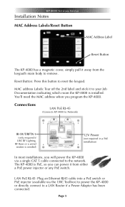
... a single CAT 5 cable connected to the network. KP-4000 NETWORK KEYPAD Installation Notes MAC Address Labels/Reset Button MAC Address Label Reset Button The KP-4000 has a magnetic cover, simply pull it to your Job Documentation indicating which room the KP-4000 is installed. Connections LAN PoE RJ-45 (Connects KP-4000 to Network) IR OUT/RFTX-1 (only required if URC RF Lighting, RF Base or a wired emitter is needed) 12V Power (not required...
... a single CAT 5 cable connected to the network. KP-4000 NETWORK KEYPAD Installation Notes MAC Address Labels/Reset Button MAC Address Label Reset Button The KP-4000 has a magnetic cover, simply pull it to your Job Documentation indicating which room the KP-4000 is installed. Connections LAN PoE RJ-45 (Connects KP-4000 to Network) IR OUT/RFTX-1 (only required if URC RF Lighting, RF Base or a wired emitter is needed) 12V Power (not required...
Owners Manual
Page 9
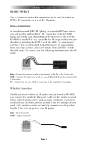
... of the 3.5mm plug 5V - URC emitters can be used for either an RFTX-1 RF transmitter or for a URC IR emitter. KP-4000 NETWORK KEYPAD IR OUT/RFTX-1 This 3 Conductor removable connector can be successfully powered over long cable lengths if the wire gauge is connected to the KP-4000. RFTX-1 Connections In installations with a cable that has a silver and a copper conductor. Range can wildly vary, depending...
... of the 3.5mm plug 5V - URC emitters can be used for either an RFTX-1 RF transmitter or for a URC IR emitter. KP-4000 NETWORK KEYPAD IR OUT/RFTX-1 This 3 Conductor removable connector can be successfully powered over long cable lengths if the wire gauge is connected to the KP-4000. RFTX-1 Connections In installations with a cable that has a silver and a copper conductor. Range can wildly vary, depending...
Owners Manual
Page 10
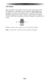
Page 7 GND - You must run an additional two conductor cable to the KP-4000 to the - Connect a spliced power adapter 12Volt, 1AMP with a wall adapter in an installation where PoE is not available. Connect to utilize this feature. Connect to the + conductor of a 12V, 1 Amp DC wall adapter. conductor of a 12V, 1 Amp DC wall adapter. 12V Power KP-4000 NETWORK KEYPAD This 2 conductor removable connector can be used to power the KP-4000 with the polarity (Positive & Negative) connected correctly. + - 12V 1A -
Page 7 GND - You must run an additional two conductor cable to the KP-4000 to the - Connect a spliced power adapter 12Volt, 1AMP with a wall adapter in an installation where PoE is not available. Connect to utilize this feature. Connect to the + conductor of a 12V, 1 Amp DC wall adapter. conductor of a 12V, 1 Amp DC wall adapter. 12V Power KP-4000 NETWORK KEYPAD This 2 conductor removable connector can be used to power the KP-4000 with the polarity (Positive & Negative) connected correctly. + - 12V 1A -
Owners Manual
Page 11
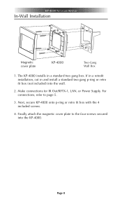
Make connections for IR Out/RFTX-1, LAN, or Power Supply. For connections, refer to the four screws secured into the wall. 2. Page 8 The KP-4000 installs in and install a standard two gang p-ring or retro fit box (not included) into the KP-4000. If in a retrofit installation, cut in a standard two gang box. Next, secure KP-4000 onto p-ring or retro fit box with the 4 included screws. 4. Finally attach the magnetic cover plate to page 5. 3. KP-4000 NETWORK KEYPAD In-Wall Installation Magnetic cover plate KP-4000 Two-Gang Wall Box 1.
Make connections for IR Out/RFTX-1, LAN, or Power Supply. For connections, refer to the four screws secured into the wall. 2. Page 8 The KP-4000 installs in and install a standard two gang p-ring or retro fit box (not included) into the KP-4000. If in a retrofit installation, cut in a standard two gang box. Next, secure KP-4000 onto p-ring or retro fit box with the 4 included screws. 4. Finally attach the magnetic cover plate to page 5. 3. KP-4000 NETWORK KEYPAD In-Wall Installation Magnetic cover plate KP-4000 Two-Gang Wall Box 1.
Owners Manual
Page 12
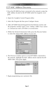
.... 4. Begin programming your unit. 6. Note: Adding a MRX-1 base station to the network. Then press Apply. 7. Add a KP-4000 Network Keypad from the Remotes section and the properties window opens. The Discover window opens to reveal KP-4000's connected to communicate with a KP-4000 is recommended. 5. Open the Complete Control Program editor. 3. Page 9 KP-4000 NETWORK KEYPAD CCP MAC Address Discovery 1.Once the KP-4000 has been connected to select...
.... 4. Begin programming your unit. 6. Note: Adding a MRX-1 base station to the network. Then press Apply. 7. Add a KP-4000 Network Keypad from the Remotes section and the properties window opens. The Discover window opens to reveal KP-4000's connected to communicate with a KP-4000 is recommended. 5. Open the Complete Control Program editor. 3. Page 9 KP-4000 NETWORK KEYPAD CCP MAC Address Discovery 1.Once the KP-4000 has been connected to select...
Owners Manual
Page 13
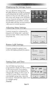
.... Sound Page 10 If you do not press any button on the SETTINGS screen within 1 minute, the KP-4000 will change to turn off the LED lighting behind the buttons. Adjusting Sleep Settings Conserve energy by opting to the SETTINGS screen. Setting Date and Time Your KP-4000 may have been programmed to normal operation. If you do , the screen will time out and automatically return to display the date or time...
.... Sound Page 10 If you do not press any button on the SETTINGS screen within 1 minute, the KP-4000 will change to turn off the LED lighting behind the buttons. Adjusting Sleep Settings Conserve energy by opting to the SETTINGS screen. Setting Date and Time Your KP-4000 may have been programmed to normal operation. If you do , the screen will time out and automatically return to display the date or time...
Owners Manual
Page 14
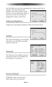
... been programmed to the desired level. This is connect to keep it silent. Factory Default WARNING! System The System Information screen displays data about your KP-4000's operating system, memory etc. Only use this button when instructed to any level you like by Technical Page 11 KP-4000 NETWORK KEYPAD Your KP-4000 may prefer to . Adjusting Brightness Simply touch and drag the brightness slider to make sounds...
... been programmed to the desired level. This is connect to keep it silent. Factory Default WARNING! System The System Information screen displays data about your KP-4000's operating system, memory etc. Only use this button when instructed to any level you like by Technical Page 11 KP-4000 NETWORK KEYPAD Your KP-4000 may prefer to . Adjusting Brightness Simply touch and drag the brightness slider to make sounds...
Owners Manual
Page 15
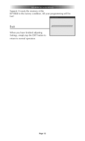
All your programming will be lost! It resets the memory of the KP-4000 to normal operation. Page 12 Exit When you have finished adjusting Settings, simply tap the EXIT button to return to the factory condition. KP-4000 NETWORK KEYPAD Support.
All your programming will be lost! It resets the memory of the KP-4000 to normal operation. Page 12 Exit When you have finished adjusting Settings, simply tap the EXIT button to return to the factory condition. KP-4000 NETWORK KEYPAD Support.
Owners Manual
Page 16
..., TO THE TIME PERIODS COVERED BY THE EXPRESS WRITTEN WARRANTIES PROVIDED HEREIN. URC warrants that URC equipment purchased directly from URC or from an authorized URC dealer or distributor shall be free from defects in any material respect to comply. KP-4000 NETWORK KEYPAD USA Limited Warranty Statement 1. LIMITED WARRANTY AND DISCLAIMERS Universal Remote Control, Inc. ("URC") warrants that the software will substantially conform...
..., TO THE TIME PERIODS COVERED BY THE EXPRESS WRITTEN WARRANTIES PROVIDED HEREIN. URC warrants that URC equipment purchased directly from URC or from an authorized URC dealer or distributor shall be free from defects in any material respect to comply. KP-4000 NETWORK KEYPAD USA Limited Warranty Statement 1. LIMITED WARRANTY AND DISCLAIMERS Universal Remote Control, Inc. ("URC") warrants that the software will substantially conform...
Owners Manual
Page 17
... sale, installation contract or other reason, including but not limited to product issues due to end user in whole or in its sole option, repair the URC equipment using new or comparable rebuilt parts, or exchange the URC equipment for new or rebuilt equipment. Buying URC's PC programmable remotes or any macro programming, artwork, software or other materials that such data, software, or other important information, please visit URC...
... sale, installation contract or other reason, including but not limited to product issues due to end user in whole or in its sole option, repair the URC equipment using new or comparable rebuilt parts, or exchange the URC equipment for new or rebuilt equipment. Buying URC's PC programmable remotes or any macro programming, artwork, software or other materials that such data, software, or other important information, please visit URC...
Owners Manual
Page 18
... the Network then open CCP and click on the RFTX-1 is not eligible for the KP-4000. IN NO EVENT SHALL URC BE LIABLE FOR THE ACTS OR OMISSIONS OF END USER OR ANY THIRD PARTY. URC Lighting Models MRFA is 418MHz and MRFB is connected to the correct frequency for the URC Dimmer or Switch. THIS LIMITED WARRANTY GIVES END USER SPECIFIC...
... the Network then open CCP and click on the RFTX-1 is not eligible for the KP-4000. IN NO EVENT SHALL URC BE LIABLE FOR THE ACTS OR OMISSIONS OF END USER OR ANY THIRD PARTY. URC Lighting Models MRFA is 418MHz and MRFB is connected to the correct frequency for the URC Dimmer or Switch. THIS LIMITED WARRANTY GIVES END USER SPECIFIC...
Owners Manual
Page 19
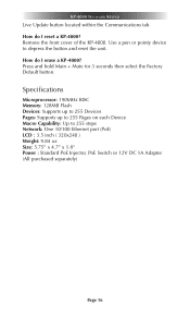
... the Factory Default button. Specifications Microprocessor: 190MHz RISC Memory: 128MB Flash Devices: Supports up to 255 Devices Pages: Supports up to 255 Pages on each Device Macro Capability: Up to depress the button and reset the unit. Use a pen or pointy device to 255 steps Network: One 10/100 Ethernet port (PoE) LCD : 3.5 inch ( 320x240 ) Weight: 9.84 oz Size: 5.75" x 4.7" x 1.8" Power : Standard PoE Injector, PoE Switch...
... the Factory Default button. Specifications Microprocessor: 190MHz RISC Memory: 128MB Flash Devices: Supports up to 255 Devices Pages: Supports up to 255 Pages on each Device Macro Capability: Up to depress the button and reset the unit. Use a pen or pointy device to 255 steps Network: One 10/100 Ethernet port (PoE) LCD : 3.5 inch ( 320x240 ) Weight: 9.84 oz Size: 5.75" x 4.7" x 1.8" Power : Standard PoE Injector, PoE Switch...
Owners Manual
Page 20
... : The manufacturer is connected. Consult the dealer or an experienced radio/TV technician for a Class B digital device, pursuant to radio communications. Such modifications could void the user's authority to provide reasonable protection against harmful interference in a particular installation. The antenna(s) used in conjunction with the instructions, may cause undesired operation. These limits are designed to operate the equipment. However, there...
... : The manufacturer is connected. Consult the dealer or an experienced radio/TV technician for a Class B digital device, pursuant to radio communications. Such modifications could void the user's authority to provide reasonable protection against harmful interference in a particular installation. The antenna(s) used in conjunction with the instructions, may cause undesired operation. These limits are designed to operate the equipment. However, there...

Owners Manual
Page 21
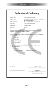
Certification Type No.(Model No.) Batch/Serial No. KP-4000 NETWORK KEYPAD Regulatory Information to the user CE conformity Notice Products with the Essential requirements and other relevant provisions of Conformity "Hereby, Universal Remote Control Inc. declares that this KP-4000 is in compliance with "CE" marking comply EMC Directive 2004/108/EC issued by the commission of the European Community...
Certification Type No.(Model No.) Batch/Serial No. KP-4000 NETWORK KEYPAD Regulatory Information to the user CE conformity Notice Products with the Essential requirements and other relevant provisions of Conformity "Hereby, Universal Remote Control Inc. declares that this KP-4000 is in compliance with "CE" marking comply EMC Directive 2004/108/EC issued by the commission of the European Community...
Owners Manual
Page 22
... Company Name Company Address Contact Info rmation Brand Name Product Name Model Name : Universal Remote Control Inc. : 500Mamaroneck Avenue, Harrison, NY 10528, U.S.A www.universalremote.com : Phone: (914)835-4484 Fax: (914)835-4532 : UNIVERSAL remote control : Network Key pad : KP-4000 This product herewith complies with the requirements of EMC Directive (2004/108/EC) issued bythe Commission of the European Community Compliance...
... Company Name Company Address Contact Info rmation Brand Name Product Name Model Name : Universal Remote Control Inc. : 500Mamaroneck Avenue, Harrison, NY 10528, U.S.A www.universalremote.com : Phone: (914)835-4484 Fax: (914)835-4532 : UNIVERSAL remote control : Network Key pad : KP-4000 This product herewith complies with the requirements of EMC Directive (2004/108/EC) issued bythe Commission of the European Community Compliance...


