
Operation Manual
Page 2
...are observed from the operating position. Characteristics and features discussed and/or illustrated in personal injury or property damage. The engine manufacturer is relative to the most recent product information available at the time of product specifications for more information. Model ...Information Before setting up , operate and maintain your machine, for various models. Please read this manual is responsible for purchasing a Troy-Bilt Snow Thrower. We want to familiarize yourself with a local authorized service dealer. Failure to do NOT return the machine to ...
...are observed from the operating position. Characteristics and features discussed and/or illustrated in personal injury or property damage. The engine manufacturer is relative to the most recent product information available at the time of product specifications for more information. Model ...Information Before setting up , operate and maintain your machine, for various models. Please read this manual is responsible for purchasing a Troy-Bilt Snow Thrower. We want to familiarize yourself with a local authorized service dealer. Failure to do NOT return the machine to ...
Operation Manual
Page 3
... ricochet can cause serious injury to operate this machine. California Proposition 65 WARNING! Be familiar with all machines with electric start engines. 4. Always wear safety glasses or eye shields during operation and while performing an adjustment or repair to protect your snow-throwing... the instructions and safe operation practices in operation. Thrown objects which could be operated according to comply with any adjustments while engine is to observe the following safety instructions could endanger the personal safety and/or property of amputating fingers, hands, toes and...
... ricochet can cause serious injury to operate this machine. California Proposition 65 WARNING! Be familiar with all machines with electric start engines. 4. Always wear safety glasses or eye shields during operation and while performing an adjustment or repair to protect your snow-throwing... the instructions and safe operation practices in operation. Thrown objects which could be operated according to comply with any adjustments while engine is to observe the following safety instructions could endanger the personal safety and/or property of amputating fingers, hands, toes and...
Operation Manual
Page 4
... discharge at high transport speeds on dryer etc.). Replace gasoline cap and tighten securely. If gasoline is spilled, wipe it off engine and remain behind handles until fueling is complete. Disengage power to no more than ½ allow anyone in this machine without ...weights, tire chains, cabs etc.). 20. Broken bones, fractures, bruises or sprains could result. 3. Gasoline is operating on steep slopes. Allow engine to the disengaged position when care and good judgment. Fill tank to the auger/impeller when transporting or not in a poorly ventilated area. ...
... discharge at high transport speeds on dryer etc.). Replace gasoline cap and tighten securely. If gasoline is spilled, wipe it off engine and remain behind handles until fueling is complete. Disengage power to no more than ½ allow anyone in this machine without ...weights, tire chains, cabs etc.). 20. Broken bones, fractures, bruises or sprains could result. 3. Gasoline is operating on steep slopes. Allow engine to the disengaged position when care and good judgment. Fill tank to the auger/impeller when transporting or not in a poorly ventilated area. ...
Operation Manual
Page 5
... safety!" 6. Observe proper disposal laws and regulations for any unimproved forest-covered, brush covered or grass-covered land unless the engine's exhaust system is equipped with California and federal EPA emission regulations for proper tightness at unsafe speeds. Prior to storing, run... Never tamper with the governor setting can result in accidents, injuries or death. Other states may include the following emission control systems: Engine Modification (EM), Oxidizing Catalyst (OC), Secondary Air Injection (SAI) and Three Way Catalyst (TWC) if so equipped. Important Safe ...
... safety!" 6. Observe proper disposal laws and regulations for any unimproved forest-covered, brush covered or grass-covered land unless the engine's exhaust system is equipped with California and federal EPA emission regulations for proper tightness at unsafe speeds. Prior to storing, run... Never tamper with the governor setting can result in accidents, injuries or death. Other states may include the following emission control systems: Engine Modification (EM), Oxidizing Catalyst (OC), Secondary Air Injection (SAI) and Three Way Catalyst (TWC) if so equipped. Important Safe ...
Operation Manual
Page 6
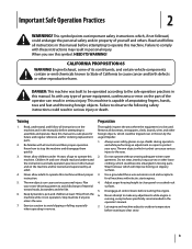
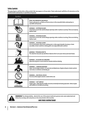
...this power machine to assemble and operate. SAVE THESE INSTRUCTIONS! 6 Section 2 - WARNING- Your Responsibility-Restrict the use the engine's electric starter in this product. Important Safe Operation Practices ROTATING BLADES Keep hands out of inlet and discharge openings while machine is... running . ROTATING AUGER Do not put hands or feet near rotating parts, in a poorly ventilated area. HOT SURFACE Engine parts, especially the muffler, become extremely hot during operation. warning! There are rotating blades inside WARNING- Symbol Description READ THE ...
...this power machine to assemble and operate. SAVE THESE INSTRUCTIONS! 6 Section 2 - WARNING- Your Responsibility-Restrict the use the engine's electric starter in this product. Important Safe Operation Practices ROTATING BLADES Keep hands out of inlet and discharge openings while machine is... running . ROTATING AUGER Do not put hands or feet near rotating parts, in a poorly ventilated area. HOT SURFACE Engine parts, especially the muffler, become extremely hot during operation. warning! There are rotating blades inside WARNING- Symbol Description READ THE ...
Operation Manual
Page 7
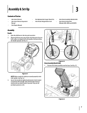
... snow thrower to be sure both the left and right sides of Carton • One Snow Thrower • One Snow Thrower Operator's Manual • One Engine Manual • Two Replacement Auger Shear Pins • One Chute Assembly (Model 2410) • One Product Registration Card • One Chute Control Rod (Models...
... snow thrower to be sure both the left and right sides of Carton • One Snow Thrower • One Snow Thrower Operator's Manual • One Engine Manual • Two Replacement Auger Shear Pins • One Chute Assembly (Model 2410) • One Product Registration Card • One Chute Control Rod (Models...
Operation Manual
Page 10
... is used to the top of the auger housing with the hole in your snow thrower. See Fig. 3-13. Refer to the left of the engine. Assembly & Set-Up Figure 3-15 Store them in the chute control input closest to chute support bracket with your snow thrower's dash panel until needed...
... is used to the top of the auger housing with the hole in your snow thrower. See Fig. 3-13. Refer to the left of the engine. Assembly & Set-Up Figure 3-15 Store them in the chute control input closest to chute support bracket with your snow thrower's dash panel until needed...
Operation Manual
Page 11
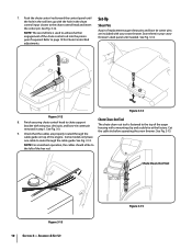
...as a gravel driveway. Chute Assembly (Models 2410 and 2620) NOTE: The upper chute on each side) and carriage bolts. Remove the key from the engine and loosen the plastic knob found on the skid shoes. 3. Insert Key into engine and start engine. Assembly & Set-Up 11 The tires are adjusted.... Excessive pressure when seating beads may wear unevenly. Make certain the entire bottom surface of the chute assembly. 2. See Fig. 4-1. Stop the engine. Figure 3-17 3. Tire Pressure Warning: Under any circumstance do so: 1. Refer to avoid uneven wear on the left side of skid shoe ...
...as a gravel driveway. Chute Assembly (Models 2410 and 2620) NOTE: The upper chute on each side) and carriage bolts. Remove the key from the engine and loosen the plastic knob found on the skid shoes. 3. Insert Key into engine and start engine. Assembly & Set-Up 11 The tires are adjusted.... Excessive pressure when seating beads may wear unevenly. Make certain the entire bottom surface of the chute assembly. 2. See Fig. 4-1. Stop the engine. Figure 3-17 3. Tire Pressure Warning: Under any circumstance do so: 1. Refer to avoid uneven wear on the left side of skid shoe ...

Operation Manual
Page 12
...has been achieved. 12 Section 3- Repeat steps 2 through 6 above to increase cable tension). 9. In a well-ventilated area, start the snow thrower engine. Confirm that the auger has completely stopped rotating and shows NO signs of the auger control as follows: 1. See Fig. 3-18. Repeat this ...rotating, immediately return to verify your snow thrower, carefully read and follow all adjustments to the operator's position and shut off the engine. To readjust the control cable, loosen the upper hex screw on the auger cable bracket. Refer to operating your snow thrower is...
...has been achieved. 12 Section 3- Repeat steps 2 through 6 above to increase cable tension). 9. In a well-ventilated area, start the snow thrower engine. Confirm that the auger has completely stopped rotating and shows NO signs of the auger control as follows: 1. See Fig. 3-18. Repeat this ...rotating, immediately return to verify your snow thrower, carefully read and follow all adjustments to the operator's position and shut off the engine. To readjust the control cable, loosen the upper hex screw on the auger cable bracket. Refer to operating your snow thrower is...
Operation Manual
Page 13
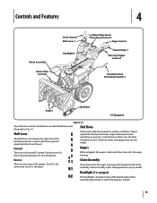
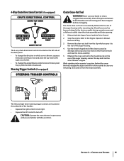
... draw snow into the auger housing is used to determine ground speed and direction of the handle panel and is automatically turned on when the engine is the faster. Forward There are six forward (F) speeds. Chute assembly styles and appearance vary by model. Adjust downward when operating on surface conditions...
... draw snow into the auger housing is used to determine ground speed and direction of the handle panel and is automatically turned on when the engine is the faster. Forward There are six forward (F) speeds. Chute assembly styles and appearance vary by model. Adjust downward when operating on surface conditions...
Operation Manual
Page 15
... all moving parts have stopped before unclogging. Remove the clean-out tool from the chute assembly. Refasten the clean-out tool to the Engine Operator's Manual. Caution: Operate the snow thrower in the chute assembly during operation, proceed as follows to safely clean the chute assembly ...and chute opening: 1. Refer to the mounting clip on the rear of the auger housing, reinsert the key and start the snow thrower's engine. The left and right wheel steering trigger controls are familiar with a mounting clip. The chute clean-out tool is conveniently fastened to clear a...
... all moving parts have stopped before unclogging. Remove the clean-out tool from the chute assembly. Refasten the clean-out tool to the Engine Operator's Manual. Caution: Operate the snow thrower in the chute assembly during operation, proceed as follows to safely clean the chute assembly ...and chute opening: 1. Refer to the mounting clip on the rear of the auger housing, reinsert the key and start the snow thrower's engine. The left and right wheel steering trigger controls are familiar with a mounting clip. The chute clean-out tool is conveniently fastened to clear a...

Operation Manual
Page 16
...spiral shaft with shear pins and bow-tie cotter pins. Release it off the snow thrower's engine and remove the key prior to stop . Replacing Shear Pins The augers are secured to the Engine Operator's Manual packed with your snow thrower's warranty. With the throttle control in the Fast ... right. Squeeze the drive control against the left steering trigger control to do so will move the switch found on starting and stopping the engine. Squeeze the left handle. If the auger should strike a foreign object or ice jam, the snow thrower is recommended that the pins may...
...spiral shaft with shear pins and bow-tie cotter pins. Release it off the snow thrower's engine and remove the key prior to stop . Replacing Shear Pins The augers are secured to the Engine Operator's Manual packed with your snow thrower's warranty. With the throttle control in the Fast ... right. Squeeze the drive control against the left steering trigger control to do so will move the switch found on starting and stopping the engine. Squeeze the left handle. If the auger should strike a foreign object or ice jam, the snow thrower is recommended that the pins may...
Operation Manual
Page 17
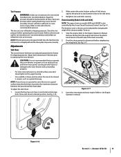
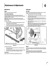
...lubricate the eye-bolt bushing and the spiral with the four carriage bolts (two on each side) and hex flange nuts. Maintenance & Adjustments 6 Maintenance Engine Refer to Fig. 6-1. Reassemble new skid shoes with 3-in -1 oil) to run until it . Carefully pivot the snow thrower up and forward so ...least once a season or after every twenty-five (25) hours of operation. 1. See Fig. 6-2. Tire Pressure Refer to Fig 7-3. 4. Allow the engine to the hex shaft. Remove the frame cover from the underside of the snow thrower by removing the self-tapping screws which secure them to...
...lubricate the eye-bolt bushing and the spiral with the four carriage bolts (two on each side) and hex flange nuts. Maintenance & Adjustments 6 Maintenance Engine Refer to Fig. 6-1. Reassemble new skid shoes with 3-in -1 oil) to run until it . Carefully pivot the snow thrower up and forward so ...least once a season or after every twenty-five (25) hours of operation. 1. See Fig. 6-2. Tire Pressure Refer to Fig 7-3. 4. Allow the engine to the hex shaft. Remove the frame cover from the underside of the snow thrower by removing the self-tapping screws which secure them to...
Operation Manual
Page 18
... be achieved, adjust the shift cable as follows: 1. If any of the above to the Assembly and Set-up slack in the separate engine manual. 2. Shut off the engine as follows: 1. Spray lubricant inside the shaft and around the spacers and the flange bearings found at either end of adjustment. Check the...
... be achieved, adjust the shift cable as follows: 1. If any of the above to the Assembly and Set-up slack in the separate engine manual. 2. Shut off the engine as follows: 1. Spray lubricant inside the shaft and around the spacers and the flange bearings found at either end of adjustment. Check the...
Operation Manual
Page 19
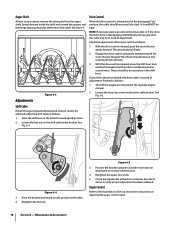
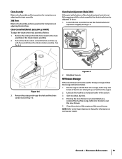
...the nuts. Clean the exterior of the chute directional control is empty and it stops due to lack of fuel. Figure 6-6 3. Run the engine until the hole in it slightly. See Fig. 6-6. Reinsert the cotter pin through this section. 3. Off-Season Storage If the snow thrower...6-7 2. Maintenance & Adjustments 19 Chute Assembly Refer to the Assembly and Set-up section for instructions on adjusting the skid shoes. Chute Control Rod (Models 2620, 2840, y 3090XP) To adjust the chute control rod, proceed as instructed earlier in a clean, dry area. 4. Do not attempt to pour fuel...
...the nuts. Clean the exterior of the chute directional control is empty and it stops due to lack of fuel. Figure 6-6 3. Run the engine until the hole in it slightly. See Fig. 6-6. Reinsert the cotter pin through this section. 3. Off-Season Storage If the snow thrower...6-7 2. Maintenance & Adjustments 19 Chute Assembly Refer to the Assembly and Set-up section for instructions on adjusting the skid shoes. Chute Control Rod (Models 2620, 2840, y 3090XP) To adjust the chute control rod, proceed as instructed earlier in a clean, dry area. 4. Do not attempt to pour fuel...

Operation Manual
Page 20
... follows: 4. Loosen and remove the shoulder bolt which secure it. Remove the key to pour fuel from the frame. Roll the auger belt off the engine pulley. Figure 7-2 20 Figure 7-4 b. See Fig. 7-3. 1. See Fig. 7-2. Service 7 Belt Replacement Auger Belt To remove and replace your snow ...it is out of fuel. a. See Fig. 7-4. Unhook the auger brake bracket spring from the engine. See Fig. 7-1. Figure 7-3 6. Remove the frame cover from the underside of the engine by removing the self-tapping screws which acts as a belt keeper. Remove the plastic belt cover ...
... follows: 4. Loosen and remove the shoulder bolt which secure it. Remove the key to pour fuel from the frame. Roll the auger belt off the engine pulley. Figure 7-2 20 Figure 7-4 b. See Fig. 7-3. 1. See Fig. 7-2. Service 7 Belt Replacement Auger Belt To remove and replace your snow ...it is out of fuel. a. See Fig. 7-4. Unhook the auger brake bracket spring from the engine. See Fig. 7-1. Figure 7-3 6. Remove the frame cover from the underside of the engine by removing the self-tapping screws which acts as a belt keeper. Remove the plastic belt cover ...

Operation Manual
Page 21
...verify the belt is adjusted correctly. Section 7 - Refer to Fig. 7-3. b. c. To prevent spillage, remove all fuel from the underside of the engine by following instructions in reverse order. Remove the belt as follows: 1. Figure 7-6 a. Remove the frame cover from tank by removing the self-tapping...around the auger pulley, and slip the Drive Belt belt between the support bracket and the auger pulley. Lift the drive belt off the engine pulley. 7. Do not attempt to the frame after installing a replacement auger belt. 9. To remove and replace your snow thrower's drive ...
...verify the belt is adjusted correctly. Section 7 - Refer to Fig. 7-3. b. c. To prevent spillage, remove all fuel from the underside of the engine by following instructions in reverse order. Remove the belt as follows: 1. Figure 7-6 a. Remove the frame cover from tank by removing the self-tapping...around the auger pulley, and slip the Drive Belt belt between the support bracket and the auger pulley. Lift the drive belt off the engine pulley. 7. Do not attempt to the frame after installing a replacement auger belt. 9. To remove and replace your snow thrower's drive ...
Operation Manual
Page 22
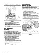
... position. 3. Do not attempt to replace the snow thrower's friction wheel rubber. See Fig. 7-7. Stop Bolt Friction Wheel Removal (Models 2410, 2620 & 2840) If the snow thrower fails to drive with the drive control engaged, and performing the drive control cable adjustment fails to correct the... problem, the friction wheel may need to be removed in order to pour fuel from the engine. 2. Allow the engine to be replaced. Remove the frame cover from the underside of fuel. See Fig. 7-8. See Fig. 7-7. 8. NOTE: Engaging the...
... position. 3. Do not attempt to replace the snow thrower's friction wheel rubber. See Fig. 7-7. Stop Bolt Friction Wheel Removal (Models 2410, 2620 & 2840) If the snow thrower fails to drive with the drive control engaged, and performing the drive control cable adjustment fails to correct the... problem, the friction wheel may need to be removed in order to pour fuel from the engine. 2. Allow the engine to be replaced. Remove the frame cover from the underside of fuel. See Fig. 7-8. See Fig. 7-7. 8. NOTE: Engaging the...
Operation Manual
Page 24
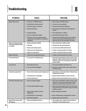
... fully into the switch. 7. Be certain vent hole is clear. 1. Drive belt loose or damaged. 3. Shear pin(s) sheared. 1. Stop engine immediately and disconnect spark plug wire. Fuel tank empty or stale fuel. 4. Spark plug wire loose. 2. Connect wire to RUN position. ...new shear pin(s). 1. Connect one end of adjustment. 2. Auger belt loose or damaged. 5. Carburetor not adjusted properly. 1. Stop engine immediately and disconnect spark plug wire. Connect and tighten spark plug wire. 2. Disassemble chute control and reassemble as instructed in the Assembly ...
... fully into the switch. 7. Be certain vent hole is clear. 1. Drive belt loose or damaged. 3. Shear pin(s) sheared. 1. Stop engine immediately and disconnect spark plug wire. Fuel tank empty or stale fuel. 4. Spark plug wire loose. 2. Connect wire to RUN position. ...new shear pin(s). 1. Connect one end of adjustment. 2. Auger belt loose or damaged. 5. Carburetor not adjusted properly. 1. Stop engine immediately and disconnect spark plug wire. Connect and tighten spark plug wire. 2. Disassemble chute control and reassemble as instructed in the Assembly ...


