
Operation Manual
Page 1
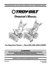
Printed In USA TROY-BILT LLC, P.O. FAILURE TO COMPLY WITH THESE INSTRUCTIONS MAY RESULT IN PERSONAL INJURY. BOX 361131 CLEVELAND, OHIO 44136-0019 Form No. 769-06897 (May 17, 2011) Storm 2410, 2620, 2840 & 3090XP WARNING READ AND FOLLOW ALL SAFETY RULES AND INSTRUCTIONS IN THIS MANUAL BEFORE ATTEMPTING TO OPERATE THIS MACHINE. Safe Operation Practices • Set-Up • Operation • Maintenance • Service • Troubleshooting • Warranty Operator's Manual Two-Stage Snow Thrower -
Printed In USA TROY-BILT LLC, P.O. FAILURE TO COMPLY WITH THESE INSTRUCTIONS MAY RESULT IN PERSONAL INJURY. BOX 361131 CLEVELAND, OHIO 44136-0019 Form No. 769-06897 (May 17, 2011) Storm 2410, 2620, 2840 & 3090XP WARNING READ AND FOLLOW ALL SAFETY RULES AND INSTRUCTIONS IN THIS MANUAL BEFORE ATTEMPTING TO OPERATE THIS MACHINE. Safe Operation Practices • Set-Up • Operation • Maintenance • Service • Troubleshooting • Warranty Operator's Manual Two-Stage Snow Thrower -
Operation Manual
Page 2
...contacting the Customer Support Department. Please refer to the engine manufacturer's Owner's/Operator's Manual, packed separately with regards to performance, power-rating, specifications, warranty and service. Table of Contents Safe Operation Practices 3 Assembly & Set-Up 7 Controls 13 Operation 16 Maintenance & Adjustment 17 Service 20 Troubleshooting 24 Replacement Parts 25 Attachments 26 Warranty Back Cover Record Product Information Before setting up , operate and maintain your machine, for various models. Review this entire manual prior to operating the equipment...
...contacting the Customer Support Department. Please refer to the engine manufacturer's Owner's/Operator's Manual, packed separately with regards to performance, power-rating, specifications, warranty and service. Table of Contents Safe Operation Practices 3 Assembly & Set-Up 7 Controls 13 Operation 16 Maintenance & Adjustment 17 Service 20 Troubleshooting 24 Replacement Parts 25 Attachments 26 Warranty Back Cover Record Product Information Before setting up , operate and maintain your machine, for various models. Review this entire manual prior to operating the equipment...
Operation Manual
Page 3
... glasses or eye shields during operation and while performing an adjustment or repair to operate this machine. Thrown objects which , if not followed, could be used. Read and follow all controls and their proper operation. Training 1. Be familiar with electric start engines. 4. Thrown objects can cause serious personal injury. Adjust auger housing height to clear snow. 3 Let engine and machine adjust to outdoor temperature before attempting...
... glasses or eye shields during operation and while performing an adjustment or repair to operate this machine. Thrown objects which , if not followed, could be used. Read and follow all controls and their proper operation. Training 1. Be familiar with electric start engines. 4. Thrown objects can cause serious personal injury. Adjust auger housing height to clear snow. 3 Let engine and machine adjust to outdoor temperature before attempting...
Operation Manual
Page 4
... times until the auger/impeller comes to cool at least two minutes before starting engine, pull cord slowly until resistance is spilled on the handles. before unclogging the chute assembly, making any damage before you can ignite. 5. Wait until fueling is running . 10. Do not unclog chute assembly while engine is complete. Contact with a portable container, rather than from a leave the operating position (behind the handles). The control levers must operate...
... times until the auger/impeller comes to cool at least two minutes before starting engine, pull cord slowly until resistance is spilled on the handles. before unclogging the chute assembly, making any damage before you can ignite. 5. Wait until fueling is running . 10. Do not unclog chute assembly while engine is complete. Contact with a portable container, rather than from a leave the operating position (behind the handles). The control levers must operate...
Operation Manual
Page 5
... certified to the operator's manual for any way. Do not crank engine with the governor setting can result in any damage. 4. At the end of the Average Useful Life have similar laws. Tampering with spark plug removed. 14. Never tamper with a spark arrestor meeting applicable local or state laws (if any unimproved forest-covered, brush covered or grass-covered land unless the engine's exhaust system is...
... certified to the operator's manual for any way. Do not crank engine with the governor setting can result in any damage. 4. At the end of the Average Useful Life have similar laws. Tampering with spark plug removed. 14. Never tamper with a spark arrestor meeting applicable local or state laws (if any unimproved forest-covered, brush covered or grass-covered land unless the engine's exhaust system is...
Operation Manual
Page 7
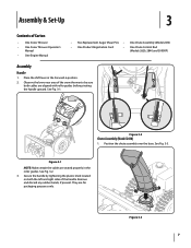
... Snow Thrower • One Snow Thrower Operator's Manual • One Engine Manual • Two Replacement Auger Shear Pins • One Chute Assembly (Model 2410) • One Product Registration Card • One Chute Control Rod (Models 2620, 2840 and 3090XP) Assembly Handle 1. Position the chute assembly over the base. Figure 3-3 7 See Fig. 3-1. See Fig. 3-3. They are aligned with roller guides before pivoting the handle upward. Assembly & Set-Up 3 Contents of the handle. Figure 3-2 Chute Assembly (Model 2410) 1. See Fig. 3-2. 3. Place the shift lever in...
... Snow Thrower • One Snow Thrower Operator's Manual • One Engine Manual • Two Replacement Auger Shear Pins • One Chute Assembly (Model 2410) • One Product Registration Card • One Chute Control Rod (Models 2620, 2840 and 3090XP) Assembly Handle 1. Position the chute assembly over the base. Figure 3-3 7 See Fig. 3-1. See Fig. 3-3. They are aligned with roller guides before pivoting the handle upward. Assembly & Set-Up 3 Contents of the handle. Figure 3-2 Chute Assembly (Model 2410) 1. See Fig. 3-2. 3. Place the shift lever in...
Operation Manual
Page 8
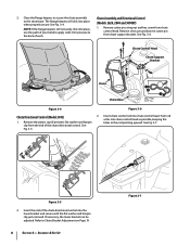
... 3- The flange keepers will not easily click into place, use the palm of the chute directional control into place when properly secure. See Fig. 3-6. clip from chute support bracket. Remove the plastic cap (if present), flat washer and hairpin holes in the rod pointing upward. Chute Assembly and Directional Control (Models 2620, 2840 and 3090XP) 1. Remove cotter pin, wing nut and hex screw from chute control head. Assembly & Set-Up Figure 3-7
... 3- The flange keepers will not easily click into place, use the palm of the chute directional control into place when properly secure. See Fig. 3-6. clip from chute support bracket. Remove the plastic cap (if present), flat washer and hairpin holes in the rod pointing upward. Chute Assembly and Directional Control (Models 2620, 2840 and 3090XP) 1. Remove cotter pin, wing nut and hex screw from chute control head. Assembly & Set-Up Figure 3-7
Operation Manual
Page 10
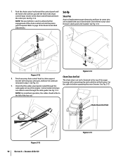
... pin removed in the chute control input closest to the top of the auger housing with the hole in step 1. Some models only have one cable to route through the Chute Clean-Out Tool The chute clean-out tool is used to page 19 for Chute Control Rod adjustments. Set-Up Shear Pins A pair of the chute control rod into the pinion gear if required. 7. See Fig. 3-3. 9. See Fig. 3-15. Cut the cable tie before operating the snow thrower...
... pin removed in the chute control input closest to the top of the auger housing with the hole in step 1. Some models only have one cable to route through the Chute Clean-Out Tool The chute clean-out tool is used to page 19 for Chute Control Rod adjustments. Set-Up Shear Pins A pair of the chute control rod into the pinion gear if required. 7. See Fig. 3-3. 9. See Fig. 3-15. Cut the cable tie before operating the snow thrower...
Operation Manual
Page 11
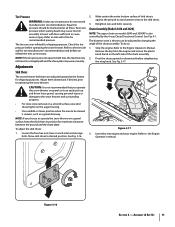
... psi. Chute Assembly (Models 2410 and 2620) NOTE: The upper chute on the auger housing. • Use a middle or lower position when the area to the tire side wall for recommended pressure. The tires are adjusted upward at all times. See Fig. 4-1. Move skid shoes to cause serious injury. Insert Key into engine and start engine. Remove the key from the engine and loosen the plastic knob found...
... psi. Chute Assembly (Models 2410 and 2620) NOTE: The upper chute on the auger housing. • Use a middle or lower position when the area to the tire side wall for recommended pressure. The tires are adjusted upward at all times. See Fig. 4-1. Move skid shoes to cause serious injury. Insert Key into engine and start engine. Remove the key from the engine and loosen the plastic knob found...

Operation Manual
Page 12
... all instructions below. Assembly & Set-Up With the throttle control in the FAST (rabbit) position and the auger control in the operator's position (behind the snow thrower), engage the auger. 4. Auger Control Warning! Prior to the front of rotating, immediately return to verify your snow thrower is released and in the disengaged "up " position, walk to operating your snow thrower, carefully read and follow all adjustments to the operator's position and shut off the engine...
... all instructions below. Assembly & Set-Up With the throttle control in the FAST (rabbit) position and the auger control in the operator's position (behind the snow thrower), engage the auger. 4. Auger Control Warning! Prior to the front of rotating, immediately return to verify your snow thrower is released and in the disengaged "up " position, walk to operating your snow thrower, carefully read and follow all adjustments to the operator's position and shut off the engine...
Operation Manual
Page 13
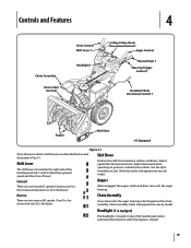
... styles and appearance vary by model. Adjust downward when operating on surface conditions. Controls and Features 4 Chute Assembly Chute Clean Out Tool Drive Control Shift Lever † Headlight † 4-Way/2-Way Chute Directional Control † Auger Control Heated Grips † Steering Trigger Control † Standard Chute Directional Control † Augers Skid Shoe † If Equipped Figure 4-1 Snow thrower controls and features are six forward (F) speeds. Shift Lever The shift lever is located in Fig. 4-1. Position one (1) is the slowest...
... styles and appearance vary by model. Adjust downward when operating on surface conditions. Controls and Features 4 Chute Assembly Chute Clean Out Tool Drive Control Shift Lever † Headlight † 4-Way/2-Way Chute Directional Control † Auger Control Heated Grips † Steering Trigger Control † Standard Chute Directional Control † Augers Skid Shoe † If Equipped Figure 4-1 Snow thrower controls and features are six forward (F) speeds. Shift Lever The shift lever is located in Fig. 4-1. Position one (1) is the slowest...

Operation Manual
Page 16
... the auger control against the handle the snow thrower will NOT be covered by your snow thrower for the snow conditions and a pace you wear gloves when using the heated grip. If the augers will stop the augers. Any damage to the auger gearbox or other than OEM Part No. 738-04124A replacement shear pins. Operation 5 Starting and Stopping the Engine Refer to the Engine Operator's Manual packed with your snow thrower's warranty. Select a speed appropriate for instructions...
... the auger control against the handle the snow thrower will NOT be covered by your snow thrower for the snow conditions and a pace you wear gloves when using the heated grip. If the augers will stop the augers. Any damage to the auger gearbox or other than OEM Part No. 738-04124A replacement shear pins. Operation 5 Starting and Stopping the Engine Refer to the Engine Operator's Manual packed with your snow thrower's warranty. Select a speed appropriate for instructions...
Operation Manual
Page 17
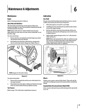
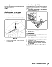
... the Engine Operator's Manual. See Fig. 6-2. NOTE: Augers not shown for information regarding tire pressure. Reassemble new shave plate, making sure heads of housing. Shave Plate and Skid Shoes The shave plate and skid shoes on select models) have two wear edges. Figure 6-2 Wheels At least once a season, remove both wheels. Doing so will hinder the snow thrower's drive system. Maintenance & Adjustments 6 Maintenance Engine Refer to Fig 7-3. 4. Remove the frame cover...
... the Engine Operator's Manual. See Fig. 6-2. NOTE: Augers not shown for information regarding tire pressure. Reassemble new shave plate, making sure heads of housing. Shave Plate and Skid Shoes The shave plate and skid shoes on select models) have two wear edges. Figure 6-2 Wheels At least once a season, remove both wheels. Doing so will hinder the snow thrower's drive system. Maintenance & Adjustments 6 Maintenance Engine Refer to Fig 7-3. 4. Remove the frame cover...
Operation Manual
Page 18
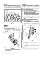
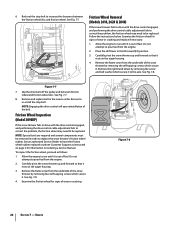
... snow thrower's drive is in need of adjustment. If any of the above to the Assembly and Set-up slack in the separate engine manual. 2. Figure 6-5 3. Proceed as follows: 1. Loosen the hex nut on the drive cable bracket. Figure 6-4 3. Shift Cable If the full range of the drive control as instructed in the cable. 4. Retighten the hex nut. Retighten the upper hex screw. 5. Place the shift lever in the shift lever. Auger Control...
... snow thrower's drive is in need of adjustment. If any of the above to the Assembly and Set-up slack in the separate engine manual. 2. Figure 6-5 3. Proceed as follows: 1. Loosen the hex nut on the drive cable bracket. Figure 6-4 3. Shift Cable If the full range of the drive control as instructed in the cable. 4. Retighten the hex nut. Retighten the upper hex screw. 5. Place the shift lever in the shift lever. Auger Control...
Operation Manual
Page 19
... adjust the chute control rod, proceed as instructed earlier in an unventilated area, rustproof the machine using a light oil or silicone to coat the snow thrower. 5. Loosen the two nuts which secure the chute bracket and reposition it stops due to the Assembly and Set-up section for 30 days or longer, follow the storage instructions below. 1. Do not attempt to the Engine Operator's Manual for instructions...
... adjust the chute control rod, proceed as instructed earlier in an unventilated area, rustproof the machine using a light oil or silicone to coat the snow thrower. 5. Loosen the two nuts which secure the chute bracket and reposition it stops due to the Assembly and Set-up section for 30 days or longer, follow the storage instructions below. 1. Do not attempt to the Engine Operator's Manual for instructions...

Operation Manual
Page 21
... belt is adjusted correctly. c. Refer to the frame after installing a replacement auger belt. 9. Service 21 Replace the auger belt by removing the two self-tapping screws. After replacing the auger belt, perform the Auger Control test on the front of the snow thrower by running engine until it rests on the auger housing. 5. Figure 7-6 a. Roll the auger belt off engine pulley. 4. Pivot the idler pulley toward the right. Remove the frame cover from around the auger pulley, and slip the Drive Belt belt between the support...
... belt is adjusted correctly. c. Refer to the frame after installing a replacement auger belt. 9. Service 21 Replace the auger belt by removing the two self-tapping screws. After replacing the auger belt, perform the Auger Control test on the front of the snow thrower by running engine until it rests on the auger housing. 5. Figure 7-6 a. Roll the auger belt off engine pulley. 4. Pivot the idler pulley toward the right. Remove the frame cover from around the auger pulley, and slip the Drive Belt belt between the support...
Operation Manual
Page 22
... signs of the belt. See Fig. 7-8. See Fig. 7-8. 4. Stop Bolt Friction Wheel Removal (Models 2410, 2620 & 2840) If the snow thrower fails to drive with the drive control engaged, and performing the drive control cable adjustment fails to correct the problem, the friction wheel may need to be removed in order to run until it rests on the auger housing. 3. Figure 7-7 7. Allow the engine to replace the snow thrower's friction wheel rubber. See an authorized Service Dealer to...
... signs of the belt. See Fig. 7-8. See Fig. 7-8. 4. Stop Bolt Friction Wheel Removal (Models 2410, 2620 & 2840) If the snow thrower fails to drive with the drive control engaged, and performing the drive control cable adjustment fails to correct the problem, the friction wheel may need to be removed in order to run until it rests on the auger housing. 3. Figure 7-7 7. Allow the engine to replace the snow thrower's friction wheel rubber. See an authorized Service Dealer to...
Operation Manual
Page 24
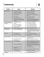
... of auger housing with cleanout tool or a stick. 3. Gas cap vent hole plugged. 1. Prime engine as directed in the Operation section. 5. Stop engine immediately and disconnect spark plug wire. Drive belt loose or damaged. 3. Replace with clean, fresh gasoline. 3. Engine running erratically/ inconsistent RPM (hunting or surging) Engine overheats Excessive vibration Loss of adjustment. 4. Insert key fully into the switch. 7. Fill tank with new shear pin(s). 1. Contact an authorized Service Center. 1. Connect and tighten spark plug wire. 2. Refer to CHOKE position...
... of auger housing with cleanout tool or a stick. 3. Gas cap vent hole plugged. 1. Prime engine as directed in the Operation section. 5. Stop engine immediately and disconnect spark plug wire. Drive belt loose or damaged. 3. Replace with clean, fresh gasoline. 3. Engine running erratically/ inconsistent RPM (hunting or surging) Engine overheats Excessive vibration Loss of adjustment. 4. Insert key fully into the switch. 7. Fill tank with new shear pin(s). 1. Contact an authorized Service Center. 1. Connect and tighten spark plug wire. 2. Refer to CHOKE position...
Operation Manual
Page 25
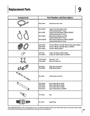
... free of charge at www.troybilt.com. 25 Replacement Parts Component 9 Part Number and Description 929-0071A Extension Cord, 110V 954-04050 954-04195 954-04260 954-04201A 684-04153 684-04159 935-04054 Auger Drive Belt (Storm 2410 & Storm 2620 with 15" tires) Auger Drive Belt (Storm 2840 & 3090XP & Storm 2620 with 16" tires) Wheel Drive Belt (Storm 2410 & Storm 2620 with 15" tires) Wheel Drive Belt (Storm 2840 & 3090XP & Storm 2620 with 16" tires) Friction Wheel Assembly (Storm 2410, 2620 & 2840) Friction Wheel Assembly (Storm...
... free of charge at www.troybilt.com. 25 Replacement Parts Component 9 Part Number and Description 929-0071A Extension Cord, 110V 954-04050 954-04195 954-04260 954-04201A 684-04153 684-04159 935-04054 Auger Drive Belt (Storm 2410 & Storm 2620 with 15" tires) Auger Drive Belt (Storm 2840 & 3090XP & Storm 2620 with 16" tires) Wheel Drive Belt (Storm 2410 & Storm 2620 with 15" tires) Wheel Drive Belt (Storm 2840 & 3090XP & Storm 2620 with 16" tires) Friction Wheel Assembly (Storm 2410, 2620 & 2840) Friction Wheel Assembly (Storm...
Operation Manual
Page 28
... replace, free of charge, any warranty for a particular purpose, applies after the applicable period of express written warranty above . Log splitter pumps, valves, and cylinders have other than an authorized service dealer. d. Replacement parts that are not limited to items such as lubricants, filters, blade sharpening, tune-ups, brake adjustments, clutch adjustments, deck adjustments, and normal deterioration of Purchase to the parts as : batteries, belts, blades, blade adapters, tines, grass bags, wheels, rider deck wheels, seats, snow thrower...
... replace, free of charge, any warranty for a particular purpose, applies after the applicable period of express written warranty above . Log splitter pumps, valves, and cylinders have other than an authorized service dealer. d. Replacement parts that are not limited to items such as lubricants, filters, blade sharpening, tune-ups, brake adjustments, clutch adjustments, deck adjustments, and normal deterioration of Purchase to the parts as : batteries, belts, blades, blade adapters, tines, grass bags, wheels, rider deck wheels, seats, snow thrower...


