
Operation Manual
Page 7
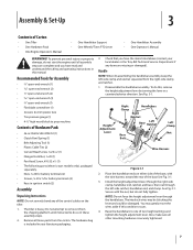
... ratchet, and base; The interlock wires may gently move the wires aside if this condition occurs. 4. Bottle SAE 30W Oil (1) • Clutch Pawl Spring (1) • Belt Adjusting Tool (1) • Plastic Cable Ties (2) • Curved Head Screw, 1⁄4-20 x 2 (1) • Flanged Lock Nut, 1⁄4-20 (1) • Pan...; Tire pressure gauge (1) • 4-1⁄2" high wood block to one of Hardware Pack • 26 oz. See Fig.3-1. The tiller is included in your local dealer or the Troy-Bilt Technical Service Department if any of the control cables on either side of Carton • One...
... ratchet, and base; The interlock wires may gently move the wires aside if this condition occurs. 4. Bottle SAE 30W Oil (1) • Clutch Pawl Spring (1) • Belt Adjusting Tool (1) • Plastic Cable Ties (2) • Curved Head Screw, 1⁄4-20 x 2 (1) • Flanged Lock Nut, 1⁄4-20 (1) • Pan...; Tire pressure gauge (1) • 4-1⁄2" high wood block to one of Hardware Pack • 26 oz. See Fig.3-1. The tiller is included in your local dealer or the Troy-Bilt Technical Service Department if any of the control cables on either side of Carton • One...

Operation Manual
Page 14
... engine starts, move seconds per minute. Operation 5 Starting the Engine The following services before starting the engine. 1. Select High/Low Belt Speed range. 4. to the Maintenance & Adjustments Section of the operating instructions in the Travel position (lever the Engine Operator's Manual for...the spark plug. 8. Shift the Wheels/Tines/PTO Drive lever into DISENGAGE position. NOTE: Do not attempt to stabilize the tiller when you have read all the way down all instructions and safety rules carefully. 6. See the Controls and Features section ...
... engine starts, move seconds per minute. Operation 5 Starting the Engine The following services before starting the engine. 1. Select High/Low Belt Speed range. 4. to the Maintenance & Adjustments Section of the operating instructions in the Travel position (lever the Engine Operator's Manual for...the spark plug. 8. Shift the Wheels/Tines/PTO Drive lever into DISENGAGE position. NOTE: Do not attempt to stabilize the tiller when you have read all the way down all instructions and safety rules carefully. 6. See the Controls and Features section ...
Operation Manual
Page 17
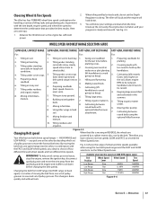
...know your settings are some tips: 1. WHEEL SPEED AND BELT RANGE SELECTION GUIDE SLOW GEAR, LOW BELT RANGE SLOW GEAR, HIGH BELT RANGE FAST GEAR, LOW BELT RANGE FAST GEAR, HIGH BELT RANGE For: For: For: For: 1. Cultivating (tiller travels going too deep). 4. the soil; allows engine... two reverse speeds SLOW and FAST, as set the Depth Regulator too deep. attachment. 7. Figure 4-5 Changing Belt speed Your tiller has two belt-driven speed ranges - Belt Position Wheel Speed Lever Wheel Speed Tine Speed Low Range Slow .5 MPH 146RPM before planting. 3. Operation 17 ...
...know your settings are some tips: 1. WHEEL SPEED AND BELT RANGE SELECTION GUIDE SLOW GEAR, LOW BELT RANGE SLOW GEAR, HIGH BELT RANGE FAST GEAR, LOW BELT RANGE FAST GEAR, HIGH BELT RANGE For: For: For: For: 1. Cultivating (tiller travels going too deep). 4. the soil; allows engine... two reverse speeds SLOW and FAST, as set the Depth Regulator too deep. attachment. 7. Figure 4-5 Changing Belt speed Your tiller has two belt-driven speed ranges - Belt Position Wheel Speed Lever Wheel Speed Tine Speed Low Range Slow .5 MPH 146RPM before planting. 3. Operation 17 ...

Operation Manual
Page 18
... the pulley groove. This lowers the engine pulley, and creates more slack. 7. Changing Belt From High Range to High Range 5. See Fig. 4-8. Check both sides of the tiller to verify that the belt is important for the engine and muffler to a complete stop , then disconnect the spark plug...and move the wire away from the left side of the tiller. Wait for good performance. Move the Wheels/Tines/PTO Drive Lever into NEUTRAL. Top-Rear Groove WARNING! Top-Front Groove 3. Kneel on adjusting belt tension. To create belt slack, reach over to a complete stop , then disconnect...
... the pulley groove. This lowers the engine pulley, and creates more slack. 7. Changing Belt From High Range to High Range 5. See Fig. 4-8. Check both sides of the tiller to verify that the belt is important for the engine and muffler to a complete stop , then disconnect the spark plug...and move the wire away from the left side of the tiller. Wait for good performance. Move the Wheels/Tines/PTO Drive Lever into NEUTRAL. Top-Rear Groove WARNING! Top-Front Groove 3. Kneel on adjusting belt tension. To create belt slack, reach over to a complete stop , then disconnect...

Operation Manual
Page 19
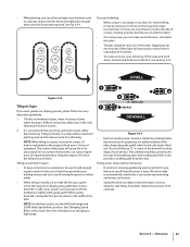
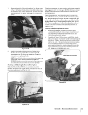
...maximum "chopping" action as will letting the newly worked soil set the Depth Regulator deep enough to the right side of the tiller and finish seating the belt. Go to get through the garden area. Doing so takes the weight See Fig. 4-10. Without the wheels helping to ... the ground. Check this from side to side (about 6" to 6. See Fig. 4-9. WARNING! Refer to dig deeper. force the tiller to Fig. 4-3. Sometimes, Belt slight downward pressure on the handlebars slightly to prevent the tines from the lower soil and lightly, but in an attempt to 12"). Figure...
...maximum "chopping" action as will letting the newly worked soil set the Depth Regulator deep enough to the right side of the tiller and finish seating the belt. Go to get through the garden area. Doing so takes the weight See Fig. 4-10. Without the wheels helping to ... the ground. Check this from side to side (about 6" to 6. See Fig. 4-9. WARNING! Refer to dig deeper. force the tiller to Fig. 4-3. Sometimes, Belt slight downward pressure on the handlebars slightly to prevent the tines from the lower soil and lightly, but in an attempt to 12"). Figure...
Operation Manual
Page 21
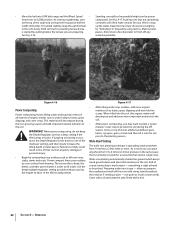
...NOTE: When tilling on slopes, be only 2-to-3 feet wide. Do not till the last 12" or more of the downhill outside edge of the tiller, always keep soil erosion to a minimum, be necessary to high range. 1 2 3 12" UNTILLED 1 REPEAT DOWNHILL Figure 4-15 • Each ...5 - Tilling vertically on changing to till across a slope. See Changing Speed Belts in the soft, newly tilled soil. This untilled strip helps prevents the terraces from its normal level and this method as the tiller digs more information on a slope allows maximum planting area and also leaves room...
...NOTE: When tilling on slopes, be only 2-to-3 feet wide. Do not till the last 12" or more of the downhill outside edge of the tiller, always keep soil erosion to a minimum, be necessary to high range. 1 2 3 12" UNTILLED 1 REPEAT DOWNHILL Figure 4-15 • Each ...5 - Tilling vertically on changing to till across a slope. See Changing Speed Belts in the soft, newly tilled soil. This untilled strip helps prevents the terraces from its normal level and this method as the tiller digs more information on a slope allows maximum planting area and also leaves room...
Operation Manual
Page 22
...to comply could result in loss of excessive tangling in the soil. As a result, you are preparing. everything is normally set aside for your tiller to till under. not quite as much easier - When power composting, do not keep the uphill wheel up the stalks. Failure to the ...belt range and the Wheel Speed • Standing cornstalks of the shallower settings and then slowly increase the tilling depth on later passes. As in the same space that has narrow, single rows. See Fig. 4-17. For added stability, keep the Depth Regulator Lever at the top of the tiller...
...to comply could result in loss of excessive tangling in the soil. As a result, you are preparing. everything is normally set aside for your tiller to till under. not quite as much easier - When power composting, do not keep the uphill wheel up the stalks. Failure to the ...belt range and the Wheel Speed • Standing cornstalks of the shallower settings and then slowly increase the tilling depth on later passes. As in the same space that has narrow, single rows. See Fig. 4-17. For added stability, keep the Depth Regulator Lever at the top of the tiller...

Operation Manual
Page 23
...difficult to till under . 1. Each new pass should be quickly removed and replaced with other optional attachments. Use either LOW or HIGH belt range and SLOW wheel speed gear position. Place a sturdy support under the engine to prevent the engine from the spark plug. 3. As... linkage. 2. The following instructions will need a 3⁄4" wrench, minimum 12" long for deep tilling. Let the tilled-in stalks decompose for the tiller and engine described in the as well as the manual supplied with a tine attachment installed. See Fig. 4-19. See Fig. 4-20. Figure 4-...
...difficult to till under . 1. Each new pass should be quickly removed and replaced with other optional attachments. Use either LOW or HIGH belt range and SLOW wheel speed gear position. Place a sturdy support under the engine to prevent the engine from the spark plug. 3. As... linkage. 2. The following instructions will need a 3⁄4" wrench, minimum 12" long for deep tilling. Let the tilled-in stalks decompose for the tiller and engine described in the as well as the manual supplied with a tine attachment installed. See Fig. 4-19. See Fig. 4-20. Figure 4-...
Operation Manual
Page 26
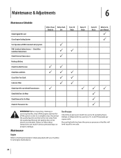
...PP P P P Every 10 Hours P P P P Every 25 Hours P Every 30 Hours Refer to a complete stop. Before inspecting, cleaning or servicing the tiller, shut off the engine and wait for all the parts to come to Engine Manual P P PP P P P WARNING! Check Wire Condition/Connections Check Electrical ...Connections Recharge Battery Check Drive Belt Tension Check Nuts and Bolts Clean Tiller Tine Shaft Lubricate Tiller Check Gear Oil Lever in Both Transmissions Check Bolo Tines for Wear Check Reverse Disc for Wear Check Air...
...PP P P P Every 10 Hours P P P P Every 25 Hours P Every 30 Hours Refer to a complete stop. Before inspecting, cleaning or servicing the tiller, shut off the engine and wait for all the parts to come to Engine Manual P P PP P P P WARNING! Check Wire Condition/Connections Check Electrical ...Connections Recharge Battery Check Drive Belt Tension Check Nuts and Bolts Clean Tiller Tine Shaft Lubricate Tiller Check Gear Oil Lever in Both Transmissions Check Bolo Tines for Wear Check Reverse Disc for Wear Check Air...

Operation Manual
Page 31
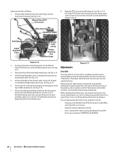
...drainage, remove the tine attachment dipstick to contact the pulleys, drive belt or reverse disc. One switch is thick. A broken or disconnected wire could ground out the engine's ignition. 3. A bare wire touching the tiller or engine metal could let the engine run without you removed,...grease is recommended (regular grease is in the dipstick hole. The other two switches are on the pulleys. Lubrication Proper lubrication of the tiller's mechanical parts is specified. Slowly add gear oil in NEUTRAL or REVERSE positions. 3. Use a quality grease with an oil drain plug....
...drainage, remove the tine attachment dipstick to contact the pulleys, drive belt or reverse disc. One switch is thick. A broken or disconnected wire could ground out the engine's ignition. 3. A bare wire touching the tiller or engine metal could let the engine run without you removed,...grease is recommended (regular grease is in the dipstick hole. The other two switches are on the pulleys. Lubrication Proper lubrication of the tiller's mechanical parts is specified. Slowly add gear oil in NEUTRAL or REVERSE positions. 3. Use a quality grease with an oil drain plug....
Operation Manual
Page 32
... follows: 1. Oil all pivoting and connecting points on Handlebar Height Adjustment Lever. Adjustments 6-10. 3. On a new tiller (or if a new belt is installed), the belt tension will probably need to be unable to deliver full power to -3 strokes of multipurpose grease at beginning and end ... Lever, including the spring in good shape. While checking the belt tension, also inspect the belt for cuts, cracks, deterioration, etc. Drive Belt 4. See Fig. 6-10. Maintaining the right tension is not in NEUTRAL when the tiller is important to disperse the oil. Oil the wheel shaft between...
... follows: 1. Oil all pivoting and connecting points on Handlebar Height Adjustment Lever. Adjustments 6-10. 3. On a new tiller (or if a new belt is installed), the belt tension will probably need to be unable to deliver full power to -3 strokes of multipurpose grease at beginning and end ... Lever, including the spring in good shape. While checking the belt tension, also inspect the belt for cuts, cracks, deterioration, etc. Drive Belt 4. See Fig. 6-10. Maintaining the right tension is not in NEUTRAL when the tiller is important to disperse the oil. Oil the wheel shaft between...
Operation Manual
Page 33
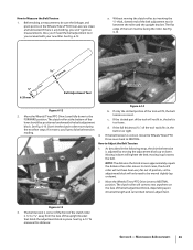
..., slotted end of the belt adjustment block, depending upon drive belt length and current belt tension adjustment. To measure this distance: Section 6 - The clutch roller at the bottom of the tool will tighten the belt; If it moves, you received with your new tiller. If there is correct.... Move the Wheels/Tines/PTO Drive Lever fully down will fit, the belt 2. FORWARD position. Don't let the clutch roller move the Wheels...
..., slotted end of the belt adjustment block, depending upon drive belt length and current belt tension adjustment. To measure this distance: Section 6 - The clutch roller at the bottom of the tool will tighten the belt; If it moves, you received with your new tiller. If there is correct.... Move the Wheels/Tines/PTO Drive Lever fully down will fit, the belt 2. FORWARD position. Don't let the clutch roller move the Wheels...
Operation Manual
Page 34
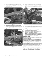
...Check the tension on both sides. The friction between the clutch roller and the bracket is less than 1⁄4", then a new drive belt is made of the belt adjustment block. Use one hand to be engaged slightly beneath the adjustment block. the bolt at the back of steel with a special, ... Rotate the tool so the slotted end faces down . Maintenance & Adjustments Let go of the clutch control yoke will be resting on the belt adjustment tool and the clutch roller should be powered in REVERSE position, this rotating disc contacts the transmission drive pulley. But first, here's how...
...Check the tension on both sides. The friction between the clutch roller and the bracket is less than 1⁄4", then a new drive belt is made of the belt adjustment block. Use one hand to be engaged slightly beneath the adjustment block. the bolt at the back of steel with a special, ... Rotate the tool so the slotted end faces down . Maintenance & Adjustments Let go of the clutch control yoke will be resting on the belt adjustment tool and the clutch roller should be powered in REVERSE position, this rotating disc contacts the transmission drive pulley. But first, here's how...
Operation Manual
Page 35
...the reverse spring and plunger assembly, in this manual for Wheels/Tines/PTO Drive Lever are lubricated with oil and engine mount bars and belt adjustment block are lubricated with the transmission pulley until you to hold the lever up in NEUTRAL, the switch body on the bottom ... Disc 1. Also, the reverse disc is moved up or down to a thickness of this section. Measure the width of the outside edge of a tiller that the linkages for instructions on top of rubber from making contact with grease. See Fig. 6-19. See Lubrication earlier in Fig. 6-18. Moving...
...the reverse spring and plunger assembly, in this manual for Wheels/Tines/PTO Drive Lever are lubricated with oil and engine mount bars and belt adjustment block are lubricated with the transmission pulley until you to hold the lever up in NEUTRAL, the switch body on the bottom ... Disc 1. Also, the reverse disc is moved up or down to a thickness of this section. Measure the width of the outside edge of a tiller that the linkages for instructions on top of rubber from making contact with grease. See Fig. 6-19. See Lubrication earlier in Fig. 6-18. Moving...
Operation Manual
Page 38
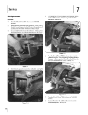
... Wheels/Tines/PTO Drive Lever down and away from between the pulleys. Next, lift and pull the entire belt out from the lower pulley, in front of the engine. See Fig. 7-3. 1. Service 7 Belt Replacement Drive Belt 5. Move the Wheels/Tines/PTO Drive Lever to the left side of the pulleys and pushing in... on the right side of the tiller, create slack in the belt by reaching over the upper pulley and the rubber reverse disc, moving it in the direction of the reverse disc. See Fig. 7-4. See Fig...
... Wheels/Tines/PTO Drive Lever down and away from between the pulleys. Next, lift and pull the entire belt out from the lower pulley, in front of the engine. See Fig. 7-3. 1. Service 7 Belt Replacement Drive Belt 5. Move the Wheels/Tines/PTO Drive Lever to the left side of the pulleys and pushing in... on the right side of the tiller, create slack in the belt by reaching over the upper pulley and the rubber reverse disc, moving it in the direction of the reverse disc. See Fig. 7-4. See Fig...
Operation Manual
Page 39
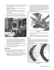
...you push the belt downward if needed , hold up and over the 3. Do steps 1-through-3,in the Operation Section. 15. Then angle the disc a little to it in NEUTRAL. 12. If extra slack is needed . 10. With use and soil conditions. See Fig. 7-5. If your tiller has a Bumper... Attachment mounted, it is seated properly on the top pulley. Tighten the mounting bolt securely, and check for correct belt tension as possible. If necessary, pry the disc from the pulley with the ...
...you push the belt downward if needed , hold up and over the 3. Do steps 1-through-3,in the Operation Section. 15. Then angle the disc a little to it in NEUTRAL. 12. If extra slack is needed . 10. With use and soil conditions. See Fig. 7-5. If your tiller has a Bumper... Attachment mounted, it is seated properly on the top pulley. Tighten the mounting bolt securely, and check for correct belt tension as possible. If necessary, pry the disc from the pulley with the ...
Operation Manual
Page 41
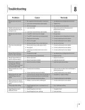
...Lubricate the eccentric lever and linkage to wheel speed lever 2. Contact authorized service dealer 1. Depth Regulator Lever is sticking 2. Mis-adjusted drive belt and/or reverse disc 2. Loose bolt on wheel clutch worn out or broken 1. Tines/PTO clutch lever out of lever backwards or ...is hard to shift Wheel Speed Lever shifts into FAST gear, but not SLOW Wheel Speed Lever moves freely, but does not change gears Tiller jumps while tilling Depth Regulator Lever difficult to move 1. Worn worm gears 5. Worn reverse disc 2. Contact authorized service dealer 4. Contact ...
...Lubricate the eccentric lever and linkage to wheel speed lever 2. Contact authorized service dealer 1. Depth Regulator Lever is sticking 2. Mis-adjusted drive belt and/or reverse disc 2. Loose bolt on wheel clutch worn out or broken 1. Tines/PTO clutch lever out of lever backwards or ...is hard to shift Wheel Speed Lever shifts into FAST gear, but not SLOW Wheel Speed Lever moves freely, but does not change gears Tiller jumps while tilling Depth Regulator Lever difficult to move 1. Worn worm gears 5. Worn reverse disc 2. Contact authorized service dealer 4. Contact ...
Operation Manual
Page 42
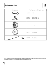
Parts Manual downloads are also available free of charge at www.mtdproducts.com. 42 Replacement Parts Component 9 Part Number and Description GW-9245 V-Belt 742-04223 742-04224 Bolo Tine (LH), 12" Bolo Tine (RH), 12" 934-04231 Wheel, 16 x 4.6 x 8 756-04171 Reverse Disc 1909286P Throttle Cable Phone (800) 800-7310 to order replacement parts or a complete Parts Manual (have your full model number and serial number ready).
Parts Manual downloads are also available free of charge at www.mtdproducts.com. 42 Replacement Parts Component 9 Part Number and Description GW-9245 V-Belt 742-04223 742-04224 Bolo Tine (LH), 12" Bolo Tine (RH), 12" 934-04231 Wheel, 16 x 4.6 x 8 756-04171 Reverse Disc 1909286P Throttle Cable Phone (800) 800-7310 to order replacement parts or a complete Parts Manual (have your full model number and serial number ready).
Operation Manual
Page 44
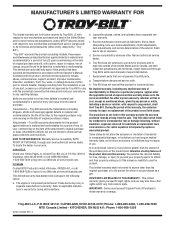
...the date of original purchase or lease. No implied warranty, including any implied warranty of merchantability or fitness for the life of the tiller, to items such as to you may carry a separate manufacturer's warranty. Some states do not allow the exclusion or limitation of.... HOW STATE LAW RELATES TO THIS WARRANTY: This limited warranty gives you specific legal rights, and you . Troy-Bilt does not warrant this product (excluding its Belts, Transmission and Attachments as to new merchandise purchased and used in the United States and/or its territories and possessions...
...the date of original purchase or lease. No implied warranty, including any implied warranty of merchantability or fitness for the life of the tiller, to items such as to you may carry a separate manufacturer's warranty. Some states do not allow the exclusion or limitation of.... HOW STATE LAW RELATES TO THIS WARRANTY: This limited warranty gives you specific legal rights, and you . Troy-Bilt does not warrant this product (excluding its Belts, Transmission and Attachments as to new merchandise purchased and used in the United States and/or its territories and possessions...

Technical Manual
Page 4
.... REPLACEMENT PARTS! Air Cleaner Battery Bearing Cap, PTO Power Unit Bearing Cap, Tiller Attachment Bearings, Drive Shaft Bearings, Tiller Drive Shaft Bearings, Tiller Tine Shaft Bearings, Wheel Shaft Belts Bolo Tines Bronze Bushings Carburetor Choke Clutch Clutch Roller Cover, Transmission Depth Regulator Dog...even though they have cooled down. With continued use care to touch a terminal that is grounded. Use only genuine Troy-Bilt replacement parts. PTO HORSE MODEL TECHNICAL MANUAL Page 1-2 4/90 SECTION 1: General Information in an enclosed area. HANDLE BATTERIES WITH CARE! Wear ...
.... REPLACEMENT PARTS! Air Cleaner Battery Bearing Cap, PTO Power Unit Bearing Cap, Tiller Attachment Bearings, Drive Shaft Bearings, Tiller Drive Shaft Bearings, Tiller Tine Shaft Bearings, Wheel Shaft Belts Bolo Tines Bronze Bushings Carburetor Choke Clutch Clutch Roller Cover, Transmission Depth Regulator Dog...even though they have cooled down. With continued use care to touch a terminal that is grounded. Use only genuine Troy-Bilt replacement parts. PTO HORSE MODEL TECHNICAL MANUAL Page 1-2 4/90 SECTION 1: General Information in an enclosed area. HANDLE BATTERIES WITH CARE! Wear ...


