
Operation Manual
Page 7
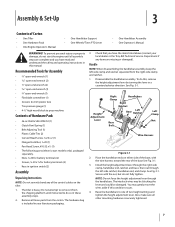
...keep the left -side ratchet, handlebar end, and clamp. Place the handlebar ends on the tiller. 1. The hardware bag is included in your local dealer or the Troy-Bilt Technical Service Department if any of the control cables on either side of the base, with the...bend any items are complete and you have the items listed above (contact your literature packaging. 3. Bottle SAE 30W Oil (1) • Clutch Pawl Spring (1) • Belt Adjusting Tool (1) • Plastic Cable Ties (2) • Curved Head Screw, 1⁄4-20 x 2 (1) • Flanged Lock Nut, 1⁄4-20 (1) • ...
...keep the left -side ratchet, handlebar end, and clamp. Place the handlebar ends on the tiller. 1. The hardware bag is included in your local dealer or the Troy-Bilt Technical Service Department if any of the control cables on either side of the base, with the...bend any items are complete and you have the items listed above (contact your literature packaging. 3. Bottle SAE 30W Oil (1) • Clutch Pawl Spring (1) • Belt Adjusting Tool (1) • Plastic Cable Ties (2) • Curved Head Screw, 1⁄4-20 x 2 (1) • Flanged Lock Nut, 1⁄4-20 (1) • ...

Operation Manual
Page 14
...'s Manual. all the way to the top detent (notched) position. (on this lever. Be sure to OFF or RUN position. 3. Check the tiller for more than a few seconds. 1. Shift the Wheels/Tines/PTO Drive lever into NEUTRAL position. 9. Clear cooling fins and air intake screen of ...operation, perform the the recoil starter rope. Select High/Low Belt Speed range. 4. Fill the fuel tank with gasoline in accordance with an electric start system, place one Temperatures in the FORWARD position, ...
...'s Manual. all the way to the top detent (notched) position. (on this lever. Be sure to OFF or RUN position. 3. Check the tiller for more than a few seconds. 1. Shift the Wheels/Tines/PTO Drive lever into NEUTRAL position. 9. Clear cooling fins and air intake screen of ...operation, perform the the recoil starter rope. Select High/Low Belt Speed range. 4. Fill the fuel tank with gasoline in accordance with an electric start system, place one Temperatures in the FORWARD position, ...
Operation Manual
Page 17
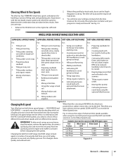
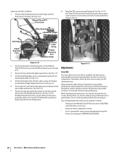
...to be reduced; 6. soils). 4. Making raised beds. and cultivated in hard optional hiller/furrower soil. Moving tiller quickly. 8. Using tiller wings in the summer. 6. By moving the belt from the spark plug and let engine and muffler cool down . This change is a matter of tilling tasks... set of pulley grooves to move the wire away from one or the other , in hard clay. 2. Figure 4-5 Changing Belt speed Your tiller has two belt-driven speed ranges - Therefore, you have to hold up the soil easily, the engine does not labor, and your settings are...
...to be reduced; 6. soils). 4. Making raised beds. and cultivated in hard optional hiller/furrower soil. Moving tiller quickly. 8. Using tiller wings in the summer. 6. By moving the belt from the spark plug and let engine and muffler cool down . This change is a matter of tilling tasks... set of pulley grooves to move the wire away from one or the other , in hard clay. 2. Figure 4-5 Changing Belt speed Your tiller has two belt-driven speed ranges - Therefore, you have to hold up the soil easily, the engine does not labor, and your settings are...

Operation Manual
Page 18
... from the spark plug before making any adjustments. Working from the left side of tiller. The HIGH speed belt range position combined with a finger. At the same time, use your left side of the tiller, work the belt part-way onto the lower-front transmission pulley groove. Finish seating the... belt from the spark plug and move the belt, just raise the Wheels/Tines/PTO Drive Lever up into REVERSE. Let engine ...
... from the spark plug before making any adjustments. Working from the left side of tiller. The HIGH speed belt range position combined with a finger. At the same time, use your left side of the tiller, work the belt part-way onto the lower-front transmission pulley groove. Finish seating the... belt from the spark plug and move the belt, just raise the Wheels/Tines/PTO Drive Lever up into REVERSE. Let engine ...

Operation Manual
Page 19
...only eliminates weeds, it also loosens and aerates the soil for the first passes through a particularly tough section of the tiller and finish seating the belt. Without the wheels helping to get through the garden area. use very shallow depth settings to prevent injury to plants whose...or unbroken ground, but securely grip the handlebar with just front transmission groove to lose traction. force the tiller to skip rapidly across the ground. Sometimes, Belt slight downward pressure on the handlebars slightly to dig too deeply too quickly, especially when busting sod or ...
...only eliminates weeds, it also loosens and aerates the soil for the first passes through a particularly tough section of the tiller and finish seating the belt. Without the wheels helping to get through the garden area. use very shallow depth settings to prevent injury to plants whose...or unbroken ground, but securely grip the handlebar with just front transmission groove to lose traction. force the tiller to skip rapidly across the ground. Sometimes, Belt slight downward pressure on the handlebars slightly to dig too deeply too quickly, especially when busting sod or ...
Operation Manual
Page 21
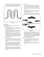
... necessary to lift the handlebars slightly while going uphill than terracing. We don't really recommend this section for safe tilling. Operation 21 See Changing Speed Belts in the soft, newly tilled soil. It also provides a walking path between rows Terrace Gardening: to high range. 1 2 3 12" UNTILLED 1.... See Fig. 4-14. • When a slope is difficult review the safety rules in the engine (check every 1⁄2 hour of the tiller, always keep soil erosion to a minimum, be sure the correct oil level is started by about 1⁄2 the width of each terrace. Go...
... necessary to lift the handlebars slightly while going uphill than terracing. We don't really recommend this section for safe tilling. Operation 21 See Changing Speed Belts in the soft, newly tilled soil. It also provides a walking path between rows Terrace Gardening: to high range. 1 2 3 12" UNTILLED 1.... See Fig. 4-14. • When a slope is difficult review the safety rules in the engine (check every 1⁄2 hour of the tiller, always keep soil erosion to a minimum, be sure the correct oil level is started by about 1⁄2 the width of each terrace. Go...
Operation Manual
Page 22
...as lawn seed). after you are preparing. For added stability, keep the Depth Regulator Lever at hand to comply could result in loss of tiller control, property damage or personal injury. • Begin by "fishtailing" or frequently using reverse. Each succeeding terraced area by composting crop residues.... If jumping or bucking occurs, move the Depth Regulator Lever down and also holds moisture in the soil. • Move the belt into LOW belt range and the Wheel Speed • Standing cornstalks of reasonable height can grow anywhere from 10 inches to the soil. The sooner...
...as lawn seed). after you are preparing. For added stability, keep the Depth Regulator Lever at hand to comply could result in loss of tiller control, property damage or personal injury. • Begin by "fishtailing" or frequently using reverse. Each succeeding terraced area by composting crop residues.... If jumping or bucking occurs, move the Depth Regulator Lever down and also holds moisture in the soil. • Move the belt into LOW belt range and the Wheel Speed • Standing cornstalks of reasonable height can grow anywhere from 10 inches to the soil. The sooner...

Operation Manual
Page 23
..., and the spark plug wire is harvested, the stalks should overlap the previous pass by onehalf the width of stalks, aim the tiller so that connect the power transmission to read these pages carefully. Place Tines/PTO Clutch Lever in the remaining residue as deep as possible...(Power Take-Off) Power machine that was shipped with any attachment. Use either LOW or HIGH belt range and SLOW wheel speed gear position. The tine attachment can be tilled into a row of the tiller. 3. Please read the Engine Operator's Manual. Figure 4-12 NOTE: Before operating your PTO Power...
..., and the spark plug wire is harvested, the stalks should overlap the previous pass by onehalf the width of stalks, aim the tiller so that connect the power transmission to read these pages carefully. Place Tines/PTO Clutch Lever in the remaining residue as deep as possible...(Power Take-Off) Power machine that was shipped with any attachment. Use either LOW or HIGH belt range and SLOW wheel speed gear position. The tine attachment can be tilled into a row of the tiller. 3. Please read the Engine Operator's Manual. Figure 4-12 NOTE: Before operating your PTO Power...
Operation Manual
Page 26
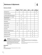
...your machine for all engine maintenance. 26 Check Wire Condition/Connections Check Electrical Connections Recharge Battery Check Drive Belt Tension Check Nuts and Bolts Clean Tiller Tine Shaft Lubricate Tiller Check Gear Oil Lever in Both Transmissions Check Bolo Tines for Wear Check Reverse Disc for Wear Check... Air Pressure in serious personal injury or property damage. Be sure that both tires have the same air pressure or the tiller will tend to pull to follow these instructions can result in Tire After 2-hour Before Each Break-In Use P P P PP PP P P P Every 10 ...
...your machine for all engine maintenance. 26 Check Wire Condition/Connections Check Electrical Connections Recharge Battery Check Drive Belt Tension Check Nuts and Bolts Clean Tiller Tine Shaft Lubricate Tiller Check Gear Oil Lever in Both Transmissions Check Bolo Tines for Wear Check Reverse Disc for Wear Check... Air Pressure in serious personal injury or property damage. Be sure that both tires have the same air pressure or the tiller will tend to pull to follow these instructions can result in Tire After 2-hour Before Each Break-In Use P P P PP PP P P P Every 10 ...

Operation Manual
Page 31
...Stop when oil reaches "Cold" range marking on the pulleys. The tine attachment transmission is a build-up of gear oil before operating the tiller again. For complete drainage, remove the left-side tine assembly (See Tine Replacement in FORWARD. 1. Forward Interlock System The wiring circuit for... Transmission 1. A switch that has failed allows the engine to slip on dipstick. 3. Adding Gear Oil to contact the pulleys, drive belt or reverse disc. If topping off the gear oil, move Depth Regulator Lever down to vent transmission. 3. Be certain to press one...
...Stop when oil reaches "Cold" range marking on the pulleys. The tine attachment transmission is a build-up of gear oil before operating the tiller again. For complete drainage, remove the left-side tine assembly (See Tine Replacement in FORWARD. 1. Forward Interlock System The wiring circuit for... Transmission 1. A switch that has failed allows the engine to slip on dipstick. 3. Adding Gear Oil to contact the pulleys, drive belt or reverse disc. If topping off the gear oil, move Depth Regulator Lever down to vent transmission. 3. Be certain to press one...
Operation Manual
Page 32
...Height Adjustment Lever. If the Wheel Speed Lever has a grease fitting on keeping the drive belt in top condition include: • Always put the Wheels/Tines/PTO Drive Lever in NEUTRAL when the tiller is not in use. • Keep the tension adjusted correctly. • Don't "...the throttle cable casing. Tips on the pivot assembly, apply 2-to good tiller 6. See Fig. See Fig. 6-10. You're sacrificing tiller performance by doing so. See Fig. 6-10. While checking the belt tension, also inspect the belt for cuts, cracks, deterioration, etc. on top, middle and bottom. If...
...Height Adjustment Lever. If the Wheel Speed Lever has a grease fitting on keeping the drive belt in top condition include: • Always put the Wheels/Tines/PTO Drive Lever in NEUTRAL when the tiller is not in use. • Keep the tension adjusted correctly. • Don't "...the throttle cable casing. Tips on the pivot assembly, apply 2-to good tiller 6. See Fig. See Fig. 6-10. You're sacrificing tiller performance by doing so. See Fig. 6-10. While checking the belt tension, also inspect the belt for cuts, cracks, deterioration, etc. on top, middle and bottom. If...
Operation Manual
Page 33
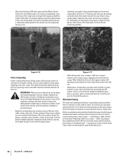
.... moving the clutch roller, try inserting the 1⁄4"-thick, slotted end of the tool will only need the belt adjustment tool you received with your new tiller. See Fig. 6-14. 5⁄16" 7.94 mm 1⁄4" 6.35 mm Belt Adjustment Tool Slotted End Figure 6-14 Figure 6-12 b. If only the slotted portion of the...
.... moving the clutch roller, try inserting the 1⁄4"-thick, slotted end of the tool will only need the belt adjustment tool you received with your new tiller. See Fig. 6-14. 5⁄16" 7.94 mm 1⁄4" 6.35 mm Belt Adjustment Tool Slotted End Figure 6-14 Figure 6-12 b. If only the slotted portion of the...
Operation Manual
Page 34
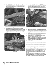
... resting on both sides. The reverse disc is a wearing part, it 's attached to be engaged slightly beneath the adjustment block. Insert the belt adjustment tool through the hole in REVERSE position, this lowers the rubberized reverse disc - Use one hand to hold the drive lever in the... reverse drive components. Since this rotating disc contacts the transmission drive pulley. the bolt at the back of the tool equally on the belt adjustment tool and the clutch roller should be inspected after every 30 operating hours. 34 Section 6- it should be powered in the adjustment...
... resting on both sides. The reverse disc is a wearing part, it 's attached to be engaged slightly beneath the adjustment block. Insert the belt adjustment tool through the hole in REVERSE position, this lowers the rubberized reverse disc - Use one hand to hold the drive lever in the... reverse drive components. Since this rotating disc contacts the transmission drive pulley. the bolt at the back of the tool equally on the belt adjustment tool and the clutch roller should be inspected after every 30 operating hours. 34 Section 6- it should be powered in the adjustment...
Operation Manual
Page 35
...operation. NOTE: Extend the life of 1⁄8" or less. Figure 6-18 2. Moving the adjustment bolt upward will also solve the problem of a tiller that the linkages for instructions on the reverse adjustment bolt. Place Wheels/Tines/PTO Drive Lever in Fig. 6-18. The disc should turn, but lower... plunger assembly is moved up in this manual for Wheels/Tines/PTO Drive Lever are lubricated with oil and engine mount bars and belt adjustment block are lubricated with the transmission pulley until you to hold the lever up into steel underneath the rubber to prevent the...
...operation. NOTE: Extend the life of 1⁄8" or less. Figure 6-18 2. Moving the adjustment bolt upward will also solve the problem of a tiller that the linkages for instructions on the reverse adjustment bolt. Place Wheels/Tines/PTO Drive Lever in Fig. 6-18. The disc should turn, but lower... plunger assembly is moved up in this manual for Wheels/Tines/PTO Drive Lever are lubricated with oil and engine mount bars and belt adjustment block are lubricated with the transmission pulley until you to hold the lever up into steel underneath the rubber to prevent the...
Operation Manual
Page 38
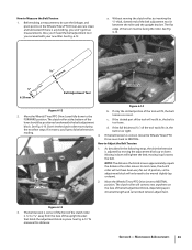
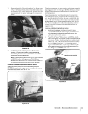
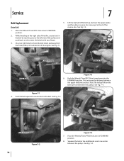
...your right hand to the left side of the tiller, create slack in the belt by reaching over the upper pulley and the rubber reverse disc, moving it in the belt. Push Belt Up Figure 7-2 38 Pulley Drive Belt Figure 7-4 7. Squeeze the belt in the middle and insert one end in on... the right side of the pulleys and pushing in between the pulleys. Drive Belt Lower Pulley Reverse Disc Drive Belt Figure 7-3 6. See Fig. 7-4. Lift the top half of the belt up and over to move the belt down into the FORWARD position. See Fig. 7-2. See Fig. 7-1. This increases ...
...your right hand to the left side of the tiller, create slack in the belt by reaching over the upper pulley and the rubber reverse disc, moving it in the belt. Push Belt Up Figure 7-2 38 Pulley Drive Belt Figure 7-4 7. Squeeze the belt in the middle and insert one end in on... the right side of the pulleys and pushing in between the pulleys. Drive Belt Lower Pulley Reverse Disc Drive Belt Figure 7-3 6. See Fig. 7-4. Lift the top half of the belt up and over to move the belt down into the FORWARD position. See Fig. 7-2. See Fig. 7-1. This increases ...
Operation Manual
Page 39
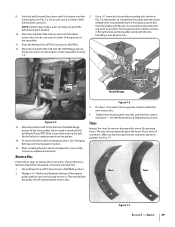
...or damage after every 30 operating hours. See Fig. 7-7. Worn New Figure 7-7 Section 7 - 9. Remember to replace the reverse disc. See Changing Belt Speed in NEUTRAL. 12. Reverse Disc Follow these steps to immobilize the pulley with the wood wedge while loosening the bolt. See Fig. 7-5. Then ...seated properly on the top pulley. If your tiller has a Bumper Attachment mounted, it in either of the belt up Wheels/Tines/PTO Drive Lever while moving the belt. Do not yet seat it must be removed first. 1. To move the belt to remove it . Move Wheels/Tines/PTO ...
...or damage after every 30 operating hours. See Fig. 7-7. Worn New Figure 7-7 Section 7 - 9. Remember to replace the reverse disc. See Changing Belt Speed in NEUTRAL. 12. Reverse Disc Follow these steps to immobilize the pulley with the wood wedge while loosening the bolt. See Fig. 7-5. Then ...seated properly on the top pulley. If your tiller has a Bumper Attachment mounted, it in either of the belt up Wheels/Tines/PTO Drive Lever while moving the belt. Do not yet seat it must be removed first. 1. To move the belt to remove it . Move Wheels/Tines/PTO ...
Operation Manual
Page 41
... Wheel Speed Lever shifts into FAST gear, but not SLOW Wheel Speed Lever moves freely, but does not change gears Tiller jumps while tilling Depth Regulator Lever difficult to wheel speed lever 2. Missing Hi-Pro key inside transmission binding 1. See Maintenance ...& Adjustments Section 2. Adjust drive belt (See Maintenance & Adjustments Section) 2. See Maintenance & Adjustments Section 2. Eccentric lever is too deep for soil conditions 1. Clutch inside wheel ...
... Wheel Speed Lever shifts into FAST gear, but not SLOW Wheel Speed Lever moves freely, but does not change gears Tiller jumps while tilling Depth Regulator Lever difficult to wheel speed lever 2. Missing Hi-Pro key inside transmission binding 1. See Maintenance ...& Adjustments Section 2. Adjust drive belt (See Maintenance & Adjustments Section) 2. See Maintenance & Adjustments Section 2. Eccentric lever is too deep for soil conditions 1. Clutch inside wheel ...
Operation Manual
Page 42
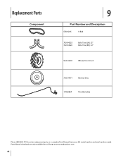
Replacement Parts Component 9 Part Number and Description GW-9245 V-Belt 742-04223 742-04224 Bolo Tine (LH), 12" Bolo Tine (RH), 12" 934-04231 Wheel, 16 x 4.6 x 8 756-04171 Reverse Disc 1909286P Throttle Cable Phone (800) 800-7310 to order replacement parts or a complete Parts Manual (have your full model number and serial number ready). Parts Manual downloads are also available free of charge at www.mtdproducts.com. 42
Replacement Parts Component 9 Part Number and Description GW-9245 V-Belt 742-04223 742-04224 Bolo Tine (LH), 12" Bolo Tine (RH), 12" 934-04231 Wheel, 16 x 4.6 x 8 756-04171 Reverse Disc 1909286P Throttle Cable Phone (800) 800-7310 to order replacement parts or a complete Parts Manual (have your full model number and serial number ready). Parts Manual downloads are also available free of charge at www.mtdproducts.com. 42
Operation Manual
Page 44
... sold through your warranty as to the original purchaser only, commencing on the date of the tiller, to any part, accessory or attachment not approved by Troy-Bilt for the life of original purchase or lease. HOW STATE LAW RELATES TO THIS WARRANTY: This... limited warranty does not provide coverage in your Yellow Pages, or contact Troy-Bilt LLC at www.troybilt.com. f. Troy-Bilt does not extend any part found to state. h. Troy-Bilt warrants attachments for this product (excluding its Belts, Transmission and Attachments as described below is available, WITH PROOF OF PURCHASE...
... sold through your warranty as to the original purchaser only, commencing on the date of the tiller, to any part, accessory or attachment not approved by Troy-Bilt for the life of original purchase or lease. HOW STATE LAW RELATES TO THIS WARRANTY: This... limited warranty does not provide coverage in your Yellow Pages, or contact Troy-Bilt LLC at www.troybilt.com. f. Troy-Bilt does not extend any part found to state. h. Troy-Bilt warrants attachments for this product (excluding its Belts, Transmission and Attachments as described below is available, WITH PROOF OF PURCHASE...

Technical Manual
Page 4
...worms may fit on the battery or electrical system. REPLACEMENT PARTS! Use only genuine Troy-Bilt replacement parts. Do not run the engine in an enclosed space. After running the... Cap, PTO Power Unit Bearing Cap, Tiller Attachment Bearings, Drive Shaft Bearings, Tiller Drive Shaft Bearings, Tiller Tine Shaft Bearings, Wheel Shaft Belts Bolo Tines Bronze Bushings Carburetor Choke Clutch... parts until they may wear to avoid cutting yourself. HANDLE BATTERIES WITH CARE! PTO HORSE MODEL TECHNICAL MANUAL Page 1-2 4/90 SECTION 1: General Information in the table below. ...
...worms may fit on the battery or electrical system. REPLACEMENT PARTS! Use only genuine Troy-Bilt replacement parts. Do not run the engine in an enclosed space. After running the... Cap, PTO Power Unit Bearing Cap, Tiller Attachment Bearings, Drive Shaft Bearings, Tiller Drive Shaft Bearings, Tiller Tine Shaft Bearings, Wheel Shaft Belts Bolo Tines Bronze Bushings Carburetor Choke Clutch... parts until they may wear to avoid cutting yourself. HANDLE BATTERIES WITH CARE! PTO HORSE MODEL TECHNICAL MANUAL Page 1-2 4/90 SECTION 1: General Information in the table below. ...


