Operation Manual
Page 17
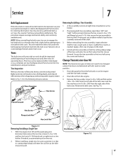
...the bail and hold it so that the drive belt is empty. 2. Badly worn tines will become shorter, narrower and pointed. Rear/Operator Removing/Installing a Tine Assembly: 1. If necessary, use , the tines will result in a loss of tilling depth, and reduced effectiveness when chopping up and ... fuel tank is tight before removal. See Fig. 7-2. Tines The bolo tines will enter the soil first when the tiller moves forward. The procedure requires average mechanical ability and commonly available tools. A tine assembly consists of the tines will wear with dirt, sand or metal particles. 1. ...
...the bail and hold it so that the drive belt is empty. 2. Badly worn tines will become shorter, narrower and pointed. Rear/Operator Removing/Installing a Tine Assembly: 1. If necessary, use , the tines will result in a loss of tilling depth, and reduced effectiveness when chopping up and ... fuel tank is tight before removal. See Fig. 7-2. Tines The bolo tines will enter the soil first when the tiller moves forward. The procedure requires average mechanical ability and commonly available tools. A tine assembly consists of the tines will wear with dirt, sand or metal particles. 1. ...
Service Manual
Page 5
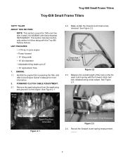
... _____. 1 FORWARD CLUTCH CABLE ADJUSTMENT: 2.1. ward clutch spring with the Troy-Bilt Factory School. See Figure 2.1. Make certain the forward clutch bail is powering the tiller, and refer to follow along with the forward clutch bail fully released using...14" tilling width • 10" tine diameter • Adjustable tilling depth up to the engine. ENGINE: 1.1. Fully Released Figure 2.3 2.4. Troy-Bilt Small Frame Tillers Troy-Bilt Small Frame Tillers TUFFY TILLER ABOUT THIS SECTION: NOTE: This section covers the Tuffy rear tine tiller, model 21A-630B063 with Serial Number ...
... _____. 1 FORWARD CLUTCH CABLE ADJUSTMENT: 2.1. ward clutch spring with the Troy-Bilt Factory School. See Figure 2.1. Make certain the forward clutch bail is powering the tiller, and refer to follow along with the forward clutch bail fully released using...14" tilling width • 10" tine diameter • Adjustable tilling depth up to the engine. ENGINE: 1.1. Fully Released Figure 2.3 2.4. Troy-Bilt Small Frame Tillers Troy-Bilt Small Frame Tillers TUFFY TILLER ABOUT THIS SECTION: NOTE: This section covers the Tuffy rear tine tiller, model 21A-630B063 with Serial Number ...
Service Manual
Page 15
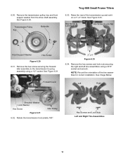
... shaft assembly. See Figure 6.30. Transmission Pulley Key Belleville Troy-Bilt Small Frame Tillers 6.33. Remove the hex screw securing the forward idler assembly to the transmission housing assembly using a 9/16" socket and wrench. Rotate the transmission horizontally 180°. Raise the rear of the tine assemblies for correct installation. See Figure 6.31. NOTE: Record...
... shaft assembly. See Figure 6.30. Transmission Pulley Key Belleville Troy-Bilt Small Frame Tillers 6.33. Remove the hex screw securing the forward idler assembly to the transmission housing assembly using a 9/16" socket and wrench. Rotate the transmission horizontally 180°. Raise the rear of the tine assemblies for correct installation. See Figure 6.31. NOTE: Record...
Service Manual
Page 17
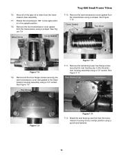
.... Remove the front transmission cover gasket from the transmission case assembly. 7.7. See Figure 7.8. Wheel Worm Cover Gasket Troy-Bilt Small Frame Tillers 7.10. Remove all of the gear oil to the transmission housing assembly using a punch and hammer. 13 See...screw securing the rear bearing cap to drain from the transmission using a 1/2" socket. Break the rear bearing cap free from the transmission using a scraper. 7.6. See Figure 7.11. Cover Gasket Tine Worm Figure 7.8 7.9. Rear Bearing Cap Transmission Overlap Point Rear Transmission Cover Figure ...
.... Remove the front transmission cover gasket from the transmission case assembly. 7.7. See Figure 7.8. Wheel Worm Cover Gasket Troy-Bilt Small Frame Tillers 7.10. Remove all of the gear oil to the transmission housing assembly using a punch and hammer. 13 See...screw securing the rear bearing cap to drain from the transmission using a 1/2" socket. Break the rear bearing cap free from the transmission using a scraper. 7.6. See Figure 7.11. Cover Gasket Tine Worm Figure 7.8 7.9. Rear Bearing Cap Transmission Overlap Point Rear Transmission Cover Figure ...
Service Manual
Page 35
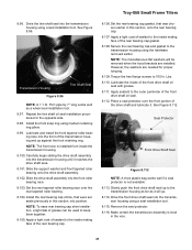
...needed for the opposite side. 8.98. Place a seal protector over the rear tapered roller bearing. 8.104. Troy-Bilt Small Frame Tillers 8.96. Set the rear bearing cap gasket, that were set aside previously in this section, onto the rear bearing cap. 8.107. Seal Protector Front Drive Shaft Seal Figure 8.112 ... sealant to the transmission housing as far as a wheel seal installation tool. 8.97. Repeat the tine shaft oil seal installation procedures for proper torquing. 8.109. Install the rear bearing cap shims, that was chosen earlier in the vice. 31 Apply sealant to 100 In. ...
...needed for the opposite side. 8.98. Place a seal protector over the rear tapered roller bearing. 8.104. Troy-Bilt Small Frame Tillers 8.96. Set the rear bearing cap gasket, that were set aside previously in this section, onto the rear bearing cap. 8.107. Seal Protector Front Drive Shaft Seal Figure 8.112 ... sealant to the transmission housing as far as a wheel seal installation tool. 8.97. Repeat the tine shaft oil seal installation procedures for proper torquing. 8.109. Install the rear bearing cap shims, that was chosen earlier in the vice. 31 Apply sealant to 100 In. ...


